
Abstract
In this paper, we aim to realize compliant biped walking on uneven terrain with point feet. A control system is designed for a 5-link planar biped walker. According to the role that each leg plays, the control system is decomposed into two parts: the swing leg control and the support leg control. The trajectory of the swing foot is generated in real-time to regulate the walking speed. By considering the reaction torque of the swing leg's hip joint as disturbance, a sliding model controller is implemented at the support leg's hip joint to control the torso's posture angle. In order to make sure the landing foot does not rebound after impact, the vertical contact force control is set as the internal loop of the hip's height control. In simulation, the control system is tested on a virtual 5-link planar biped walker in Matlab. Finally, stable biped walking is realized on uneven terrain with roughness up to 2cm.
1. Introduction
Until now, biped walking on flat ground has been well studied. In order to improve the practicability of a biped robot, the walker should be able to walk on uneven terrain. Since the profile of uneven ground cannot be known in advance, unexpected collisions may happen continually during walking. Every unexpected collision may cause a large reaction force to the landing foot and, as a result, the robot may rebound and fall down. One candidate solution to this issue is not only to change the desired trajectory of the landing foot in real-time, but also to control the contact force actively.
For the biped walker with flat feet, the ZMP (zero moment point) criterion [1] is widely used in walking pattern generation [2–5]. According to the ZMP criterion, the centre of pressure should be kept within the support polygon to perform dynamic stabilization [1]. However, for biped walking, it is not necessary to satisfy the ZMP criterion during the whole of the walking [6]. When the walker suffers an unstable situation, as a human does, it can take certain steps to avoid falling down. With flat feet, the biped walker is able to stand stably. Usually, when considering walking ability, flat feet are ignored to simplify the analysis [7–10].
With point feet, the ZMP criterion cannot be used in walking pattern generation. With the assumption that the coefficient of friction equals 1, Cenk Oguz Saglam and Katie Byl controlled the swing leg to pose two different constant configurations during the single support phase [10]. J. G. Ketelaar et al. retracted the swing leg in the first half of the single support phase and extended it in the second half [11]. Wight et al. swung the swing leg forward, such that the angle between the support foot and the swing foot, with respect to the centre of mass (COM), reached the desired value [12]. The desired angle was calculated according to the foot placement estimator (FPE), by solving the FPE equation numerically [13]. Twan Koolen integrated an appropriately chosen desired acceleration in order to obtain the desired velocity and position of the swing foot during each single support phase [14]. However, these methods of walking pattern generation have ignored walking speed control.
In order to realize compliant walking, the contact force between the support foot and the ground should be controlled actively. Usually, impedance control is used for active compliant control in a biped robot [2, 3, 15]. However, this control method needs the ZMP criterion to be satisfied during walking. Thus, the walking speed is very slow. N. Wu et al. designed a point-contact type foot with hydraulic fluid balance mechanism for biped walking on uneven terrain [16]. M. Ogino et al. changed the walking modes depending on the walker's walking speed on uneven terrain [17], which effectively improved the biped robot's walking capability.
In this paper, we aim to realize biped walking on uneven terrain with point feet, and restrict our attention to the planar motion. In section 2, the dynamics of a biped walker are presented. In section 3, a control system is designed for the biped walker according to the role that each leg plays. The control system comprises two parts: swing leg control and support leg control. The trajectory of the swing foot is generated in real-time to regulate the walking speed. For support leg control, sliding model controllers are used to control the torso's posture angle and the hip's height with controlled contact force. In section 4, we implement a simulation to test the control system. Section 5 concludes the paper and provides the direction for future work.
2. Dynamics
A 5-link planar biped walker, as depicted in Figure 1, comprises a torso and two symmetric legs with point feet. Biped walking, as is well known, is realized by consecutive alternation between a single support phase and double support phase. During the single support phase, a set of generalized coordinates can be selected as

A 5-link planar biped walker: (a) physical parameters; (b) generalized coordinates
The dynamics of the walker during the single support phase are [18–20]:

where
When the swing foot gets in contact with the ground, the walker enters the double support phase. Many researchers assume the double support phase to be instantaneous, and model the interaction between the swing foot and the ground as an inelastic rigid impact [7, 10, 21, 22], such that the swing foot will not rebound or slip after impact. However, the contact constraint cannot be preserved without proper contact force control in practice.
By modelling the legs as massless springs, some researchers have studied the control problem during the double support phase [23, 24]. However, in common with human-like walking, the duration of the double support phase is obviously very short.
In this paper, we assume that one of the legs is playing the role of the support leg, while the other is playing the role of the swing leg at any given time, even when both legs are in contact with the ground. Once the swing leg makes contact with the ground, the roles of the two legs will be exchanged. As a result, the states of the generalized coordinates should be updated. Here, the interaction between the foot and ground is modelled as a nonlinear spring-damp model, i.e.:

where μ is the coefficient of friction. Further details for this contact model are explained in [25, 26].
After the roles of the two legs exchange, the new swing leg should be uplifted quickly. Consequently, the contact force will reach zero quickly, and the influence to the dynamics of the walker can be ignored. Then, the complete dynamics for biped walking can be expressed as:

where Q represents a family of switching surfaces on which the roles of the two legs are exchanged.
3. Walking Control
For biped walking, there are three significant control tasks: the walking speed, the torso's posture angle
3.1. Control architecture
Generally, the walking speed is specified by the COM's horizontal velocity. Due to the inevitable parameter estimation errors, especially the distribution of mass, it is difficult to calculate the position of COM precisely, considering the COM is usually close to the hip, in this paper, we treat the hip as the walker's COM.
In light of the point foot, the dynamics during the single support phase are underactuated and the hip's horizontal velocity cannot be controlled to be a constant. The only way to regulate the walking speed, i.e., the hip's average horizontal velocity in a single support phase, is landing the swing foot towards a proper placement. Usually, the landing placement is given by the touchdown angle, which is measured in reference to the hip [27–29]; as such, the swing leg control can be implemented in the local frame attached to the torso.
When considering the reaction torque and forces of the swing hip joint as disturbance, the dynamics of the torso's posture angle and the hip's height mainly depend on the torques of the support knee and hip joints. The biped walking control can then be decomposed into two parts: a) the swing leg control, which includes uplifting and moving the swing foot forward, then landing at a proper placement to begin a new step; and b) the support leg control, which includes preserving the stability of the torso's posture and the hip's height.
In this paper, we treat the swing leg control as a trajectory-tracking control in the task space of a 2-link fixed base manipulator. Since the control problem is well studied, the main problem here is the online trajectory generation for biped walking.
When walking on uneven terrain, active contact force control should be realized to reduce the impact force and preserve the contact constraint. Using the foot-ground contact model, as shown in (2), the vertical contact force can be calculated. In practice, the vertical contact force can be measured by a force sensor. With the feedback contact force, we will design an active compliant controller later. The complete control architecture for biped walking is shown in Figure 2.
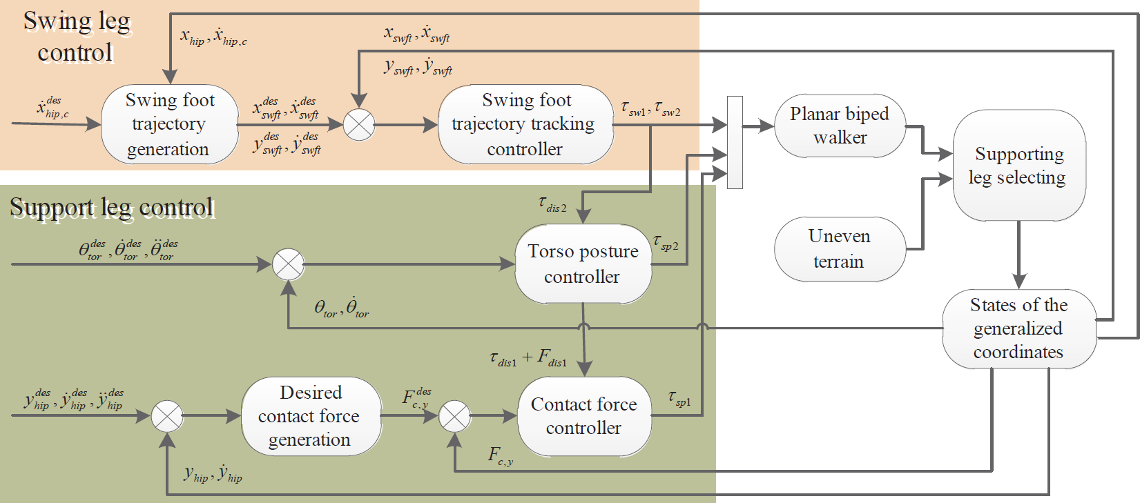
Architecture for biped walking control
3.2. Swing foot trajectory generation
Generally, the hip's average velocity is in direct proportion to the hip's velocity at the moment that the swing foot is exactly above the support foot. In this paper, we call this the middle support moment (MSM). The trajectories of the swing foot before and after the MSM will be planned separately.
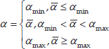
A variation of Raibert's speed controller is employed to regulate the hip's horizontal velocity at the MSM [28, 29]:

where αn is the nominal touchdown angle,

For the most part, it is desirable that the swing foot lands in front of the support foot and, in order to make sure the new support foot does not slip at the beginning of a new single support phase, the touchdown angle is designed as:
where
The desired landing placement is:

A typical single support phase contains three crucial moments, as shown in Figure 3.

Three crucial moments of a single support phase
The solid lines denote the support leg and torso, while the dashed lines denote the swing leg. The dash-dotted lines denote the desired trajectory of the swing foot. The trajectory can be planned as a function of time [20, 30] or the geometric evolution of the biped walker [27, 31]. Since the duration of every single support phase is difficult to estimate when walking on uneven terrain, the latter option is adopted in this paper. During walking, the horizontal location of the hip with respect to the support foot increases monotonically, consequently, it can be selected as the parameter for the desired trajectory.
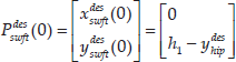
As shown in Figure 3, the constraint equations for the swing foot's desired trajectory are described as follows:
The moment that a single support phase is beginning:


where
The MSM:

The moment when the hip arrives at Xn:


Using three order polynomial functions of
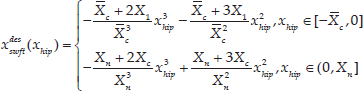
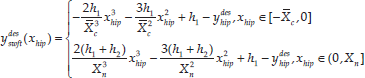
where h1 is the maximum clearance of the swing foot. In order to make sure the swing foot is able to come into contact with ground, h2 is set to be slightly larger than the absolute roughness of the ground. Note that, because the ground is uneven and it cannot be accurately predicted where the swing foot will land,
3.3. The torso's posture control
When considering the reaction torque of the swing hip joint as disturbance, the rotational dynamics of the torso can be expressed as:

where
Usually, it is desirable to keep the torso upright during walking; that is:

Let

The derivative can be derived as:

A sliding mode controller can be designed as [32]:

where

Since the magnitude of the reaction torque of the swing hip joint is finite, there will always be a positive
3.4. The hip's height control
Generally, during biped walking, the hip's vertical oscillation should be kept to a minimum. In this paper, the desired height of the hip is set as:

Note that the hip's height is measured with respect to the support foot, since the hip's height mainly depends on the distance between the support point and the hip, which is equivalent to the angle of the support knee joint. In this paper, we use the support knee joint to control the hip's height.
The desired vertical contact force is calculated as:

where

where τ0 is calculated from the forth equation of (1) by neglecting the dynamic states,
Note that the hip's height controller comprised by (23) and (24) is essentially different from the impedance controller as in [3, 15]. Since impedance control aims to track the desired contact force, the desired position is regulated according to the contact force error. Consequently, the impedance control is usually used in a walker with flat feet, and the ZMP criterion is used to calculate the desired contact force. Here, the hip's height control is the external loop, while the contact force control is the internal loop. Therefore, not only can the precision of the hip's height be preserved, but the contact force will also not be too large due to restricting the magnitude of the desired value.
4. Simulation
We built a 3D biped walker by SolidWorks 2012, as shown in Figure 4(a). The physical parameters of the 3D biped walker are shown in Table 1. To validate the designed control system, we built a virtual 5-link planar biped walker with the Matlab SimMechanics toolbox, using the parameters in Table 1, as shown in Fig. 4(b). The uneven ground profile is defined as:

3D biped walker and 2D simulation model
Physical parameters of the biped walker


With the initial configuration in Table 2, the walker's COM is located at the right side of the support foot. Consequently, the walker will fall forward under the action of gravity. Due to the limitation in computer memory, the simulation time is set to last 20 seconds. During these 20 seconds, the planar biped walker takes 52 steps successfully.
Initial states of the robot. Set the right leg as the support leg initially

Figure 5 shows the phase plane limit cycle of the hip's horizontal motion. The initial state and the final one are specified by a star and circle, respectively. In simulation, the desired hip velocity at the MSM is set to
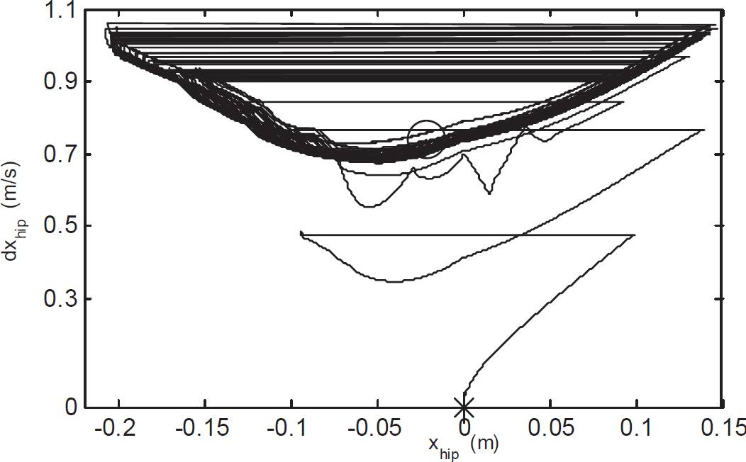
Phase plane limit cycle of the hip's horizontal motion
Figure 6 shows the torso's posture angle. It can be found that the torso's posture angle evolves rapidly at the beginning of every single support phase due to impact. However, the oscillation of the torso's posture angle is less than 0.003rad in the end, which is acceptable for a walking motion. The largest oscillation with an absolute value of 0.012rad comes from the second step.

The torso's posture angle
Figure 7 shows the hip's height with respect to the support foot. Since the oscillation of the ground profile is 0.02m, the hip's height may be 0.02m larger or smaller than the desired value at the beginning of a single support phase. With the designed controller, the hip's height is able to converge to the desired value quickly in each single support phase.

Hip height
For clearance purposes, Figures 8, 9 and 10 only show parts of the simulation results. Figure 8 shows the vertical contact force control result. In order to make sure the support foot does not rebound, the desired vertical contact force is restricted within the range of 250N to 1500N. Through the entire simulation, the vertical contact force is less than 2000N. Once the hip's height controller is replaced by a pure position controller, the vertical contact force will be much too large, which results in a rebound of the landing foot and a failure in walking.
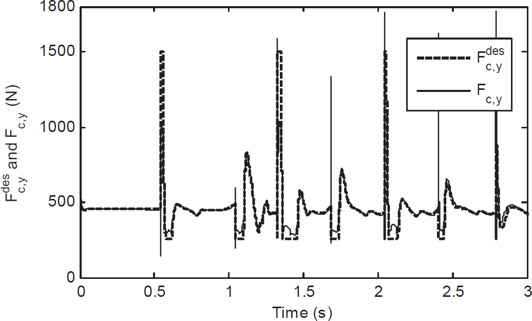
Vertical contact force control result

Horizontal contact force in a typical single support phase

Trajectories of the swing foot
Figure 9 shows the horizontal contact force in a typical single support phase. The dashed line specifies the bound of friction force, which is calculated by multiplying the vertical contact force with the coefficient of friction. It can be found that the horizontal contact force is within the friction cone, except for the beginning and the end of the single support phase. This is because the contact model is a spring-damp model, as a result, the flexibility distortions in the horizontal and the vertical direction reveal a pseudo-slipping phenomenon at both the beginning and the end of the contact process.
Figure 10 shows the trajectories of the swing foot with respect to the hip joint. Due to the uneven ground profile, the desired position of the swing foot at the beginning and end of every single support phase will be different. In order to preserve the continuity of the desired trajectories, the desired position of the swing foot at the beginning of every step is set to be the current position. In simulation, the well-known PD-type controller for a 2-link fixed base manipulator is implemented for the swing foot task space trajectory tracking control.
Considering the practical restriction of an actuator, the actuation torque of each joint is restricted in the range of −150 to 150 in simulation, as shown in Figure 11.

Actuation torque of each joint of the right leg during walking
5. Conclusions
In this paper, we aim to realize compliant biped walking on uneven terrain. According to the role that each leg plays, the control system of the biped walker comprises two parts: the swing leg control and the support leg control. The trajectory of the swing foot is generated in real-time to regulate the walking speed. By considering the reaction torque of the swing leg's hip joint as disturbance, a sliding model controller is implemented in the support leg's hip joint to control the torso's posture angle. In order to make sure the swing foot does not rebound after impact, the vertical contact force control is set as the internal loop of the hip's height control. To validate the designed control system, simulation is implemented on a virtual 5-link planar biped walker in Matlab. The physical parameters of the walker come from a 3D biped walker built by SolidWorks 2012. In simulation, stable biped walking is realized on uneven terrain with roughness of up to 2cm.
Future work will be pursued in two directions: 1) extending the control system into a virtual 3D biped walker, and 2) constructing a real biped walker to test the control system.
Footnotes
6. Acknowledgements
This work was supported by the Crossing Specialties Co-educating Program for PhD students in the National University of Defense Technology (no. kxk140101), the National High Technology Research and Development Program of China (no. 2011AA040801) and the National Natural Science Foundation of China (no. 61473304)