
Abstract
Humanoid robots are expected to achieve stable walking on uneven terrains. In this paper, a control algorithm for humanoid robots walking on previously unknown terrains with terrain estimation is proposed, which requires only minimum modification to the original walking gait. The swing foot trajectory is redesigned to ensure that the foot lands at the desired horizontal positions under various terrain height. A compliant terrain adaptation method is applied to the landing foot to achieve a firm contact with the ground. Then a terrain estimation method that takes into account the deformations of the linkages is applied, providing the target for the following correction and adjustment. The algorithm was validated through walking experiments on uneven terrains with the full-size humanoid robot Kong.
1. Introduction
Achieving movements in human environments is one of the most important goals in humanoid robot research. However, walking on uneven terrains, especially on previously unknown terrains, is highly challenging. Therefore related works are relatively less fruitful while abundant researches have been made on walking speed and other aspects for walking on even terrains. The DAPAR Robotics Challenge (DRC) for disaster response scenarios showed that the capability to traverse different types of terrains is crucial for robots to assist humans in harsh environments [1], and yet such capability is still quite limited. The capability of adapting to uneven terrains is then raised as a key factor in the development of practical robots. Although vision and laser sensors can be assists for robots to perceive the environments, the problems of inaccuracy, hardware and computational cost limit the effectiveness. Hence, it is still necessary to study biped walking on uneven terrains without complete and reliable information of the environment.
Previous works on biped walking on uneven terrain can be divided into two major categories according to their different control methods: the dynamics-based methods and the model-based methods [2]. The dynamics-based methods, includes the passive walking [3], the Central Pattern Generator (CPG) method [4], the Virtual Model Control (VMC) method [5], etc. These methods achieve walking on uneven terrains through the robustness of their systems. And in some studies the model of the terrain was already given [6]. The stability analyses of these methods are complex, and usually rely on precise dynamics models of both the robots themselves and their impacts with the ground. Therefore, the implementation results of these methods can be considerably uncertain.
The majority of the model-based methods are variants of the Zero Momentum Point (ZMP) method. These methods achieve walking on uneven terrains by gait adjustments, or by using specially designed foot mechanisms [7, 8], which will not be discussed here in consideration of universality. The former can be further classified by whether modeling the uneven terrains with available sensor information or not. The methods without modeling the terrain focus on the negative effects caused by the non-ideality of the terrains. Hence they actually handle the uneven terrains along with all other non-ideality factors. Walking is stabilized by body acceleration [9, 10, 11], body rotation [12], or foot landing point adjustment in these methods [13, 14, 15]. On the contrary, the methods involving terrain modeling can make adjustments according to the conditions of the uneven terrains. Besides those methods obtaining terrain information from vision [16] or laser [10, 17, 18] as mentioned above, previous researches usually acquired terrain information from both the force-torque information during the foot landing period and the attitude information during the following single support phase [19, 20]. Accordingly, walking was stabilized by both instant adjustments in supporting foot posture and later adjustments in gait such as landing time. A “global terrain” was usually introduced in these works which assumed that there is a general trend in the variation of the terrain. This assumption actually reduced the difficulty of terrain modeling since previous terrain information can be used to reduce the uncertainty of terrain at current landing point. Impedance control is widely applied to achieve compliant foot landing in all these model-based methods.
The methods without terrain modeling lower the complexity of the control systems. However, as these methods are not specific to the conditions of the terrains, the potential to maintain the original gaits is actually lost. Meanwhile, variable walking parameters like step length and walking cycle period are modified, which might leave less margin for resisting other disturbances. On the contrary, the methods involving terrain modeling require less change to the trajectories of the Center of Mass (COM) and save the variable parameters for both faster walking and resisting disturbances. However, acquiring the terrain information is not easy yet, especially when demanded to be accomplished right after the landing of the foot. Some researchers thought it is difficult or even impossible to model the terrain accurately with only the information gathered during the short landing period [19].
We found that there are two major difficulties in building an online terrain model. First, rapid adaptation to the uneven terrain without hard impact is a challenge. Second, the elastic deformations of the legs that reduce the reliability of the kinematics should be taken into consideration. Hence, a new adaptation method based on the classic impedance control is proposed, which eliminates the coupling between the roll/pitch rotation and the vertical displacement by the feedforward strategy. This method prevents the repeated impact between the landing foot and the terrain, and also shortens the adaptation period. Meanwhile, a new terrain estimation method is designed, which calculates the decline of the landing foot through the rotation about the Center of Pressure (COP) rather than the normal forward kinematics using just the joint angles. The terrain estimation is accurate enough that only the height of the COM needs to be adjusted, so the original offline gait generated by the previewed control method [21] is highly preserved. The swing foot trajectory is also redesigned to cope with the uncertainty of the terrain.
The remainder of the paper is organized as follows. Section 2 gives an overview of all the proposed methods and a framework of the control system. Section 3 describes a redesigned swing foot trajectory. Section 4 introduces the terrain adaptation method in detail. In section 5, the terrain estimation method is described, along with the corresponding correction and adjustment strategies. In section 6, the experimental results are given and discussed. Finally, section 7 concludes the paper.
2. Overview of Methods
In this section, the assumptions of the problem and the framework of the control system are given.
2.1. Assumptions
In this paper, the robot is desired to walk on uneven terrains in the same manner as it does on even floor. There are many kinds of uneven surface conditions for robots. The following assumptions are made to restrict and simplify the problem:
The trend of the terrain is stochastic.
The height range of the terrain within the projection of the landing foot, represented by
The support region is big enough to provide enough ZMP margin after the landing foot made a firm contact with the ground.
The stiffness of the terrain is consistent and is hard enough to avoid visible deformations.

Scheme of the uneven terrain
2.2. Framework of control system
A state machine for the control system is designed, as shown in Figure 2. Comparing to the traditional state machine for biped walking, there are two differences:
Touching phase is introduced for the adaptation process of the landing foot.
The states for the left and the right foot are separated without the double support phase connecting them, as it is possible that one foot enters the flight phase when the other hasn't finished the touching phase.

State machine of the control system
The framework of the control system is shown in Figure 3. In this control process, the preview control method is used to generate the offline COM trajectory with the gait parameters, like the step length and the scheduled landing time (which is the deadline for the actual landing). To realize walking on an uneven terrain, the following methods should be applied at different stages:
Redesigned swing foot trajectory. Due to the height variation of the terrain, the landing moment can be earlier or later than expected [22]. To ensure the swing foot touches the ground at desired horizontal position before the scheduled landing time, the swing foot trajectory should be redesigned.
Compliant adaptation of the landing foot to the terrain. The landing foot should actively adapt to the uneven terrain using the force-torque sensor information after it touches the ground.
Correction and adjustment based on terrain estimation. The pose of the landing foot calculated through the forward kinematics is not reliable because of the non-ideality factors such as the deformation of the linkages and the inclination of the body. And the height of the COM should change according to the variation of the terrain. Therefore corresponding corrections and adjustments are needed.
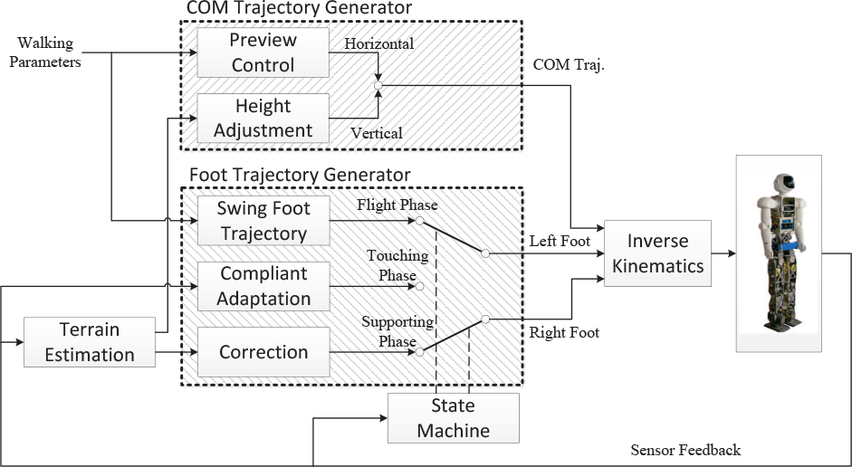
Diagram of the overall control framework
3. Redesigned swing foot trajectory
As mentioned above, the swing foot should have touched the ground at the desired horizontal position before the scheduled landing time, as long as the height of the terrain falls into the allowed range. Therefore the horizontal components of the trajectory should reach the target value before the vertical component does. And the end of the planned trajectory should reach the lower limit of the terrain to guarantee a contact. Additional requirements for the swing foot trajectory are given as follows:
The continuity of the velocity should be guaranteed.
The maximum vertical decline velocity should be limited to avoid hard impacts.
The swing foot should not stay near the ground for too long in order to avoid repeated impacts with the ground.
Components of the trajectory other than the vertical displacement are all set to be sinusoids that reach the target values before the scheduled landing time and then hold the target values, for example, the displacement in the front-rear direction

where

where
We set the vertical displacement component of the trajectory as a piecewise function composed of four parabolas, as shown in Figure 4. The target value z1 should be the minimum terrain height allowed

where
Given the initial value z0, the target value z1, the height of the trajectory

where


where the saturation function
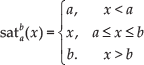
a1, a2, a3, a4, t1 and t2 can be calculated using the smooth condition, which will not be detailed here.

Vertical displacement component of the swing foot trajectory
4. Compliant Adaptation of Landing Foot
Theoretically, the compliance control should be applied to all the six Dimensions of Freedom (DOF) of the landing foot in order to avoid slipping between the sole and the ground. In practice, as the horizontal displacement and the yaw rotation can be ignored during the landing process, the compliance control is only used for the roll, the pitch rotations and the vertical displacement.
4.1. Compliance control of roll and pitch rotations
There are two major considerations in choosing the compliance control method for the landing foot. First, the landing foot is supposed to hold its pose when there is no difference between the measured and the reference torque, which implies that the controller should have zero steady state error. Second, the low-pass filter for force/torque sensor signal has a larger phase delay for high frequency components than that for low frequency components. Hence a controller with low-pass property will help to reinforce the closed-loop stability by suppressing high frequency oscillations. The integral property of the damping controller makes it conform to the two requirements above. Therefore the damping control method is used to achieve compliance in the roll and the pitch rotations in this paper.
Given that the reference torque is set to zero, the angular velocity is calculated as

where D is the given damping coefficient, and
There are two remaining issues to be discussed: 1) how to choose an appropriate damping coefficient D and 2) the terminate condition for the compliance control.
4.1.1. Choosing damping coefficient
Ideally, the adaptation always performs better with a smaller D, which makes the foot more compliant. However, when taking time delay into consideration, the system will become divergent when D is too small. Thus there is a lower limit for D.
Assume that the contact between the sole and the terrain is linear elastic with a spring constant K. And use the notation τ for the overall time delay of the control loop. The closed-loop system can then be model as

Discretize Eq. (9) with sampling time Ts and the assumption
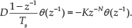
The characteristic equation of Eq. (10) is

Since the characteristic polynomial is continuous about D, and we know that the system can be stable with a big enough D or unstable with a small enough D, there exists a certain

The solution of Eq. (12) is

It can be easily proven that
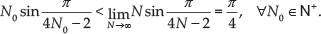

Hence we choose D conservatively with the criterion

The value of τ can be obtained from the mechanism model of the system. The value of K varies under different contact conditions. Obviously when the foot makes a full contact with an even floor, K reaches its maximum value
4.1.2. Stages and terminate conditions
Ideally, the adaptation completes when the measured torque
The damping coefficient D is set to be
D is set to a certain value
4.2. Feedforward and feedback control of vertical motion
The vertical motion is related to the roll and the pitch rotations during the adaptation, as the contact point about which the foot rotates rarely falls at the center of the sole. A feedforward compensation is therefore designed to improve the performance. The overall control law is

where
4.2.1. Feedforward controller
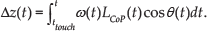
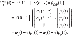
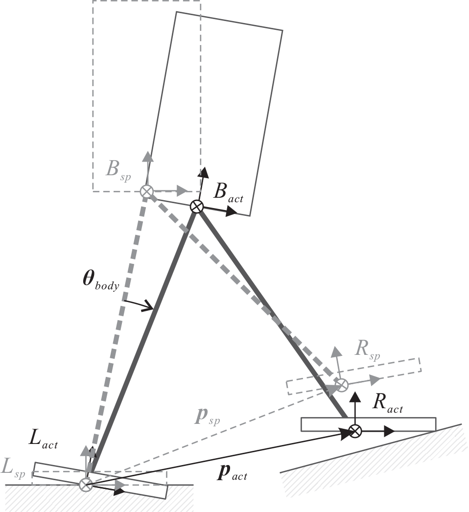
To simplify the discussion, relation between the vertical motion and the rotation along one single axis is studied first, as shown in Figure 5.

Relation between the vertical motion and the rotation of the landing foot
With the sole in continuous contact with the ground, and the derivative of
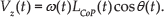
Then the descending distance since the moment
However, time delay should be taken into consideration or Eq. (19) will almost certainly overestimate the descending distance. The measured COP position

The right hand side of Eq. (20) contains information from the future. Approximations are needed to estimate the descending distance online. Since the overall time delay

Similarly, when considering both the roll and the pitch rotations,
where

It will be mentioned in the next section that Eq. (19) also constitutes part of the terrain estimator.
4.2.2. Feedback controller
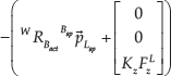
The damping control method is employed in the feedback component of the vertical motion control, just like in the control of the roll and the pitch rotations. The difference is the reference vertical force

where

where
5. Correction and Adjustment
As mentioned above, the pose of the landing foot relative to the body calculated through the forward kinematics is not reliable due to the dynamic deformations in the linkages. Meanwhile the pose of the body in the world coordinates is not desired. Thus if holding the commanded pose of the landing foot at the time
The height of the COM should adjust to the variation of the terrain in order to maintain the vertical distance between the COM and the terrain. This is the only adjustment of the COM trajectory in this research.
5.1. Terrain estimation
The deviation between the calculated and the actual foot pose relative to the body obeys different rules in different phases:
During the supporting phase and the flight phase, including the moment
During the touching phase, the deviation can still be deemed to exist only in the vertical displacement. However it is no longer proportional to the pressure because the deformations of the linkages is dynamic for a period after the impact.
Therefore the height estimation is the key point in the terrain estimation. The basic idea is to use the pose at
Here, we assume the left foot to be the supporting foot and the right foot to be the landing foot. The deviation of the body from its desired pose at
Deviation of the body from its desired pose
The actual position of the right foot in the world coordinates is

where

where


The actual position of the landing foot in the world coordinates at the moment
Method similar to Eq. (19) is used to obtain the descending distance of the landing foot, with additional consideration of the body rotations

With approximations and the time delay, Eq. (29) can be further written as

Thus the position of the landing foot at the moment

where
Besides the position estimation, the attitude of the terrain also needs to be estimated. The rotation matrix of the landing foot in the world coordinates at moment

The terrain estimation is then achieved using Eq. (31) (32).
The vertical spring constant Kz is obtained through identification. Notice that the vertical elasticity comes from both the contact with the ground and the compression of the leg. Hence Kz is smaller than the elastic coefficient calculated from the Young's modulus of the contact materials. Let the robot walk on an even floor with the original open-loop gait. The actual height of the foot at

However, the height calculated through kinematics would be different because of the vertical elasticity. With Eq. (27) and Eq. (33), we have

The mean value of the results from multiple trials is then used as Kz in both the choosing of the vertical damping efficient Dz and the terrain height estimation.
5.2. Correction
With the actual position

To avoid discontinuities in velocities, a same second-order correction process
The damping coefficient ζ is set to 1 as overshoot is undesired. The unit step response of a second-order system under critical damping exceeds 0.9 after the moment

Substitute Eq. (37) into Eq. (36), we have

5.3. Height adjustment
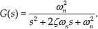
The desired COM height
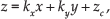
the horizontal motion of this inverted pendulum is the same with that of a linear inverted pendulum. Hence a height adjustment strategy similar to the classic stair climbing algorithm is designed, as shown in Figure 7, with the difference that the terrain height is unknown before the landing of the foot. Once the landing foot has made a firm contact with the terrain and becomes the supporting foot, the robot begins to move its COM within the newly calculated constraint plane, until the COM passes the new supporting foot in the forward direction, after which the COM will move within the horizontal plane as the trend of the terrain in the next step is still unknown.

COM height adjustment according to the terrain
6. Experimental Results
Figure 8 shows the humanoid robot Kong and the uneven terrain used in our experiments. The full-size humanoid robot Kong is 161 cm in height and 53 kg in weight with a total DOF of 14 [24]. A six-dimensional force/torque sensor is mounted in each foot. And an IMU is mounted under the waist between two hips, where the COM is considered to be. The amplifiers communicate with the upper computer through the CAN network. The uneven terrain was built by attaching a 16 mm thick hard plank to a common floor.

The humanoid robot Kong and the uneven terrain used in the experiments
We validated our method by walking experiments with Kong. The walking speed was 0.225 kmph, while the step length was 5 cm. The total step count in each experiment was 12. The first two steps in each experiment didn't use the method proposed in this paper, as to ensure a reliable startup.
Walking experiment on the uneven terrain with the proposed methods was implemented to verify the effectiveness of the methods, as shown in Figure 9. In addition, the walking experiments on an even floor with or without the proposed methods have been compared. The results of walking on the uneven floor without the proposed methods are not shown because the robot fell almost immediately after stepping on the obstacle. The body attitude angles in these experiments are shown in Figure 10 as an indicator of walking stability. The body attitude angles in all these experiments fell within about

Snapshots of the walking experiment on the uneven terrain. Multiple local terrain cases were included.

Body attitude angles of walking on even or uneven terrain with or without the methods proposed in this paper. The start time of the uneven terrain intervention is the moment when the swing foot first touched the uneven terrain. And the end time of the uneven terrain intervention is the moment when the supporting foot left the uneven terrain for the last time.
To examine the effectiveness of the foot compliance, the vertical force Fz on each foot in the experiments with or without the proposed methods are compared, as shown in Figure 11. Only results of walking on the even floor are included in this comparison for the consistency of contact conditions. The contacts started earlier when using the proposed methods because the new swing foot trajectories aimed lower than the traditional trajectories. The vertical force control decreased the first peak in every step significantly, and steadied the vertical force during the adaptations, relieving the “pre-landing” phenomenon. As a result of this impact absorption, Fz during the supporting phase became steadier than that in the result without the new methods. Hence, the foot compliance enhanced the walking stability by reducing the impact, and guaranteed the terrain estimation to be effective by maintaining the landing foot in continuous contact with the ground.

Vertical force on each foot when walking on even floor with or without the proposed methods. Only part of the time axis is shown for the clarity of the figure.
We shall then verify the accuracy of the terrain estimation. As shown in Figure 12, the terrain attitude angle estimation error usually fell within

Estimated and referenced values of the local terrain at each foot landing point. Only part of the time axis is shown for the clarity of the figure. The lines represent the poses of the feet. The markers represent the referenced values of the terrain, whose abscissas correspond the moments when the adjustment finished in each step. Therefore the estimation errors are represented by the vertical distance between the lines and the corresponding markers.
Reference and measured ZMP of walking on even or uneven terrain with the proposed methods are shown in Figure 13. The ZMP following errors are noticeable, as only the offline COM trajectory generated by the basic preview control method was applied, while the robot faced the problems like the modelling error and the oscillation caused by the elasticity of the linkages. Stable walking under such condition shows that the proposed methods are not picky about the high-level controller or the hardware platform. It can also be noted that the measured ZMP of walking on the even and on the uneven terrain differed little except for the time shifting caused by the different landing conditions. Therefore the ZMP trajectory can be expected to be maintained under different terrain conditions.

Reference and measured ZMP of walking on even or uneven terrain with the methods proposed in this paper. The start and end time of the uneven terrain intervention are defined in the same way as in Figure 10.
7. Conclusions and Future Work
In this paper, we propose a control algorithm that enables humanoid robots to walk on uneven terrains. The major difference between our algorithm and previous works is that our algorithm is based on an online terrain estimation, which brings the benefit that only minimum modification to the walking gait is required. The instant terrain estimation is achieved by using information from different sensors at different stages, considering that the forward kinematics is not always reliable because of the deformations in the linkages. In addition, a new swing foot trajectory and a compliant terrain adaptation method for the landing foot are designed to cope with various terrain conditions. We validated our algorithm by walking experiments on the full-size humanoid robot Kong. The results show that the performance of the robot when walking on the uneven terrain is as good as that when walking on the even floor. The effectiveness of the compliant terrain adaptation and the accuracy of the terrain estimation were also verified.
The allowed terrain height variation range
Footnotes
8. Acknowledgements
This research is supported by the National Foundation of China (Grant No. 51405430, Grant No. 61473258 and Grant U1509210).