
Abstract
This paper focuses on planning patterns for biped walking on complex terrains. Two problems are solved: ZMP (zero moment point) cannot be used on uneven terrain, and the conventional cart-table model does not allow vertical CM (centre of mass) motion. For the ZMP definition problem, we propose the extended ZMP (EZMP) concept as an extension of ZMP to uneven terrains. It can be used to judge dynamic balance on universal terrains. We achieve a deeper insight into the connection and difference between ZMP and EZMP by adding different constraints. For the model problem, we extend the cart-table model by using a dynamic constraint instead of constant height constraint, which results in a mathematically symmetric set of three equations. In this way, the vertical motion is enabled and the resultant equations are still linear. Based on the extended ZMP concept and extended cart-table model, a biped pattern generator using triple preview controllers is constructed and implemented simultaneously to three dimensions. Using the proposed pattern generator, the Atlas robot is simulated. The simulation results show the robot can walk stably on rather complex terrains by accurately tracking extended ZMP.
Introduction
It is important to plan walking motion on rough ground for a humanoid or biped robot to perform useful tasks [1]. To plan robot motion, a criterion is required to quantify the walking stability or dynamic balance. As a stability criterion, ZMP has been widely used in motion planning or control of legged robots. ZMP, zero moment point, is a point where the horizontal moments generated by ground reaction forces are zero [2]. Dynamic balance or stability can be judged by checking whether ZMP is within convex hull encompassing the support foot/feet. Although other stability criteria have also been proposed [3–6], ZMP is still the most widely used for its simplicity of form and convenience to measure. It is also problematic in the sense that ZMP is not defined if two feet contact with different planes [7].
To achieve rough ground walking and not make the problem too complex, one issue is of how to define the ZMP on rough ground. The Honda US patent defines the virtual ZMP and virtual surface as linear combination of two local ZMPs and contacting surfaces of both feet, respectively, changing linearly in time from one foot to the other [8]. However, the definition does not conform to the ZMP concept because the resultant moment of gravity and inertial force is not perpendicular to the virtual surface [7].
The virtual slope method was proposed by Sato et al. with virtual ZMP defined on the virtual slope [9]. This method can extend ZMP to uneven terrain. However, the virtual support polygon, which is on the virtual slope, depends on the CM position and it is difficult to determine the exact support polygon in advance.
Under the ZMP criterion, one of the most prevalent ZMP models is the cart-table model proposed by Kajita et al. [10]. The cart-table model assumes the CM motion is constrained on a horizontal plane. This model dramatically reduced the complexity and was widely used in walk planning and control [11–14]. However, the linearity of the cart-table model may not be preserved when vertical motion of CM is allowed, for example, to climb stairs [9]. It can be tackled by assuming a negligible effect of vertical motion on horizontal dynamics [15]. Another way is to compensate the horizontal ZMP error from vertical CM motion by manipulating angular momentum [16]. This paper proposes a model with a dynamics constraint rather than the constraint of constant CM height, and the cart-table model is extended to 3D space. This model does not need angular momentum to compensate for horizontal ZMP error as in [16]. In [17], a new frame was attached to the slope that is parallel to the slope surface to decouple horizontal and vertical motion in planning slope walking. Robot motion is represented in the new frame in a simple form. However, the resulting model depends on the slope gradient. This may need parameter reconfiguration whenever the slope gradient changes. Our model avoids this problem by enabling vertical motion while preserving model linearity.
It is important to change walking pattern in real time for more flexibility. This requires an online motion planning. Ching-Long Shih et al. use the virtual constraint method to generate reference walking trajectories assuming the robot to have pointed feet, and the walking stability is enhanced by a supplemental stabilizing controller [18]. There is also work based on genetic algorithm methods, which make the design of motions more intuitive and versatile [19]. Kajita et al. proposed a preview control-based method taking the pattern planning as a servo tracking problem with ZMP as plant output [10]. The preview control allows the time and location of foot landing to be changed online. This is useful for taking agile motion like emergent stop to avoid collision with obstacles [20]. This feature is therefore important for rough ground walking, as step length and cycle possibly need be modified. Feng et al. used a dynamic programming technique, which also uses future information like preview control, to generate CM motions, and achieved walking on rough terrain [21]. Nishiwaki et al. proposed balancing the robot by changing the reference ZMP of preview control in the permissible region or foot position in the next step for walking on rough terrains [1]. However, it was not related to how to define ZMP on rough ground or how to design vertical motion whilst keeping the robot dynamically balanced. The extended cart-table model and the extended ZMP concept, we propose, will tackle these problems in an elegant style for walking on complex terrains.
This paper mainly focuses on establishing a framework of planning walking on complex terrains. A new criterion-extended ZMP – is proposed as an extension of ZMP to general terrains. Based on some assumptions compatible with ZMP, the extended ZMP concept is explicitly defined and a dynamic equation is derived. We use a novel method based on constraint to analyse EZMP dynamics. It is found that extended ZMP dynamics have the same form as ZMP only under appropriate constraints. Furthermore, the additional constraint can be removed if the angular momentum around CM is neglected. To make the extended ZMP-CM equation linear and enable vertical motion, a dynamic constraint is added to the conventional cart-table model of (E)ZMP equations to form an extended cart-table model. The resulting equation set is composed of three equations in a similar form. To compute CM motion from extended ZMP trajectory, preview control is used in all three directions.
This paper is organized as follows. Section 2 generalizes the classical ZMP concept to universal terrains. Section 3 introduces our proposed model – the extended cart-table model. Section 4 implements triple preview controllers on the extended cart-table model. Section 5 presents the general framework of planning biped walking on rough terrains using preview control, combining the above-mentioned extended ZMP concept and extended cart-table model. Section 6 gives some simulation examples of Atlas robot walking on complex terrains, and the paper is concluded in Section 7 with some discussions on limitations and our future work.
Extending ZMP Concept to Rough Terrains
Extended ZMP Concept
ZMP, or zero moment point, is a point on the horizontal plane where the tipping moment around the horizontal axes is zero [2]. ZMP is on the contact surface and coincides with the CoP (centre of pressure). It is unable to define the ZMP on uneven ground, and a virtual ZMP should be defined instead. To extend the ZMP concept, the following definitions are given:
EZMP is used for rough terrain walking. The next section presents the systematic theoretical framework of EZMP.
Derivation and Analysis of EZMP Based on Constraining
Based on Definition 2, we can derive the EZMP equations in the following.
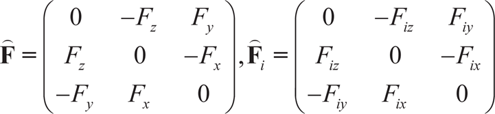
Let n=(nx,ny,nz)T and

This is unfolded as:

Considering

or

where
Let

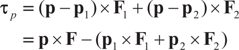
Substitute (5) into (4), and then substitute (4) into (2), we obtain:

where

and

To simplify the dynamics, we add the constraints:

The following can be derived:
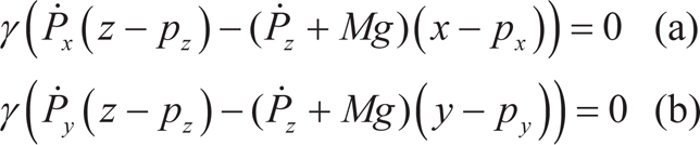
By solving (9a) and (9b), we get:
If γ≠0 means VCP is not vertical, divide (10) and (11) by γ and substitute them into (7c); the simple result is obtained as Cz=0. This makes (9c) a redundant constraint.
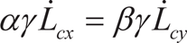
From equation (10), the following is derived:

which is simply the same as classical ZMP dynamics without angular momentum around CM [22]. This means the same EZMP equation (12) as ZMP can be derived by setting constraints (9a) and (9b).
Equation (12) can be arranged as:

and
If we assume a negligible centroidal angular momentum and its derivative, i.e.,
If γ = 0 means VCP is vertical, (9c) cannot be derived from constraints (9a) and (9b). Therefore, constraint (9c) is indispensible. However, by neglecting the centroidal angular momentum, it can also be shown that constraint (9a) (9b) and (9c) are all satisfied by (12) and can be removed (no matter γ≠0 or γ = 0).
We conclude the above as theorems:
In the above two theorems, it is very interesting to notice that the EZMP equations are in the same form while bearing different meanings such as exact and approximate, respectively. This indicates that matching of EZMP dynamics (12) to reality relies on the degree to which the constraint (9) is satisfied. Moreover, if α=β=0, (6) is exactly the ZMP equation based on multibody dynamics. In this sense, EZMP is compatible to ZMP definition.
Until now, we have derived the EZMP dynamics on an undetermined virtual surface (VCS). In constraint (9), we find the translational and rotational dynamics in vertical and horizontal directions are entangled. It is not trivial to solve the equations in such a case. Luckily, if the angular momentum around CM is neglected, as in Theorem 2, (9) is a redundant constraint satisfied implicitly by (12) and is eliminated.

VCP definition
To compare ZMP and EZMP, consider a special case when p1 and p2 are on the horizontal plane while p1' is off the horizontal plane. ZMP and EZMP can both be defined at p1 and p2. EZMP requires a resultant torque of ground reaction forces normal to the VCP, and ZMP requires a normal to horizontal plane. In this sense, ZMP is a special case of EZMP when VCP is horizontal. When left and right foot are at p1' and p2 in double support phase, ZMP can no longer be defined and EZMP is still available by the definition that resultant torque of ground reaction forces is normal to the VCP.
The EZMP trajectory is easy to prescribe by considering Assumption *. This solution uses a simpler VCP not changing with time during the double support phase, yet compatible to ZMP definition with a resultant of ground reaction torque perpendicular to the VCP plane under the condition of neglecting centroidal angular momentum. Moreover, the support polygon does not change with CM compared with virtual slope method in [9]. The design of EZMP is also easy and straightforward without parameters of vague meaning compared with other criteria like FSW [23] and CWS [5]. Another bonus feature is that the VCS surface can also be used to restrict the CM motion within a workspace by modifying its shape, and a stabilizer using translational and angular momentums can also be designed considering constraint (9).
Although constraint (9) is removed in this paper for simplicity by neglecting centroidal angular momentum, the two equations in (12) are still nonlinear. In the next section, we will consider adding another constraint to the EZMP equation set (12) to allow the vertical motion of CM while decoupling motions in all three directions. In this way, a linear model in 3D space is obtained.
Kajita et al. introduced ZMP to the 3D-LIPM model and constraining the CM motion on a plane with a given slope [10]. This method can be used to plan walking on uneven ground. It adapts constraint planes to complex terrains. When a horizontal plane is used, the cart-table model is derived [10]. This model is used prevalently in biped robot motion planning and control, but it does not specify the vertical motion. This section will find a linear model in 3D space in terms of EZMP, which incorporates vertical motion with a single constraint.
Biped robot dynamics can be expressed exactly as CM dynamics plus rotational dynamics around CM. It is assumed that the centroidal angular momentum around CM for walking on rough ground can also be neglected in EZMP dynamics, as is done with ZMP on flat ground. Under this condition (or under the more general constraint (9)), as we have shown, the EZMP equation is the same as ZMP (12).
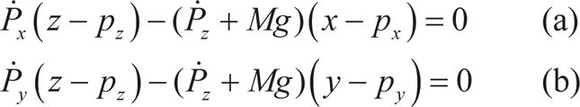
If the CM height z is set constant, the equation (12) becomes a cart-table model in term of EZMP [10]. However, to allow the vertical motion we choose a more general constraint as follows

or
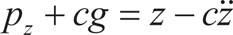
where c is a constant.
Substituting (15) into (12) and combining (16) gives us

where
The first two rows of (17) are the same as the constant height cart-table model (in terms of EZMP). The third row serves as a constraint. In this sense, equation set (17) is a natural generalization of the cart-table model to EZMP and to the 3D space of CM; here it is named the extended cart-table model It is very interesting to notice that the third row has the same linear form as the first two rows. This means all the motion planning or control methods available to the cart-table model are also applicable to our extended cart-table model. In this paper, we are especially interested in applying the preview control. Once the trajectory

The auxiliary EZMP and CM trajectories for different c values
EZMP can be chosen at a general surface not limited to VCP. Physically, EZMP is a point on a plane where the moment generated by gravity, inertia force and external force except ground reaction force is along the VCP normal vector. VCP (or VCS) is a reference surface which provides consistency between the EZMP prescription and measurement. More complex surfaces are also applicable. Whatever surface is used results in the same equation, (12) or (17). Mathematically, z-direction motion in (17) will affect how the constraint parameter c evolves with given pz. Only the z-direction motion evolves as given in (17); c is a constant and the EZMP equation remains linear. In particular, setting
Most of the inverted pendulum model-based motion planning methods cannot change the future ZMP in real time. The preview control of ZMP was used to tackle this problem [10]. In our case of planning a walk on rough ground, the extended cart-table model is used. In the sagittal plane (for example), the state space model in continuous time is formed as:
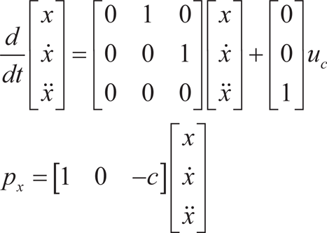
The equation (18) is discretized as:

where

T is the sample time.
For preview control, the performance index is given as:

where
By preview control theory, the optimal controller with preview time of np is given as [10, 25, 26]:

where np is the previewed length in dummy time points.
In the same way, the preview controllers for y and z dimensions can be obtained. Three preview controllers are implemented in x, y and z axes simultaneously. We call the controller group triple preview controller. It should be noted that in the z-axis controller,
The z-dimensional controller uses a mechanism that is similar to what is used in horizontal dimensions. The z-dimension controller guarantees the CM trajectory satisfies a specific constraint (Equation (15). Under the constraint, the x and y of CM goes as if there is no height change. Although the constant c somewhat limits the versatility of CM motion compared with the nonlinear optimisation method [21], the usage of the linear model decreases the computing burden and vertical CM motion is still considered.
In this section we will show the general framework of generating motion patterns on universal rough terrains using an extended cart table model and EZMP concept under preview control.
General Procedures for Pattern Planning
At a minimum, we need to assign the spatial gait parameters (step/stride length, width and clearance) as well as temporal gait parameters (gait cycle and occupancies of double/single support phases) to begin the walk motion planning. The foot landing position and time can be calculated accordingly. To judge stability, we give the concept of the virtual support polygon (VSP) defined as the convex hull encompassing the supporting foot/feet projections onto the VCP plane. For single support phase, the EZMP trajectory is designed assuming the largest stability margin, which means EZMP is located at centre of VSP polygon. For the double support phase, the EZMP trajectory is generated by linear interpolating in three directions simultaneously, given initial and terminal CoPs as boundary points. EZMP is constrained within the VSP polygon. Foot trajectories are calculated using spline interpolation considering the boundary locations and time of feet. Additionally, avoiding obstacles is also considered in calculating the foot trajectories. When all of the above is performed, the CM trajectory is generated using a triple preview controller (21) (similar in y and z dimensions) in Section 4 applied to extended cart-table model (17) in Section 3. The joint angles are calculated by inverse kinematics and fed to the robot.
EZMP Trajectory Prescription
We have proved in Section 2 that the EZMP follows the same dynamics equation as the ZMP equation (12) under constraint (9). Moreover, VCS (virtual contact surface) is chosen to be the VCP plane and the angular momentum around CM is neglected to eliminate constraint (9). Therefore, for the motion planning part, no change is made to the ZMP equation to adapt to uneven ground. However, if angular momentum is considered, EZMP must also satisfy constraint (9) exactly. In Assumption *, we have assumed the VCP is a plane passing three centres of contacting areas for stance foot and swing foot at lifting and landing. The desired EZMP trajectory is also required to lie in VCP to be feasible. During single support, we choose the desired EZMP to be at the contact centre of stance foot. During the double support phase, the EZMP are defined by linear interpolating of the contacting centres of both supporting feet. It should also be noted that the VCP definition should be the same for EZMP planning and measuring/calculating.
Generating CM Trajectory by Preview Control
Upon the prescription of the EZMP trajectory, preview controller (21) can be applied to model (17). Note the auxiliary counterpart
EZMP Measurement
Although EZMP is defined on a virtual plane (VCP), it can only be measured from the pressure sensors mounted under the foot bottom as well as the ankle torque feedbacks. Like the planned EZMP mentioned above, the measured EZMP should also conform to the Definition 2 and Assumption *.
Let
or

where

Multiply both sides of (23) by a matrix

where
Let the first two elements of

where Γ and Γi (i=1, 2) are sub-matrices consisting of the first two rows of
Additionally, the EZMP
or

where
Concatenate Eq. (25) and (27), we obtain:

where
It is easy to prove rank(Ψ) = 3 if and only if
If
If

where

It is easy to prove, with the z-component of
Our proposed motion planning method is tested using a simulated Atlas robot shown in Figure 3, configured with real robot specification (https://bitbucket.org/osrf/drcsim/src/c69ecab26a55/ros/atlas_description/urdf/). The Webots software is used for simulation (http://www.cyber-botics.com/).

Atlas robot
Four FSR sensors are attached beneath each foot to measure pressure. The ankle joint torque feedback is also used to calculate the frictions. The extended ZMP are calculated from pressure and friction measurements. The simulation is run on a computer with Intel Core i7 CPU of 2.67GHz and 8G memory.
The EZMP concept and extended cart-table model are used combined with preview control. The general procedure of pattern planning is as follows.
The main goal of this paper is to construct a general framework to plan walking on complex terrains. Thus, we will consider planning patterns for climbing stairs at first and then rough terrains. Climbing stairs can be taken as the basis for general rough terrain walking. Currently, the landscape is assumed to be exactly known.
The constraint constant in the extended cart-table model is c=0.0861 s2. The walk stride length and step wide are 0.36 m and 0.2 m. Foot clearance is determined by the height of obstacles and desired landing position.
Considering that the centroidal angular momentum is neglected in walk planning, the modelling error can deteriorate the stability. Therefore, a walking stabilizer is indispensable. The sudden change of ZMP reference by the stabilizer will cause a large tracking error of preview control in the same control loop. We find that the tracking is not as sensitive to system state (CM motion) change as to (E-) ZMP change in our case. Therefore, we use a modified version of the typical stabilizer using a linear inverted pendulum [27]. The resultant controller is formed as follows (x-dimension):

where
The whole landscape is shown in Figure 4. The upstairs are constructed with 0.08 m increment. The top surface of every stair is flat with an area of 0.32×0.2 m2 encompassing the robot foot bottom. The robot walks from level floor up stairs. Walking cycle is 1.2 s including 2/3 single support phases and 1/3 double support phases. The sampling time is 10 ms and preview period is 2 s which is generally long enough to achieve good preview control. Considering Equation (21), weighting matrix
Landscape of stairs

EZMP prescription for walking on stairs
The walking planning method in this paper (with dynamic constraint of CM) is compared with a comparison planning method of which the vertical motion affects the horizontal motion. To generate the vertical CM motion in the comparison method, we use a logistic function-based interpolator from [28] with boundary points. The logistic function interpolator is defined as:

where t is time and z is vertical CM position. Δt = tn −t0. Subscript 0 and n denotes initial and terminal condition. This interpolator maps the typical logistic function from the infinite domain of definition to a finite interval [t0, tn].
The EZMP tracking in 3D view without and with dynamic constraint are shown in Figures 6 and 7. x =0∼0.18 m and x=0.18∼0.72 m correspond to the walking on level floor and upstairs. The measured EZMP in blue lines are constrained in the hexagons and the tracking error of EZMP

EZMP tracking in 3D view not constraining vertical CM motion

EZMP tracking in 3D view dynamically constraining vertical CM motion

Motion planning ignoring (a, c and e) and considering vertical motion effect (b, d and f)

Motion tracking ignoring (a, c and e) and considering vertical motion effect (b, d and f)
Snapshots taken for walking upstairs with vertical motion effect ignored (a and c) and considered (b and d)

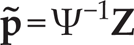
Rough terrain
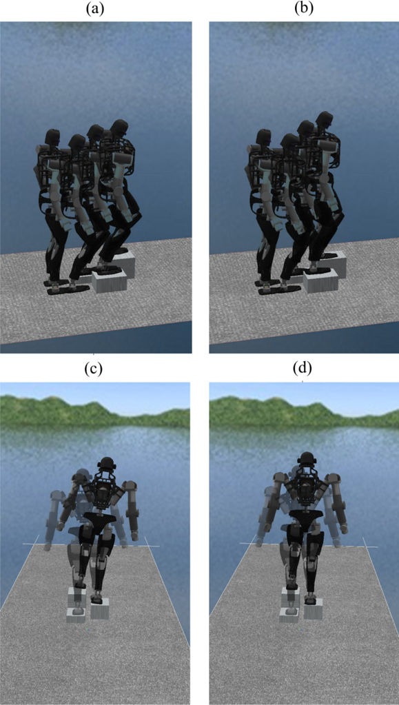
As shown in Figure 11, the stones on which the robot walks have a top surface of 14° inclination at most. The height of stones varies greatly from 0.12 m to 0.32 m. The stone slopes have a rotation angle around the vertical direction from −15° to 15°. To allow a large contact area, the foot posture is planned to be parallel with the stone top surface pointing at the long side direction of stone. The walking cycle is 2.4 s including 2/3 single support phases and 1/3 double support phases. The sampling time is 20 ms and the preview period is 2 s. The desired and measured EZMPs are shown in Figure 12. As can be seen, the EZMP in all three dimensions is tracked accurately, except around 10.8 s and 15.1 s.
EZMP tracking for walking on rough terrain
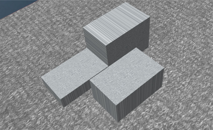
The outlier points in Figure 12 can be explained by the large condition number of Ψ around 10.8 s and 15.1 s, shown in Figure 13. Although the outlier points fall outside of support polygons, the instability cannot be indicated using the erroneous EZMP value. The stabilizer is switched off at those points to rule out the inaccurate measurement. The robot can successfully walk through the rough terrain as shown in Figure 14.

Rank and condition number of matrices for walking on rough terrain

Snapshots taken for walking on rough terrain
(The video can be accessed at: https://www.youtube.com/watch?v=6QypO7TP3gs).
In this paper, we established a general framework of planning walks on complex terrains with vertical dynamics incorporated. Two problems were solved: ZMP is undefined on uneven ground and cart-table model does not consider vertical dynamics.
An EZMP concept was proposed to extend ZMP to universal uneven terrains. The EZMP is defined on a general surface (VCS). For simplicity in this paper, VCS was chosen as an inclined plane (VCP) passing contacting centres of the single supporting foot and swing foot at liftoff and touch-down. By adding constraint (9), the EZMP dynamics equation was simplified dramatically. The EZMP can be used to judge stability on rough terrain by checking if the EZMP is within the convex hull encompassing footprint projections of supporting feet onto the VCP plane. The extended cart-table model was proposed with vertical dynamics rather than constant height as a constraint in the cart-table model. In this way, the new model preserves the linear form and allows vertical motion. A pattern generator was established by applying triple preview controllers to the extended cart-table model based on EZMP. We also presented the method of measuring EZMP calculated from pressure and friction measurements. Friction is indirectly measured from pressures and ankle joint torques. Simulation examples of walking on stairs and rough terrain were presented. The walking planning method on complex terrains was proved effective by impressive walking with good tracking of EZMP.
Our future work will include how to generalize the VCP plane to a general surface (VCS), which can be changed to manoeuvre the CM motion to keep the robot within the configuration space (determined by link lengths and joint rotation limits). On the other hand, more versatile motions can be achieved.
Footnotes
8.
This work was supported by the National Natural Science Foundation of China (grant number 61071057) and the University Innovation Team of Liaoning Province (LT2014006). We sincerely thank Christopher G. Atkeson and Siyuan Feng for the detailed explanations of the ideas in their paper. We sincerely thank Shuuji Kajita for answering the questions to his paper.