
Abstract
Existing sampling-based footstep planning method for biped navigation used an intermediate static posture for footstep transition. However, when adopting this approach, the robot is sensitive to modeling error and external environments, and also the transition between different gait patterns is unnatural. This article presents a central pattern generator approach to footstep transition for biped navigation. First, this approach decomposes the biped walking motion into five motion types and designs central pattern generator network for all joints of legs accordingly. Then, the central pattern generator parameters are simplified and the relationship between these parameters and footstep transition is formulated. By modifying the central pattern generator parameters, different walking gaits can be obtained. With sensing feedbacks, self-adaption walking on irregular terrains, such as walking on unknown sloped terrains and flat floor with tiny obstacles, is realized. Experiments were conducted both in simulator and on a physical biped robot. Results have shown that the proposed approach is able to generate gesture transition trajectory for biped robot navigation and realize a self-adaption walking for irregular terrains.
Introduction
With better mobility and an anthropoid shape, biped robots are expected to assist human activities in daily environment, such as offices, hospitals, or at homes. To execute senior tasks in human-living environments, an effective footstep planning method for biped navigation is increasingly demanded.
Previous navigation methods for biped robots can be roughly classified into two aspects. The first method is a deterministic sampling-based footstep planning, which is effective in open environments. 1 –3 The second method is a random sampling-based method to goal-bias the footstep planning, which can accomplish navigation in some special environments, such as fields with local minimal or narrow passages. 4 –6 Since human-living environment is complex and varied, in many research, the second method has been used for humanoid robot global navigation.
The framework for biped robot navigation is normally composed of three parts, as shown in Figure 1. The first section is the environment sensing (Kinect used), which is used to get the surrounding environment. The second section is a randomized search tree, which can generate footstep sequences. And the last section is a footstep transition model, which supplies an element footstep library as the searching manifold. Intermediate static posture (ISP) is a traditional footstep transition model that is planned offline and used online. 6 Although ISP could decrease the computation complexity, the step is processed in advance and sometimes the transition between different gaits seemed to be unnatural.

Sampling-based footstep planner for biped robots. 4
Biological studies of animals suggest that the central pattern generator (CPG) existing at the spinal cord combined with reflexes receiving adjusting signals from the cerebrum and the brain controls the animals motion (such as walking, heartbeat, and breathing). 7 CPG control methodology was built to accomplish the similar function of CPG in animals, and this methodology has become a powerful tool for generating a locomotion pattern for biped robot in recent years. 8 –11 CPG control methodology usually does not need precise robot model and makes walking motion be more natural. Since the CPG can combine with feedback signals easily, many adaptive locomotion has been obtained based on the CPG method. In order to address those issues of current methods using ISP, CPG was used in our work to provide an effective and adaptive gesture transition trajectory for biped robot navigation.
However, tuning parameters of the CPG method is a difficult task for biped robot navigation because of a large number of parameters and the lack of relationship mapping between parameters and dynamic behaviors. So, our subjects in this research are (1) providing an effective gesture transition trajectory for robot footstep planning. Different walking gaits were obtained, which contain walking forward, backward, lateral, and rotation; (2) simplifying the parameters of CPG and building a certain relationship between the parameters of CPG and the position of swing foot; (3) changing parameters of CPG by values of sensors to adapt the irregular terrains.
The rest of this article is organized as follows. The section “Gesture transition trajectory based on CPG” describes the role of CPG in the footstep planning and the process of generation CPG. The results of experiments conducted both in simulator and physical robot are given in section “Experiments.” At last, the conclusion of this article along with a discussion on our future work is given in section “Conclusion and future work.”
Gesture transition trajectory based on CPG
In order to adopt the CPG method to generate gesture transition trajectory for the biped robot navigation, the corresponding relationship between CPG parameters and the locomotion should be constructed. After getting the footstep sequences, relationship would be required to directly guide the position of the landing foot. There are two kinds of CPG control approaches: to allocate CPG units at each joints of the legs to demonstrate desired locomotion or to allocate CPG units to partial variables to simulate periodic characteristics of walking gait. 12 No matter what kind of CPG control approach we take, the relationship between the parameters of CPG and the locomotion is not clear, and it is hard to obtain a sequence footstep.
In this study, we aimed to build a CPG control method for biped robot and obtain corresponding relationship between the parameters of CPG and the locomotion. So, first, we will analyze the attribute of walking motion, and on this basis, the CPG oscillators will be built. After that, adaptive walking with feedback will be obtained.
Although many kinds of biped robots have been developed nowadays, such as ASIMO, ATLAS, QRIO, and NAO

Biped robot model. (a) The lower limb joints of a biped robot. 13 (b) Notations for joint angles.
In our research, we modeled the basic walking locomotion of biped robot into five types of motion in the three planes according to the motion attribute, as shown in Figure 3.

Five motion types of basic walking locomotion. (a). Side-to-side motion (I), (b) stepping side motion (II), (c) forward motion (III), (d) rotating motion (IV), and (e) lifting motion (V).
Trajectory regulator
To generate any footsteps for biped robot walking, we need to construct a trajectory regulator for each motion types.
Motion types in lateral plane
There are two types of motion in lateral plane, the side-to-side motion-I (Figure 3(a)) and stepping side motion-II (Figure 3(b)).
Motion-I is one of the crucial motions for biped robot walking. When swing legs execute motion in lateral plane and transverse plane, the center of mass (COM) should concentrate on the supporting foot. The side-to-side motion aims to realize the transition from one leg to another one. One step for human corresponds to a cycle for robot, so motion-I should be described as a periodic function. As we all know, sin function is a common periodic function, and it can be used to describe the side-to-side motion. 14 However, only one basic sin function would always lead to incomplete transfer of the COM. When studying on human walking, we know that a whole walking cycle can be divided into a double-support phase (20%) and a single-support phase (80%). 15 Therefore, instead of using one single sin function, we prefer to combine tanh function with the periodicity of sin function, which will meet the requirement of double-support phase and single-support phase of one walk. For side-to-side motion-I, hip roll joint and ankle roll joint are required, thus motion-I can be formulated as

where A I is related to the maximum distance of COM in lateral plane.
To execute walking in lateral plane, stepping side motion-II is performed by the unloaded leg. The abduction/adduction of unloaded leg in lateral motion only happens in the single-support phase, because in double-support phase, it holds the state of abduction/adduction. So, motion trajectory function of motion-II also uses tanh function, but with half cycle to ensure the stepping side motion is conducted after the transition of COM. Hip roll joint and ankle roll joint are required, thus motion-II can be formulated as
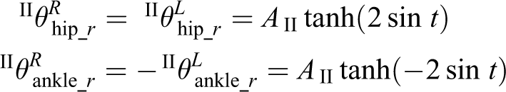
The unloaded leg will land the floor, when
Motion types in transverse plane
There are two types of motion in transverse plane, forward motion-III (Figure 3(c)) and rotating motion-IV (Figure 3(d)).
A one-dimensional example radius portrait of a morphed amplitude controlled oscillator. The desired limit cycle is
We still use sin function for forwarding motion. Similar to stepping side motion, the forwarding motion also happens after COM transits to supporting foot. In motion-III, six joints of legs are used to walk forward, hip pitch, ankle pitch, and knee pitch, so motion-III can be formulated as
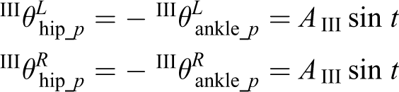
similarly
To keep upper body upright, the knee joints should meet

In forward motion,
In the rotation motion, hip yaw pitch joints are used, so motion-IV can be formulated as

similarly,
Motion types in sagittal plane
There is one type of motion in sagittal plane, lifting motion-V (Figure 3(e)).
Lifting motion makes the foot achieve vertical clearance, which is another crucial motion for walking. Six joints are used for lifting motion: hip pitch, ankle pitch, and knee pitch. So motion-V can be formulated as
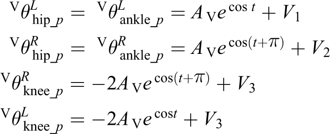
where
In the aforementioned five types of motion, side-to-side motion and lifting motion are the basic motion for locomotion. Combining with another three types of motion, these two basic motions can generate any footsteps contained in the reachable region of swing foot. The values of


Hence, trajectory regulator in footstep planning for biped robot navigation can be generated.
Central pattern generators
CPG control system is a dynamical system, which is mathematically composed of coupled nonlinear oscillator. 16 There are three common oscillators: two-dimensional nonlinear oscillator (Hopf oscillator), neural network oscillator (Matsuoka oscillator), and dynamical movement primitives (Morphed oscillator). Hopf oscillator can only output a very simple curved line such as sinusoid. Matsuoka oscillator has too many parameters and the process of finding appropriate parameters is a tough task. Compared to the Hopf oscillator and Matsuoka oscillator, morphed oscillator can output arbitrary periodic signal and have a few parameters. So, the morphed oscillator 17 was used in this article.
The start of output from the original morphed oscillator is always unstable, which could lead biped robot to fall; in order to improve its output performance, we define a modified morphed oscillator as


where r is the phase,
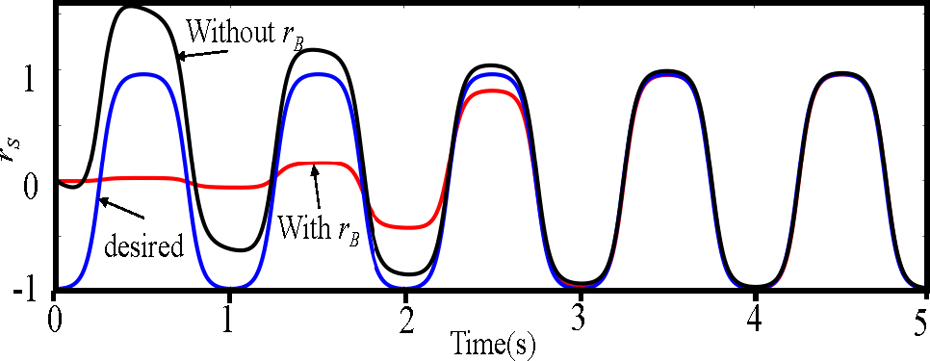
The outstanding feature of the modified oscillator is that it can learn or follow a known attribute. Figure 4 illustrates a one-dimensional example radius portrait of a morphed amplitude controlled oscillator, in which, the blue line is the desired trajectory, whose function is
Adjustable midpoint is another important feature, since the midpoint of the oscillator is related to feedback control in section “Adaptive walking with feedback.” A real-time smooth transition of midpoint is a pressing requirement. Without handling value o, the transition of midpoint is lagging, as shown in Figure 5(a), which would lead robot to tip up because of lacking real-time adjusting for disturbance.

Comparison of midpoint adjustment performance: the value of midpoint (top). Blue curve shows the original curve and the changed curve (bottom). (a) Without S function,
To improve the real-time performance, S function is used.

where
Adding S function can fasten the transition of midpoint, and the result is given in Figure 5(b).
Adaptive walking with feedback
When the biped robot walks forward from plat terrain to incline terrain, without adjusting, the center of gravity will move forward or backward accordingly. Once the position of the center of gravity exceeds the stable support area, the balance will be broken. By adjusting the angle of joints and the step length, the aforementioned situation can be avoided.
11
In CPG control system, the oscillator frequency controls the speed of motion, the values of
Normally, the robot body was kept in an upright position when walking on plane. The gyrometer and accelerometer sensor of the robot can monitor the state of the robot body in real time. The value of parameter o, by controlling the oscillator midpoint position of knee joints motion, can adjust the body inclination in sagittal plane. The value of o is set proportionally to the difference between the reference inclination Angle (−0.03 to 0.13 rad) and the current body inclination estimated from the gyrometer sensors,

where
The value of

where
Experiments
We validate the CPG control approach both in simulation and on physical robot NAO. Before the experiment, the simulated and physical robots need a definition for initial state. The Choregraphe [SoftBank Robotics, Ver. 2.1.4] software provides a pose library for NAO robot. We borrowed the Standinit Posture
18
from pose library in Choregraphe as initial state, and the joint values in the initial Standinit Posture is given in Table 1. So,
Joint values in initial Standinit posture.

An effective gesture transition trajectory
As mentioned earlier, the position of landing foot is related to the parameters of CPG. This relationship is determined by robot model and the initial state of the robot. The values of


where
Then, the footstep planning and CPG model composed a dual-thread control system. The footstep planning plans in every walking cycle. If the next step is different from current one, the values of
Stick of the NAO model in the case of
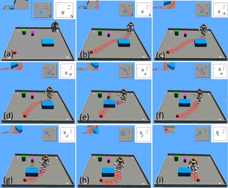
CPG controller generates an effective gesture transition trajectory for sample-based footstep planner. (e)–(g) the position of obstacles was changed and (h)–(i) the position of the target was changed. CPG: central pattern generator.
Adaptive walking on slope terrain with feedback
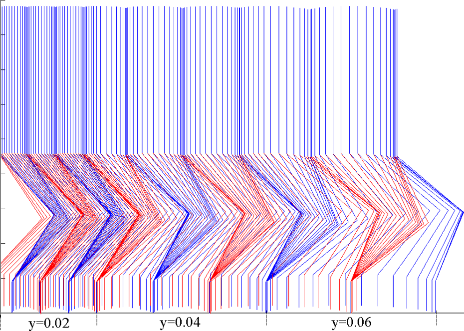
In this section, slope-adaption walking simulation experiment is conducted in 45 s length and the snapshots are shown in Figure 9. The robot walked from flat terrain to uphill, then to the flat, to the downhill, and at last to the flat again. The CPG parameters and the corresponding step size for the slope-adaption experiment in simulation are given in Table 2. When the robot walked from the flat terrain to the uphill, the gyro monitors the tip at first. To keep the stability walking for the robot, midpoint of the ankle pitch joints was decreased and the step size turned from 6 cm to 4 cm. When the robot walked from flat terrain to the downhill, midpoint of ankle pitch joints was increased and the step size turned from 6 cm to 8 cm. Figure 10 shows the control signals for the left leg joints in simulation experiment.

Simulation experiment. (a) and (b) NAO walked form flat terrain to uphill, (c) and (d) NAO walked from uphill to flat terrain, (f) and (g) NAO walked from flat terrain to downhill, (h) and (i) NAO walked from downhill to flat terrain. The dip of the slope is
The control signals for the joints of left leg.
CPG parameters and corresponding step sizes for the slope-adaption experiment in simulation.

CPG: central pattern generator.
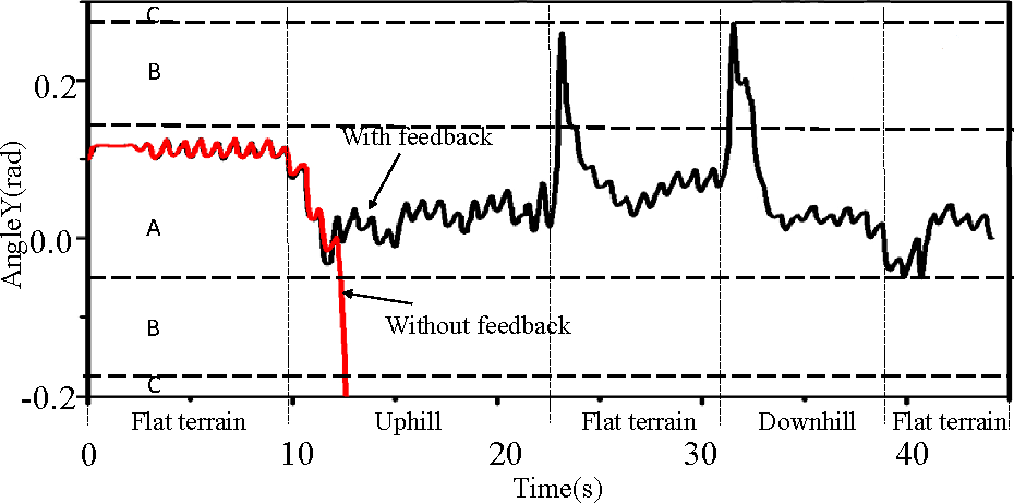
Figure 11 shows the change of value of AngleY, which represented the changes of body attitude in y direction. The red curve shows the robot walking without any feedback and the black curve shows the robot walking with feedback.

The change of robot attitude feedback. The red curve shows the value of gyro in y direction for the robot walking without feedback and the black curve describes the value of gyro in
Physical experiment
In the simulated slope walking experiments, the proposed control method was proved feasible. To test the real robots adaptive walking performance, we downloaded the program to a real NAO robot. The robot can walk stably on the slope in which the dip was changed. Figure 12 shows the snapshot of the slope walking experiment. Figure 13(a) and (b) shows the value of gyro in y direction for the robot walking on uphill and downhill. With the change of dip, the value of gyro was in a range. No mater walked on the uphill or downhill, the robot walked stably. With the proposed control method, the robot also can walk on the terrain with some tiny obstacles. The snapshots of walking on tiny obstacles experiment are shown in Figure 14.

Side-view snapshots of the NAO robot walking on the slope terrain.

The value of gyro in y direction. (a). Robot walking on uphill and (b) robot walking on downhill.

NAO walks on terrain with a ruler and an earphone.
Conclusion and future work
In this work, the CPG-joint control method was presented to replace ISP to offer a new method of gesture transition trajectory in footstep planning for biped robot navigation and realize a self-adaption walking for irregular terrains.
The advantage of the proposed method is that a whole walking motion was decomposed into five periodic motion types, and two of them, motion-I and II, are basic motion types for walking motion. By combining two basic motion types with another three motions, it can easily reach any walking motion, for example, walking forward, walking lateral, and turning. Then, the joint motion trajectories were generated to build the trajectory regulator according to the attributes of motion types. This relationship between joint motion trajectories and the position of swing foot is built successfully. This relationship makes landing foot to reach anywhere in the reachable region. The amount of parameters of CPG is small, in which three parameters are adjustable, and the rest are constant. At last, the feedback control ensures the robot walking on irregular terrains, such as walking on unknown sloped terrains and flat floor with tiny obstacles. The simulator and physical experiments proved the feasibility of the proposed CPG control method.
Our future interests include (1) optimizing the CPG control method from energy efficiency and building more complex feedback control, (2) applying the proposed method to more challenging tasks, such as terrain with larger slope, and (3) applications on other types of biped robots.
Footnotes
Declaration of conflicting interests
The author(s) declared no potential conflicts of interest with respect to the research, authorship, and/or publication of this article.
Funding
The author(s) disclosed receipt of the following financial support for the research, authorship, and/or publication of this article: This work was supported by National Science Foundation of China (51305436, 61403368), Guangdong Natural Science Foundation for Distinguished Young Scholars (2015A030306020), Major Project of Guangdong Province Science and Technology Department (2014B090919002), Fundamental Research Program of Shenzhen (JCYJ20140901003939038, JCYJ20140417113430639), Research Project of Shenzhen (GJHS20160331190459402), Shenzhen High-level Oversea Talent Program (KQJSCX20160301144248) and Youth Innovation Promotion Association, Chinese Academy of Sciences (No. 2015301).