
Abstract
In surgery with a master-slave type of surgical robot, an anisometric interface is often used. The working range of the master side is limited, so repositioning is required. Any repositioning from the master side will disturb the robot's operation. In this study, an operation interface is proposed that uses only the operator's force input for translational directions. A force sensor is used to detect this input. A gimbal mechanism is mounted on the sensor which allows for rotation. The rotation accounts for the operator's input rotation, and as a result the mechanism can now match the input. This allows the operator to concentrate on the slave side and control the robot without repositioning. The authors developed the proposed interface to control the pneumatically driven slave robot. The block transfer experiments confirmed that the proposed interface has nearly the same performance as conventional interfaces.
Introduction
Recently, master-slave robotic systems have been implemented in surgical robotics [1–5]. These systems require enough dexterity to perform complicated tasks with high precision. It is also necessary for the surgeon to be comfortable with the use of the master manipulator.
One of the objectives of controlling a master-slave system is ease of use. This ease of use can be achieved by making the positions and the forces for the master and slave manipulators identical in the task coordinate system, regardless of the environment.
The Da Vinci system has an original master console [1]. The master manipulator uses a serial link mechanism. The DLR MiroSurge uses a Delta/Omega/Sigma series (Force Dimension, Switzerland) [6]. Furthermore, in the field of surgical robotics, commercial haptic devices are used for the master device. One such example is the PHANTOM series (SensAble Technologies, Inc., USA) [7].
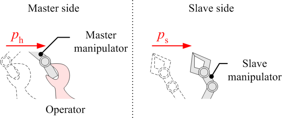
Human-machine interfaces like master manipulators can be divided into two categories: isometric and anisometric. An anisometric interface allows movement with varying degrees of resistance and uses displacement as the control input. These master manipulators use position control. The input is the position of the operator and the output is the position of the slave manipulator (Figure 1).
Anisometric devices have the benefit of providing proprioceptive feedback, for example a sense of body position and force display. However, these often require mechanically complex devices and are more expensive. In order to operate with high precision on the slave side, the translational movement of the operator's hand must be scaled down. This scaling from the master to the slave is another drawback.
Overview of an anisometric device with position control

Overview of an isometric device with rate control
This drawback means a larger workspace is required for the master, but this is not always available. As a result, the operator must reposition the master using a device like a foot pedal which disconnects the master from the slave.
The other type of interface, an isometric interface, does not allow for movement of the operator. The control input is an applied force or torque. Generally, velocity control is better for isometric devices (Figure 2) [8]. These devices lack proprioceptive capability, but have the advantage of not being limited by the master side workspace. Another advantage is that these devices can significantly reduce an operator's fatigue [9].
In this paper, we proposed a master manipulator that utilizes a combination of these control techniques. The master has a total of six degrees of freedom (DOFs). An isometric device and velocity control are used to control the 3DOFs translational motion. An anisometric device and position control are used to control the 3DOFs' rotational motion, using a gimbal mechanism. As long as the range of rotation is large enough, the proposed master has the advantage of not needing to reposition when controlling the slave manipulator. The authors have developed a master device to control a 6DOFs surgical manipulator [10,11]. The effectiveness of this proposed master device is confirmed experimentally.
The paper is organized as follows. Chapter 2 describes the proposed master manipulator. Chapter 3 describes the surgical robot and the master-slave system developed by the authors. Chapter 4 details the experimental setup and method. Chapter 5 reports the experimental results and discusses them in detail. Chapter 6 is the conclusion.
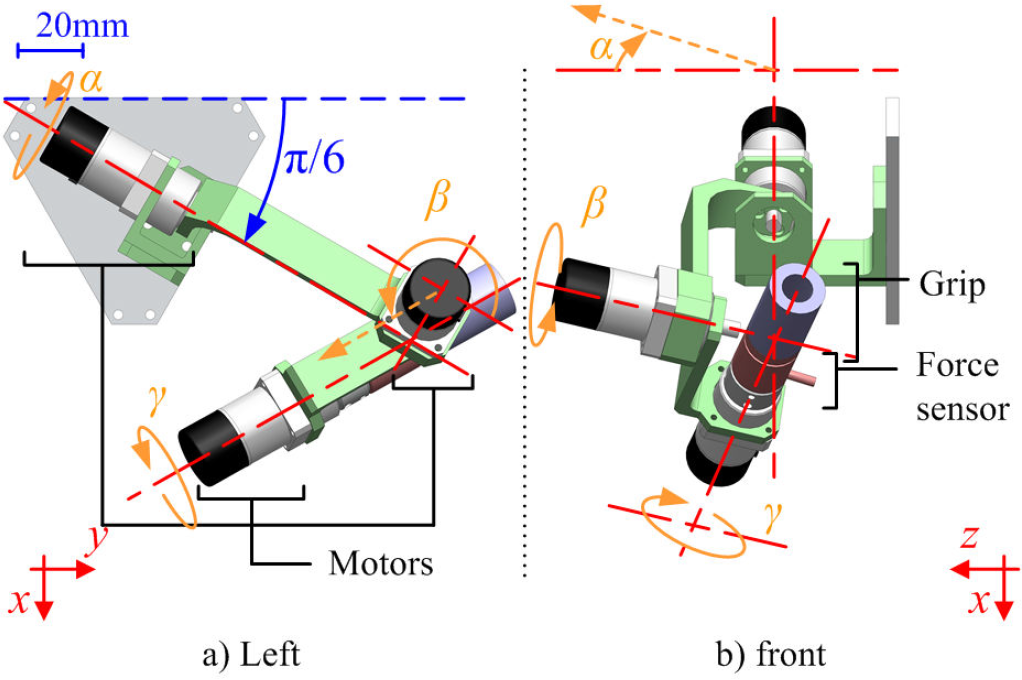
Overview of the master manipulator
Ranges of motion (Unit: deg)

Hardware
We have designed a master manipulator with 6DOFs as shown in Figure 3. The master manipulator incorporates a 3DOFs gimbal mechanism. A six-axis force sensor is mounted at the bottom of the grip. AC servo motors with encoders and reduction gears are located on each axis of rotation. The ranges of motion are shown in Table 1. The full length of the master manipulator is about 170 mm.
The force given by the operator is the input for the translational motion control. The operator grasps the grip, and can apply a force to the master manipulator. This force is measured by the force sensor.
In addition to the isometric component, anisometric position control is used to control rotational motion. The inherent impedance of the master manipulator can be altered via impedance or admittance control. Admittance control is a method where the position of the master manipulator is controlled by an actuator. The position is calculated from the measured operator's input force/torque via a transfer function. This method does not consider the weight and impedance of the device. Thus, in this application, admittance control was used for the rotational motion.
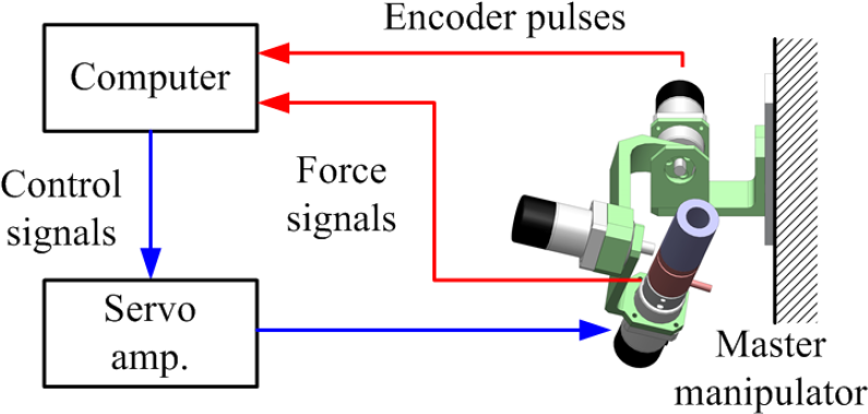
Signal flow in the master manipulator. Red lines indicate input signals and blue lines indicate output signals.
Figure 4 illustrates the electrical signal flow in the master console. First, an operator applies force in order to move the slave manipulator. The signals from this force and rotational displacements are transmitted to a PC. Reference translational and rotational positions are calculated by the PC. In order to update the rotational motion of the master manipulator, the control signal is sent to the servo amplifier and the servo motors.
The following section explains the specifics of the control process.
Block diagrams of the control are shown in Figure 5. The first step for the translational motion control is the conversion of the operator input force fh to the master input force f m . The operator cannot sense a force in the dead band of force. Therefore, it is important that the slave manipulator does not move when the operator input |fh| is smaller than the threshold fth. This results in a piecewise function for the master input force; f m is given by the following equation (1).


Block diagrams (Top: Translational motion control, Bottom: Rotational motion control)
Then, we will calculate the target velocity
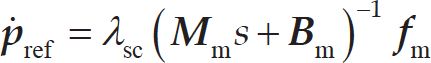
Here,

More force is required to obtain the same speed when moving forward or backward than when heading upward, downward, left or right.
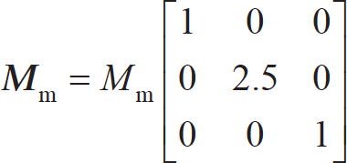
Applying the linear scaling ratio, λsc, results in
The rotational control is shown in the bottom section of Figure 5. Input moment

Then, using the Jacobian matrix
Slave manipulator (Ibis)
The authors have developed a slave manipulator for laparoscopic surgery, called Ibis [10] (Figure 6). Ibis has a total of seven degrees of freedom in order to the control the tool tip (3DOFs in translation, 3DOFs in rotation and 1DOF in the gripper). Ibis consists of a supporting manipulator and a detachable forceps manipulator.
In Ibis, pneumatic actuators rather than electric motors are used to detect external forces. These pneumatic actuators are able to detect these forces based on pressure values and therefore do not require a force sensor. Using pneumatic cylinders with high power-to-weight ratios eliminates the need for a reduction gear in order to achieve both adequate torque and high back-drivability. The use of pneumatic cylinders also makes the system smaller and lighter.
The supporting manipulator has a total of four DOFs: three rotational DOFs around the inlet of the trocar cannula and one translational DOF along the axis of insertion. Parallel link mechanisms provide a remote centre so that the pivot point at the trocar cannula is mechanically immovable without direct assistance. Rotation of the forceps manipulator in the horizontal direction is accomplished by transmitting the output to several vane-type pneumatic motors with timing belts. Rotation in the vertical direction is achieved by converting the linear motion of the pneumatic cylinder into rotational motion using a slider-crank mechanism. The translational motion along the axis of insertion is directly driven by the pneumatic cylinder.

Overview of the slave manipulator (Ibis)

Overview of the forceps manipulator with flexible joint
Figure 7 shows an overview of the forceps manipulator [11]. The tip section has 2DOFs: a flexible wrist joint using a machined spring and a pneumatic gripper driven by air pressure. A key advantage of this combination is that the motions of the gripper and the bending joint will never interfere with each other. The driving section is equipped with four pneumatic cylinders. Linear actuations of the cylinder rods through super-elastic wires connected to the tip joint allow the joint to bend in any direction.

Signal flow of entire master-slave robotic system
A signal flow diagram of the entire master-slave robotic system is shown in Figure 8. UDP is used for communication between the master system and the slave system. On the master side, the position and the rotation references are obtained. After the slave side receives the data from the master side, the master motion is transformed into the slave coordinates by solving inverse kinematics. The servo-frequency of the slave side is updated at 1 kHz.
Using this system, we investigated operability (the functionality, capability and limitations) of the proposed master manipulator by conducting the following experiments.
Experiment
Block transfer task
A pegboard is often used for laparoscopic surgical training and evaluation [12]. Lum et al. adapted the task in order to evaluate robotic surgery [13]. Based on this, the operability (functionality, capability and limitations) of the proposed master manipulator was evaluated using a block transfer task.
A right-hand side master-slave manipulator and three blocks on the pegboard were used in this experiment. The master side primarily consists of two components. One is the 2D screen and the other is the master manipulator. Both are shown in Figure 9. Video of the surgical site is acquired by a PC connected to a 2D web camera (HD Webcam C910, Logitech International S.A.) and then transmitted to the screen.
Experiment design
Three blocks are first arranged on the left-hand half of the array of pegs. The initial position of the forceps is the top of the first peg on the left. Subjects must use the gripper to grasp each block, lift the block from its peg, and transfer it onto the same numbered peg on the right-hand side of the board. The subject must then repeat the left-to-right transfer for all three blocks, followed by a right-to-left transfer of all three blocks without pausing in between. The traces while transferring the blocks during the experiment are shown in Figure 10.
For each trial, a three-minute time limit was given rather than measuring the task compilation time. After conducting the timed trial, we decided to evaluate operability by counting the number of blocks transferred within a time limit. Subjects were asked to transfer the blocks as quickly as possible.
During the experiment, the gripper was actuated by pushing a button with the left hand (‘A’ key on the keyboard). This was done to eliminate any effect of grasping force on the experimental data collected during the operation.
If a subject dropped a block, the subject was ordered to move on to the next block. While the subject was transferring the next block, the dropped block was placed back on one of the pegs on the left-hand side of the pegboard by the person conducting the experiment. The number of dropped blocks was not recorded.

Overview of experimental setup (master side)

Experimental procedure. Lines indicate routes. An operator has to transfer the blocks along the routes. At first, the operator begins to move Ibis along the green line. Next, along the red lines, the operator transfers the blocks from left to right. Then, along the blue lines, the operator transfers the blocks from right to left. A solid line means a movement with a block, and a broken line means a movement without one.
The subjects trained for more than 15 minutes in order to familiarize themselves with the master manipulator and the task. After the training, the subjects performed 10 repetitions of each task with the master manipulator. The subjects were given breaks of approximately one minute between each trial while the person conducting the experiment set up the next trial.
Five subjects participated in this experiment. The subjects consisted of four men in their 20s and one man in his 30s.
Table 2 shows the control parameters of the master manipulator used in the experiment. All parameters were determined by trial and error. The linear scaling ratio λsc was set first at the value 1.0. Other parameters were then decided. In this paper, three values of λsc (0.5,1.0,1.5) were tested.
PHANToM Desktop (SensAble Technologies, Inc.) was used as a baseline control interface to compare and evaluate the operability of the proposed master manipulator. The control parameters of PHANToM Desktop were also determined by trial and error. The motion scaling ratio was set to 0.9. In order to maintain consistent testing conditions, the gripper actuation was also controlled by pushing a button (‘A’ key on the keyboard) with the left, as in the proposed master manipulator. The control signal delay of the master-slave system was negligible.
Control parameters of the master manipulator

Control parameters of the master manipulator
Figure 11 shows the tracking data for Subject A while transferring the blocks using the proposed master manipulator. In this instance, the linear scaling ratio was set to λsc = 0.5 and it was the subject's 10th trial. The upper and the lower figures indicate the translational position and the translational force, respectively. It is apparent that the motion of the master side showed no position change.
Figure 12 shows the translation motion tracking data when Subject A was transferring the blocks using PHANToM Desktop. It was again the subject's 10th trial. Comparing the results to those in Figure 11 confirms no noticeable difference in the trend of the translational motion.
A comparison of all of the trials and the number of blocks transferred for both Subject A and Subject E are shown in Figure 13. The graphs confirm that there was no noticeable learning effect during the experiments. We used all of the trials to calculate averages and evaluate the operability due to the lack of a learning effect or upward trend in performance as a function of time.
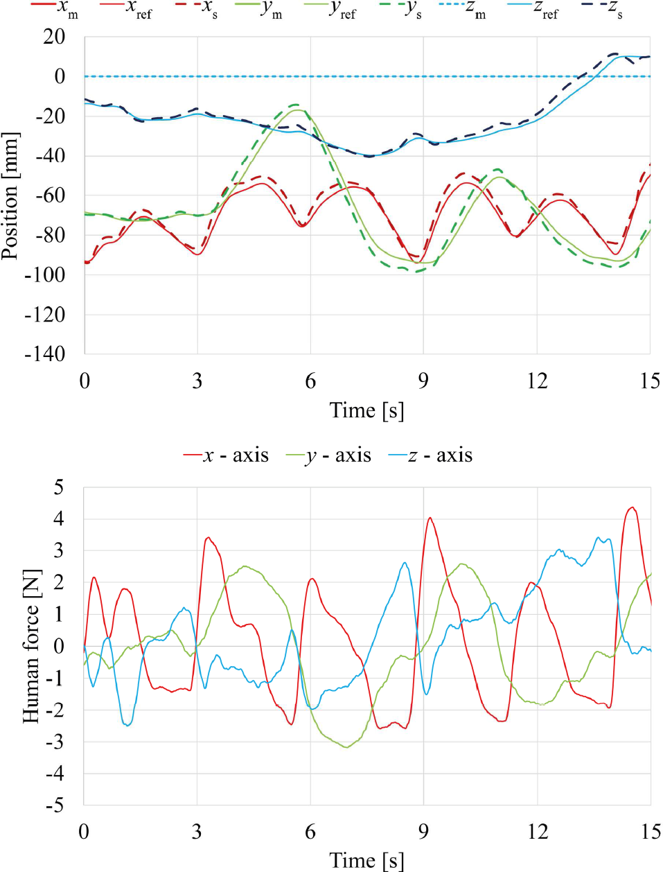
Tracking data when Subject A was transferring the blocks using the proposed master manipulator in the case of λsc = 0.5 and 10th trial. Upper: Translation motion. Lower: Input force given by the operator.

Translational motion tracking data when Subject A was transferring the blocks using PHANToM Desktop, Subject A, 10th trial
Figure 14 shows the experimental results. Each bar indicates the average number of blocks transferred for a specific set of parameters. The brown bars are the results for the proposed master manipulator. The blue bar is the result for the PHANToM Desktop.
With the exception of Subject A, the other subjects had the best performance when λsc was 0.5 for the proposed master manipulator. The gaps in performance for the different values (λsc = 0.5 vs 1.0, 0.5 vs 1.5) are significant.
Compared to the PHANToM Desktop, the proposed master manipulator had very nearly the same performance when λsc was 0.5. However, Subjects B and C show a different trend. Both Subjects B and C transferred more blocks using the proposed master manipulator than using the PHANToM Desktop.

The number of blocks transferred in 10 repetitions of the task. The upper figure is the case of Subject A. The lower figure is the case of Subject E.
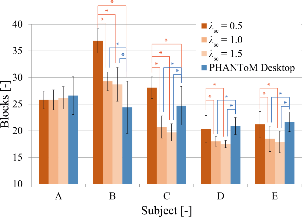
Block transfer task result. The average number of blocks transferred. The asterisk (*) indicates a pair with a significant difference (Significance level = 5 %).
Subject A transferred almost the same number of blocks under all of the conditions. One point to emphasize is that in the case of Subject B, performance was significantly improved when using the proposed master manipulator for all of the λsc values.
In this paper, we have developed a master manipulator that utilizes a combination of input control techniques. The master manipulator uses an isometric velocity control technique for translation and an anisometric position control technique for rotation.
The data from the block transfer experiment show that the subjects were able to operate the surgical robot using both the proposed master manipulator and the PHANToM Desktop with similar effectiveness. Using the proposed master manipulator when Asc was 0.5 resulted in nearly the same performance as compared to the PHANToM Desktop.
The future work will include:
Evaluating the effectiveness and the operability of the master manipulator when challenged with more complicated tasks
Improving the accuracy and operability of the master manipulator
Implementing a pseudo-force display for the master manipulator
First, we will challenge the master manipulator to complete more complicated tasks, such as knot tying, and compare its effectiveness to that of conventional manipulators.
Secondly, we will improve the translational control algorithm to improve accuracy and operability. One possibility would be to thoroughly consider human impedance and implement that in the master manipulator.
For humans, the perception of displacement is almost constant. However, the perception of force is not constant but depends on Weber's Law. Therefore, we will implement nonlinear scalier and investigate its usefulness.
Several reports emphasize that force feedback plays a significant role in minimally invasive surgery [7,16,17]. Lecuyer et al. proposed the idea of providing the operator with haptic feedback information without using a haptic device, but simply by combining a passive isometric input device with visual feedback [18]. We will also consider and evaluate this method for the master manipulator.