
Abstract
We have developed a master interface that uses an isometric velocity control technique for translation and an anisometric position control technique for rotation. Using the developed interface, the operator can concentrate on the slave side and control the robot without repositioning required in conventional master arm due to the workspace limitation. However, it cannot display haptic to the operator for the translation directions with the manipulator. In this article, we propose a method to feedback the external force on the slave side to the master manipulator without using actuators or link mechanism but using a pseudo haptic effect. A flexible wrist joint with a spring is used at the tip of the slave forceps to enhance visual effect. The spring stiffness is pneumatically controlled. At the same time, we change the reference velocity of the slave according to the external force applied to the slave manipulator. The changed velocity caused by the external force restrains the slave motion. Using both the visual feedback and the motion restrain, the master–slave system is able to display force to the operator as pseudo haptic feedback without actuators. Experiments of pulling suture threads are executed using the developed master–slave surgical robot. It is confirmed that the master–slave system with pseudo haptic feedback can decrease the variance of force.
Introduction
Recently, researches and developments of master–slave type surgical robots are actively performed. 1 –5 These systems require enough dexterity to perform complicated tasks with high precision in motion control. In addition, force display to the surgeon is important, since the surgeon must perceive the stiffness of organs and the tension of the suture threads for safe operation. 6 –8 Implementation of haptic to a surgical teleoperation system requires a slave manipulator to measure the external force and a master console to display the force.
Most existing surgical robot systems adopt anisometric master interfaces. Positions of the surgeon’s hands are measured by the master interfaces with link mechanisms. The measured positions are sent to the slave controller as the input signals of the slave manipulator. The operation is intuitive. The relative position between the operator’s and the robot’s hands is kept constant. Force feedback is possible by mounting actuators on the master interface. However, the master interface becomes mechanically complexed and causes high cost. In order to operate with high precision on the slave side, the translational movement of the operator’s hand must be scaled down. This scaling usually requires the master interface to move in a larger workspace than the slave. As a result, the operator must reposition the master using a device such as a foot pedal which disconnects the master from the slave.
The other type of interface, an isometric interface, does not move and reads a force or torque applied by the operator. Generally, isometric devices are suitable for velocity control. 6 These devices have no haptics but have the advantage of not being limited by the master-side workspace. Another advantage is that these devices can significantly reduce an operator’s fatigue. 9
We have proposed a master manipulator that utilizes a combination of these control techniques. 10 The master has a total of six degrees of freedom (DOFs). An isometric device and velocity control are used to control the 3DOFs translational motion. An anisometric device and position control are used to control the 3DOFs rotational motion, using a gimbal mechanism. Since the range of rotation is large enough in the device, reposition is not required. The effectiveness of the proposed master manipulator was demonstrated with the telerobotic fundamentals of laparoscopic surgery (TFLS) block transfer task. 10 The task is effective for the basic training for surgeons. 11 However, the force detected on the slave side cannot be displayed directly to the operator with the manipulator.
In this study, we propose a method to display the external force to the operator using a pseudo haptic effect with the developed master. A flexible wrist joint with a spring is used at the tip of the slave forceps to enhance visual effect. The spring stiffness is pneumatically controlled. At the same time, we change the reference velocity of the slave according to the external force applied to the slave manipulator. The changed velocity caused by the external force restrains the slave motion. Using both the visual feedback and the motion restrain, the master–slave system is able to display the force to the operator as the pseudo haptic feedback (HF) without actuators. We compare the proposed device with an existing master manipulator by pulling threads experiments.
The article is organized as follows. “Master–slave surgical robot system” section describes a master–slave system we have developed. “Implementation of pseudo HF” section describes how the system transfers the force to the operator as pseudo HF. “Experiment” section details the experimental setup and method. “Results and discussion” section reports the experimental results and discusses them in detail. The last section is the conclusion.
Master–slave surgical robot system
Master manipulator
We have developed a master manipulator with 6DOFs as shown in Figure 1. The full length of the master manipulator is about 170 mm. It contains a 3DOFs gimbal mechanism. A six-axis force sensor is mounted at the bottom of the grip. AC servo motors with encoders and reduction gears are located on each axis of rotation. The force given by the operator is measured by the force sensor and converted to the reference position of the slave manipulator. The operator grasps the grip at the center of the gimbal and inputs a force and rotation commands.

Overview of the master manipulator. (a) Left and (b) front.
In contrast to the isometric interface for translational motion, anisometric position control is used to control rotational motion. In our device, admittance control using a force sensor is implemented for the rotational motion because it does not require gravity cancellation.
Slave manipulator
We also have developed a slave manipulator for laparoscopic surgery, called Ibis 12,13 (Figure 2). Ibis has a total of 6DOFs in order to control the tool tip (3DOFs in translation and 3DOFs in rotation) and 1DOF for the gripper. It consists of a supporting manipulator and a detachable forceps manipulator.

Overview of the slave manipulator (Ibis).
In Ibis, pneumatic actuators rather than electric motors are used. Pneumatic actuators can detect external forces using pressure sensors apart from the manipulator, without attaching a force sensor. High power-to-weight ratios of pneumatic cylinders also eliminate the need for reduction gears, achieving both adequate output and high back-drivability. This feature also contributes to construction of smaller and lighter systems. Moreover, the pneumatic drive is suitable for stiffness control of the spring.
The supporting manipulator has a total of 4 DOFs: 3 rotational DOFs around the inlet of the trocar cannula and 1 translational DOF along the axis of insertion. The tip section of the forceps manipulator has 2DOFs: a flexible wrist joint using a machined spring and a pneumatic gripper driven by air pressure. 12
Master–slave system
Figure 3 shows a signal flow diagram of the master–slave robotic system. UDP/IP is used for communication between the master and the slave system. On the master side, the position and the rotation references are obtained. After the slave side receives data from the master side, the master motion is transformed into the slave coordinates by solving inverse kinematics. The servo frequency of the both sides is 1 kHz.
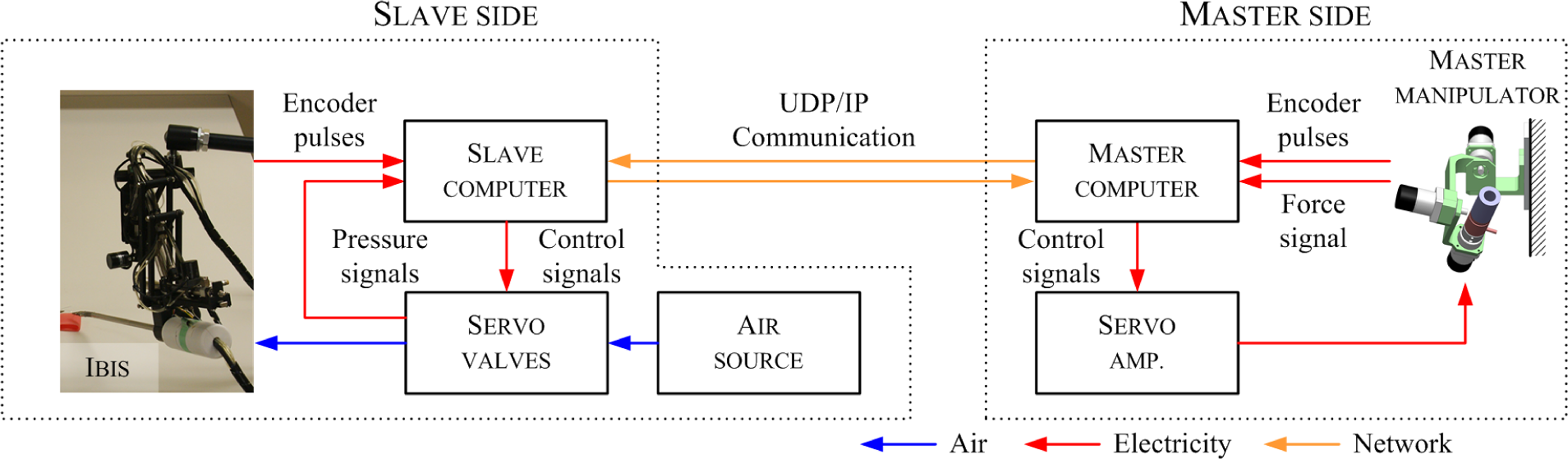
Signal flow in the master–slave system. Red line indicates electricity signal flow, blue line indicates air flow, and yellow line indicates network flow.
Implementation of pseudo HF
Master manipulator with passive HF
Block diagram of the master–lave system is shown in Figure 4. In our previous research, the velocity reference in translation

Block diagrams of the master–slave system.

where
We verified the effectiveness of the system described above in TFLS block transfer tasks by Kim et al. 10 However, this method does not have the ability to transfer the force from the slave to the operator. In addition, the master manipulator has no actuators to display active HF to the operator.
In this work, we propose a control method to drive the pseudo haptic effect. A flexible wrist joint using a spring is used at the tip of the slave forceps to enhance visual effect. At the same time, the velocity reference

For instance, while Ibis is being enforced by an environment, an operator must provide larger force than the external force to the master. Then, the slave manipulator can move against the direction of the external force. Therefore, a pseudo haptic effect can be enhanced not only by the visual feedback but also by the motion restrain.
The control parameters Mm and Bm can be determined in the same manner as equation (2). Since they mostly affect the characteristics of free-space motion (i.e. fest ≈ 0), the values discussed in the study by Kim et al. 10 can be directly applied.
Master–slave system with pseudo HF
On Ibis side, the low-friction-type pneumatic cylinders (CJ2QB10-15; SMC Corporation, Japan) having high back-drivability are used. 12 Wires are connected with the cylinders to drive forces to the tip of the forceps. Since PD controllers are implemented as the position controls of the driving wires, the external force is approximately proportional to the difference between the reference and the actual bending angle ϕ

This helps the operator to visually recognize a contact of an external force. Using both the visual feedback and the motion restrain described at the previous section, the master–slave system is able to display force to the operator as pseudo HF without actuators.
Experiment
HF is helpful in complex surgical tasks, such as knot tying. It is necessary to pull the suture thread with appropriate force. Excessive tension of the thread makes the thread break, and weak tension makes the knot loose.
In this article, through the task of pulling a suture thread using the master–slave system, we evaluated the characteristics of the proposed system with pseudo HF. The performance is evaluated using following two criteria:
Accuracy: The average error of tensional force applied to the suture thread with the manipulator.
Repeatability: The normalized standard deviation of the tension.
Experimental setup
Figure 5 shows the sight of the slave side from the web camera (Logitech CW-900, Logitech Corp., Japan). Silicon tube is placed on the stage. A suture thread (ELP®, 3-0; Akiyama Medical Manufacturing Co., Ltd) is tied on the tube. Left end of the thread is connected to a six-axis force sensor for evaluation of the accuracy of tension. Right end of the thread is gripped by the forceps manipulator. We set the initial position so that the tip of forceps manipulator is perpendicular to the thread, and the flexible joint is not bended.

Overview of experimental setup (slave side).
In this research, to focus on the magnitude of the force, we restricted the DOF of the master–slave system. Therefore, Ibis can be moved only in one direction, left and right.
Figure 6 shows the experimental setup on the master side. Two monitors are used in the experiments. Left monitor is the main screen and right is the sub one. The operator can see the slave side through the main screen. The subscreen displays how strong the operator pull the thread. The keyboard is placed on the armrest, and the operator can press down a key with the left hand.

Overview of experimental setup (master side).
Experiment design
Each trial consists of two sessions as shown in Figure 7. While practice session, the magnitude of the tension f est is displayed on the subscreen. A subject starts to pull the thread toward right until the tension becomes to the reference value. After that, the subject memorizes the magnitude of the tension through the subscreen. The subject returns the tool tip to the initial position.

Experimental procedure. During the practice session, the operator begins to pull the thread using the master–slave system. When the tension becomes to the reference value, |fest| is displayed on the subscreen. During the test session, on the other hand, the tension is not displayed on the subscreen. (a)=Practice session and (b) test session.
During the test session, f est is not displayed on the subscreen. The subject starts to pull the thread recalling the memorized force of the practice session. A key is pushed to record the tension when the subject feels f est as same as the memorized force.
The subject repeats the trial 20 times in each experimental condition. Before the repetition, the subjects trained for more than 5 min in order to familiarize themselves with the master manipulator and the task. The subjects were given breaks of approximately 5 min between each trial.
Seven subjects participated in this experiment. The subjects consisted of men in their 20s. The experiments were executed with the approval of the ethical review in Tokyo Institute of Technology.
Experimental conditions
We evaluated five conditions of the master as follows: without motion restrain but with vision (V), proposed method both vision and motion restrain (kv
= 0.17 N/°: low visual effect; PH), proposed method both vision and motion restrain (kv
= 0.11 N/°: high visual effect; PS), Proposed method (kv
= 0.17 N/°) but without vision (main screen is blind; PN), and with HF using PHANToM Desktop.
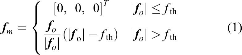
In the condition V, the operator pulls the thread relying on only visual feedback. It is the same condition as f est is not considered in the control method of the master manipulator (using equation (1)). The kv is set to 0.17 N/°. In the condition PH, the operator pulls the thread using master–slave system with pseudo HF. The same kv as the condition V is used. The system provides both vision and motion restrain to the operator. In the condition PS, kv is smaller than that in the condition PH. The kv is set to 0.11 N/°. Therefore, for the same f est, Φ is larger than in PH. The vision effect is higher than PS. In the condition PN, the operator pulls the thread using master–slave system with no vision but only by the motion restrain. kv is same as the conditions V and PH. The experimental conditions are summarized in Table 1. The control parameters used in the experiments are shown in Table 2. The lower limit of the force perception ability is known as 0.3 N or higher. 14 Therefore, the threshold given as 0.35 N in the experiments is reasonable.
Tested experimental conditions.

Control parameters of the master manipulator.

Without the proposed pseudo HF, the operator must pull the thread only relying on visual feedback. The pseudo haptic display is expected to assist the operator to feel the tension and result in more accurate thread pulling. As the maximum tension with hand tying using 2-0 suture thread is almost between 2 N and 3 N, 15 we tested with two tension references, 2 and 3 N, respectively.
Table 2 shows the control parameters of the master manipulator used in the experiment. All parameters were determined by trial and error.
Results and discussion
Figure 8 shows the tracking data for subject A while pulling suture thread. The ranges between black bold lines (0.1 s) are the times when the operator was pressing down the key.

Tracking data while subject A during pulling the thread.
The upper figure shows the results with the condition V. Even the subject can pull the thread properly, the result suggests that the trend of the input force fo was absolutely different from the trend of external force f est.
On the other hand, the second and the third plots show that the trend of the input force fo was similar comparing with f est when the subject pulled the thread using the master manipulator with pseudo HF.
A comparison of the trials and tensions for both 2 N and 3 N is summarized in Figure 9. The averages and normalized standard deviations are calculated for all trials. No learning effect during the experiments can be observed. It is clear that the result of using the master manipulator without pseudo HF is scattered.

Tensions of thread fest in 20 repetitions of the task in the case of subject A. The upper figure is the case that reference tension was set to 2 N. The lower figure is the case that reference tension was set to 3 N. Red: reference force; blue: V; orange: PH; green: PS; black: PN.
Error was defined as follows:

Figure 10 shows the experimental results with the reference force of 2 N. Each bar indicates the mean error as defined in equation (5). The blue, orange, and gray bars indicate the results with condition V, PH, and PN, respectively. F tests are performed in advance to confirm; the variances are the same between the conditions. The asterisk in the figure indicates a pair with a significant difference in T-test (significance level = 5%). The proposed pseudo haptic is clearly effective for four subjects: A, D, E, and G. The difference cannot be seen in subjects B, C, and F. All subjects had low variation when pseudo haptic display was implemented. Same tendency can also be observed with the reference force of 3 N.
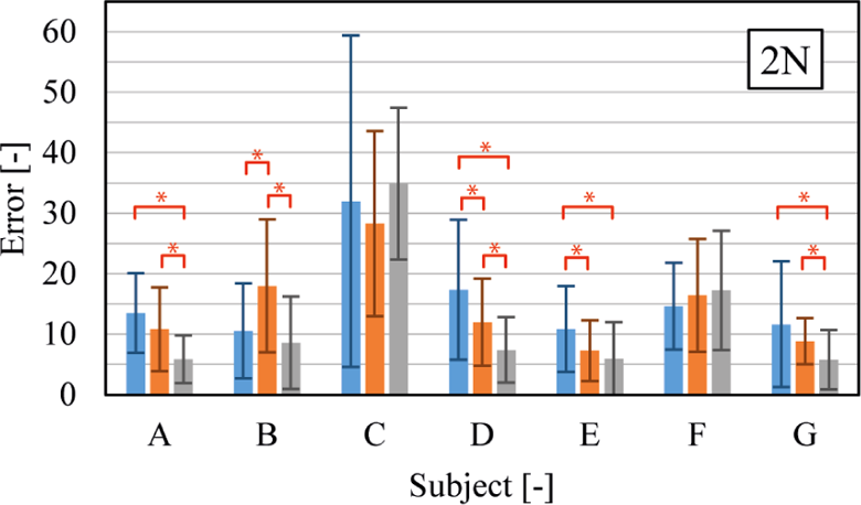
Experimental results. Blue bar: V; orange bar: PH; gray bar: PN. Each bar denotes the mean of errors (%). The asterisk (*) indicates a pair with a significant difference (significance level = 5%) with the T-test.
Figure 11 shows the experimental results to compare the effect of vision. The green, orange, and gray bars indicate the results for the proposed master manipulator with PS, PH, and PN, respectively. As the spring constant is smaller in PS than in PH, the effectiveness of the vision feedback is significant for most of the subjects. However, the vision feedback might become disturbance with PH as the displacement of the spring is slight with the applied force.

Experimental results. Green bar: PS; orange bar: PH; gray bar: PN. Each bar denotes the mean of errors (%). The asterisk (*) indicates a pair with a significant difference (significance level = 5%) with the T-test.
Figure 12 shows the average values of error for whole subjects shown in Figures 11 and 12. The significant difference can be observed in T-test between V and PS. The same tendency is observed with the reference force of 3 N. The effectiveness of the proposed pseudo haptic is demonstrated.
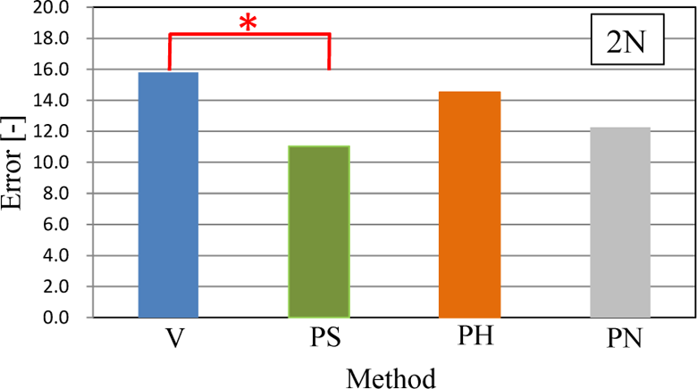
Experimental results. Average values of each method with whole subjects. The asterisk (*) indicates a pair with a significant difference (significance level = 5%) with the T-test.
Figure 13 shows the experimental results compared with the condition of HF (HF with PHANToM Desktop) and PS (proposed pseudo haptics with kv = 0.11 N/°). The experimental results show that no difference can be observed between the methods.

Experimental results. Orange bar: HF; green bar: PS; each bar denotes the mean of errors (%). HF: haptic feedback.
The conventional anisometric master interfaces usually used in the surgical robot have HF but the working range is limited in the translation direction. On the other hand, conventional isometric master interfaces have wide workspace in the translation directions but have no HF. The proposed isometric master device has unlimited work space in the translation directions but also having pseudo HF. This has big advantage especially as a master device of the surgical robot.
The method is introduced to two medical doctors familiar to laparoscopic surgery. They confirmed the method works well for the TFLS task. The method is also acceptable for pulling suture as shown in this article. However, for ligation tasks, they took longer time compared with PHANToM Desktop. We found that the up and down motion with the interface is difficult. The control parameter must be determined individually depended on the translation directions. This will be our future work.
Conclusion
In this article, we have developed a master–slave system with pseudo force feedback. The master manipulator uses the combination of an isometric velocity control technique for translation and an anisometric position control technique for rotation. A pseudo HF method, using both the visual feedback and the motion restrain by generating the velocity command of the robot based on the difference between the master force and slave force, is proposed. The slave manipulator is pneumatically driven and then can estimate the force from the pressure values. The experiments of 1DOF pulling suture threads are conducted and their results show that the subjects were able to pull the suture thread with low variance when the pseudo HF technique was implemented.
One of the conventional master manipulators with HF, PHANToM Desktop, has the best performance, but we confirmed experimentally that the proposed method has the similar performance.
The future work will include as follows: Clarifying the relationship between the angle of flexible joint and pseudo HF accuracy. Determine the suitable control parameters due to the translation directions. Then, challenging complex tasks which contain both precise positioning and force action, such as blood vessel suture, using the proposed system with multi-DOFs.
Footnotes
Declaration of conflicting interests
The author(s) declared no potential conflicts of interest with respect to the research, authorship, and/or publication of this article.
Funding
The author(s) received no financial support for the research, authorship, and/or publication of this article.