
Abstract
This paper presents the steps for the mathematical modelling of a fish robot with four degrees of freedom (DOF) called UC-Ika 1. The swimming motion of the robot, which is inspired by tuna fish, needs to generate an undulatory motion by its tail peduncle and caudal fin. Hence, the robot has the benefit of a tail mechanism that plays a determining role in the dynamic behaviour of the robot. Analysing this tail mechanism and the hydrodynamic forces acting upon the fish robot, the governing equations of motion of the robot are derived. Solving these dynamic equations reveals that the robot has a cruising speed of 0.29 m/s, a slight oscillation in the Y direction, and a small swing around its centre of mass. These results are validated by the experimental results of UC-Ika 1.
Introduction
Undersea operation, oceanic supervision, aquatic life-form observation, pollution search and military detection are just a few examples that demand the development of underwater robots to replace humans [1]. Since the best solutions are always inspired by nature, for the development of an underwater robot, nature's inspiration must be taken into account. Accordingly, a number of bio-inspired robots, such as fish robots, have been developed [2].
A fish robot could be defined as a fish-like aquatic vehicle which is propelled through the undulatory or oscillatory motion of either the body or the fins [3]. The first fish robot, RoboTuna, was built at MIT in 1994 [4]. Three years later, the Vorticity Control Unmanned Undersea Vehicle (VCUUV) was developed based on RoboTuna, with some improvements and additional capabilities, such as obstacle avoidance and the use of up-down motion [5, 6]. Afterwards, a number of institutes and universities developed their own fish robots with further capabilities, such as cruising and turning by use of pectoral fins [7], cruising by use of undulating anal fins [8], and so on.
Robots inspired by various types of fishes could be highly efficient, manoeuvrable and noiseless in a marine environment [3]. For instance, the propulsion systems for some types of fishes achieve up to 90 percent efficiency, while a conventional screw propeller is around 40–50 percent efficient [9].
Nevertheless, existing fish robots exhibit deficiencies regarding their swimming behaviour. Fish robots are developed to have a specific gait of swimming. For instance, some fish robots are developed to swim through the undulation of their tail, while others are able to swim using their pectoral fins. These two kinds of robots give different swimming performances – the former is more suitable for cruising long distances, while the latter is more suitable for hovering and slow swimming. This causes a problem since, e.g., for the navigation of long distances a robot needs to have both of the aforementioned capabilities.
In order to address the aforementioned problem, the authors will to develop a novel fish robot which is able to employ different swimming gaits. As a first step in developing a new fish robot, the swimming behaviour of the robot requires analytical modelling since this is necessary to analyse their swimming behaviour and improve their performance. The modelling of robotic fish is challenging due to the complication of the fluid-structure interaction which can be obtained only through computational fluid dynamics (CFD). Hence, CFD is employed for the modelling of swimming motion in [10, 11, 12]. Although CFD can reliably capture the fluid-structure interaction, this method cannot be employed for control and optimization purposes.
Besides CFD, which is purely a fluid dynamics approach for modelling, the majority of models have a mechanical approach based on the work of Wu [13] and that of Lighthill [14, 15]. Wu [13] modelled a fish as a two-dimensional waving plate. Based on inviscid aerodynamic theory and slender body theory, Lighthill [14, 15] presented the elongated body theory (EBT). Assuming quasi-static conditions, the EBT defines the propulsion of a fish via the sinusoidal wave travelling along the fish body. This method is mainly applicable for anguilliform-like robots whose travelling wave has a constant amplitude from head to tail. Accordingly, Lighthill introduced a large-amplitude elongated body theory which is suitable for the modelling of carangiforms with different body-wave amplitudes [16].
The majority of the existing models of fish swimming rely on Lighthill's work. For instance, Harper et al. [17] proposed a design for tail dynamics with an optimal spring constant for the actuation of an oscillating fin. Similarly, Barrett et al. [18] developed a form of travelling wave using Lighthill's description for the wave as

where ybody is the lateral displacement of the body, x is the body displacement along the main axis, c1 and c2 are linear and quadratic coefficients of wave amplitude envelopes, and k and ω are the body-wave number and frequency. k and ω are defined as k = 2π/λ and ω = 2λf, where λ is the wavelength.
Since (1) is applicable to carangiforms and thunniforms, the mathematical modelling of such fishes is extensively modelled by means of (1), which is also called 'trajectory approximation' [19]. Yu et al. [1] developed a model for a four-link carangiform-like robot using the travelling wave expression. Yu and Wang used their simplified propulsive model for the optimization of the link-length-ratio of their robotic fish [9]. Yan et al. [20] also studied the effects of parameters such as the frequency, amplitude, wavelength, phase difference and coefficient of wave amplitude envelopes on the robot's cruising speed using a travelling wave form of (1). The adoption of the trajectory approximation could be also found in [21].
Trajectory-based models such as [1, 20] use only the experimental observations of the body shape of real fishes during swimming, and apply those observations for the modelling of the body form of the swimming robots. These models are purely kinematics-based models and cannot fully represent the robot's motion, since the roles of propulsive and resistive forces are ignored.
Besides the trajectory approximation method, others have modelled fish swimming taking both the kinematics and dynamics of the robots into account. For instance, McIsaac and Ostrowski [22, 23] have developed a five-link robot using Lagrangian method. In other words, an eel-like robot with an odd number of links is modelled. The simplified hydrodynamic forces of links are adopted from [24]. A multi-body anguilliform robot is also considered by Xu and Niu [25, 26], where the number of links in the system can be even as well. Similar to McIsaac and Ostrowski, Xu and Niu have employed the simplified swimming force model of Ekeberg [24] and the Lagrange method for dynamic analysis.
The trajectory approximation is mainly used for carangiform-like robots and dynamic modelling is applied to anguilliform-like robot locomotion. However, carangiform-like robots are also modelled dynamically, such as in [27 – 33]. The models obtained using both the dynamics and the kinematics of the robots is more reliable, since the essential role of hydrodynamic forces is observed. However, the usage of the current dynamic models is limited due to the following assumptions.
The robots are assumed to be made of a chain of links in series, while the swimming motion of fish robots can be through diverse mechanisms. For example, UC-Ika 1 & 2 are designed and constructed to generate undulatory motion with three links that are not in series. One of the links is directly actuated by the DC motor and the other links are actuated passively. The models are built up with the assumption of a steady or quasi-steady state condition. These two state conditions assume that the flow around the caudal fin has a constant speed. Nevertheless, the speed of the flow is variable and depends upon the swimming behaviour of the fish robot. The existing models consider that the links are in contact with the surrounding fluid and that the hydrodynamic forces are acting directly upon them. This assumption is not reliable since most of the times the robot is covered by a skin layer.
In this paper, a four-DOF fish robot called UC-Ika 1 is modelled. UC-Ika 1, whose name originates from a Maori word for fish (ika), is inspired from a tuna. The tuna fish belongs to the thunniforms category of fish swimming modes [34]. The model has four DOF that represent the dynamic behaviour of the robot in a cruising gait of swimming resembling a tuna. The model adopts the modified hydrodynamic force model of [35]. Most of the existing mathematical models have considered the fluid inertia as an added mass to the mass of the fish, appearing in the left-hand side of the dynamic equations of motion. In this model, the fluid inertia force is directly employed as a force in the right-hand side of the equation. This simplifies the derivation of the equations. The hydrodynamic forces are then calculated considering those DOF and the variable speed of the flow around the fish. This variability submits a more representative model, although it is vulnerable due to the constant parameters of the equations, including the frequency and amplitude of the undulation wave.
The rest of the paper comprises five sections. The n ext section introduces the mechanical design and swimming modes of fishes. In Section 3, the tail mechanism of the robot as the fish propeller is analysed. In Section 4, the kinematics of the robot are the focus of attention. Section 5 introduces the hydrodynamic forces acting upon the fish. Dynamic equations of motion are presented in Section 6. These are followed by the results in Section 7, which are discussed and compared to the performance of UC-Ika 1. Finally, the paper is concluded.
The main factor which distinguishes fish robots from other types of underwater vehicles is their propulsion system. Fish robots generally employ either undulatory or oscillatory swimming. When a fish passes a travelling wave along its body or its fins, the swimming method is referred to as 'undulatory'. On the other hand, in oscillatory mode the fish generates propulsion by oscillating a certain part of its body around its base [36]. The robot discussed in the paper propels itself using an undulatory tail.
As Figure 1 illustrates, UC-Ika 1 includes a main body, a tail peduncle, pectoral fins and a caudal fin. The main body is rigid and contains all the electronics, including a microcontroller, batteries, sensors and a DC motor. The pectoral fins are fixed to the main body and do not have any motion. The tail is flexible, since a carangiform-like robot undulates from their tail [34]. The actuation mechanism of the tail-except the DC motor – is inside the tail. The actuation mechanism is described in detail in the following sections. The crescent-shaped caudal fin is connected to the tail using a rubber. The rubber is then modelled with an angular spring and damper. The caudal fin contributes to the propulsion the most.

CAD design of the fabricated fish robot
The fish robot is designed and fabricated to investigate the swimming performance of a tuna-mimetic robot during cruising motion. To do so, the undulation of the tail and the caudal fin are symmetrical so as to cancel out the lateral forces and propel the fish robot forward. In addition, since cruising is one type of planar motion, UC-Ika 1 excludes any mechanism that could take the fish upwards or downwards in the water, such as a buoyancy control system, the inclination of the tail or rotation of the pectoral fins.
The undulatory motion of the tail of tuna fish plays a significant role in their efficient cruising. Accordingly, the tail mechanism of tuna-mimetic robots like UC-Ika 1 needs to generate this undulatory motion – and frequently – using a number of links that are connected together in series [37, 38]. However, UC-Ika 1 has the benefit of a tail mechanism, as shown in Figure 2, which is more complicated than similar tuna-mimetic robots.

Link mechanism of the tail peduncle
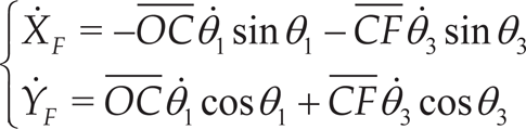
The tail peduncle of UC-Ika 1 consists of three links. All three links are actuated by a single DC motor connected to Link 1. In other words, once the motor is activated to provide oscillatory motion for Link 1, the other two links also start moving. Through kinematical analysis, the relationship between the links of the tail mechanism with respect to the relative reference frame placed at point O is provided with the following expressions.


Solving the previous expressions, four unknown parameters,

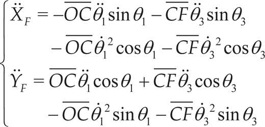
The derivatives of expressions 2, 3, 4 and 5 determine θ
Similarly, the angular acceleration of the links,
Knowing the behaviour of point F with respect to the relative reference frame, the swimming performance of the robot is analysed with regard to the absolute reference frame. To do this, a schematic sketch of the fish robot is provided in Figure 3.

A schematic sketch of UC-Ika 1
Considering Figure 2, the position of point G is expressed by


where θ1 is the actuation angle provided by means of the DC motor as
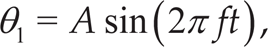
where A, f and t are the amplitude, frequency and time, in turn. θ3 also depends upon θ1 by a constant using the following expression as

λ depends upon the sizes of the links of the tail mechanism, including
X, Y, Φ and θ4 in the previous expressions are the DOF the model, namely translations in the X and Y directions, the rotation around the centre of mass of the robot, Φ, and the rotation of the caudal fin, θ4.
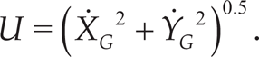
Note that the resultant velocity of point G, defined as U, is expressed by
The hydrodynamic forces are considered based on the following assumptions:
The main body rotation is negligible. Only the caudal fin is responsible for propulsion. The fluid around the fish robot is inviscid.
Taking these assumptions into account, the main hydrodynamic forces acting upon the fish robot are shown in Figure 4.

The free-body diagram of the forces acting upon UC-Ika 1
In general, two main hydrodynamic forces can act on the fins, namely lift and drag forces. However, lift forces are not considered here since the main body is symmetric relative to the X−Z plane and its rotation is neglected. The drag force of the main body are thus[32]


where Sx and Sy are the fish robot's projected area, and CDx and CDy are the drag coefficients of the fish robot along the X and Y directions, respectively. In addition, CDy is the yaw drag coefficient, ρ is the water density, L0 is the distance between the centre of mass of the robot, point M and L1 are the distance between point M and point F.
A number of hydrodynamic models for fish swimming have been presented, such as waving plate theory [13]. However, the most suitable model for carangiform-like robots with small lateral motion of the tail is elongated body theory, introduced by Lighthill [14]. Based on Lighthill's theory, Nakashima et al. [35] have described the lift and fluid inertial forces by

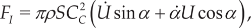
where S and 2Cc are the span and the chord of the caudal fin, respectively, and α is the instantaneous angle of attack defined by the following expression

Figure 5 depicts the free-body diagram of the inertial and lift forces acting upon the caudal fin.

The free-body diagram of the forces acting upon the caudal fin
With (17) and (18), FCx and FCy are obtained as


where FCx and FCy are the thrust and the lateral force generated by the fish robot during swimming.
It has been previously mentioned that the robot has four DOF, including X, Y, Φ and θ4, while the input to the system is the motor torque, T. However, T cannot directly affect the swimming behaviour of the robot, since increasing torque only increases the oscillation frequency of Link 1, f. The oscillation amplitude of Link 1, A, is constrained kinematically by the tail mechanism. While A is a constant parameter, f needs to be determined by

Expression (22) is the relationship between the torque and speed of a typical DC motor used in the fish robot shown in Figure 6.

The relationship between the frequency and torque of the motor
Substituting A and f into expression (11), θ1 is employed as the input to the dynamic model of the robot.
Considering the DOF, four equations of motion are derived as:


Substituting the hydrodynamic forces into the equations (23–26) yields a coupled nonlinear system of the fluid mechanics structure. Accordingly, the system is solved by a numerical method called the 'Runge-Kutta Fehlberg' method.
The hydrodynamic forces generated by the motion of the caudal fin determine the swimming performance of the fish robot. However, those forces are significantly affected by the dynamic behaviour of point F, which is actuated by Link 1 of the tail mechanism.
Considering Figure 2, in order to analyse the motion of point F, the angular displacement, velocity and acceleration of Link 1 and Link 3 should be computed. By substituting the sizes of the links given in Table 1 into expressions 2, 3, 4 and 5, θ3 is obtained. The following Figure depicts θ1 and θ3 during two complete cycles.
Known parameters

Known parameters
Considering Figure 7, the amplitudes of θ1 and θ3 are 7.5 deg and 16.177 deg, respectively. Thus, by using expression (12), λ is achieved to be equal to 2.146.

Angular motion of Link 1 and Link 3
Similar to the angular displacement, the angular velocity and acceleration of Links 1 and 3 are calculated, whose amplitudes are
The displacement, velocity and acceleration of point F with respect to the relative reference frame are obtained using

Displacement of point F
Once the tail mechanism behaviour is analysed, the swimming performance of the robot can be observed. The analysis of the tail mechanism submits the value of λ. Substituting λ and the constant parameters given in Table 2 into the equations of motion, (23–26), reveals the capabilities of the robot in planar motion. It also illustrates how the caudal fin behaves during swimming.
Parameters

While the model verifies that the robot swims forward along X, as illustrated in Figure 9, it also shows the slight periodic motion of the robot in the Y direction. In other words, the robot has lateral periodic motion with an amplitude of 0.025 m (see Figure 10).

Translational motion of the fish robot along the X axis
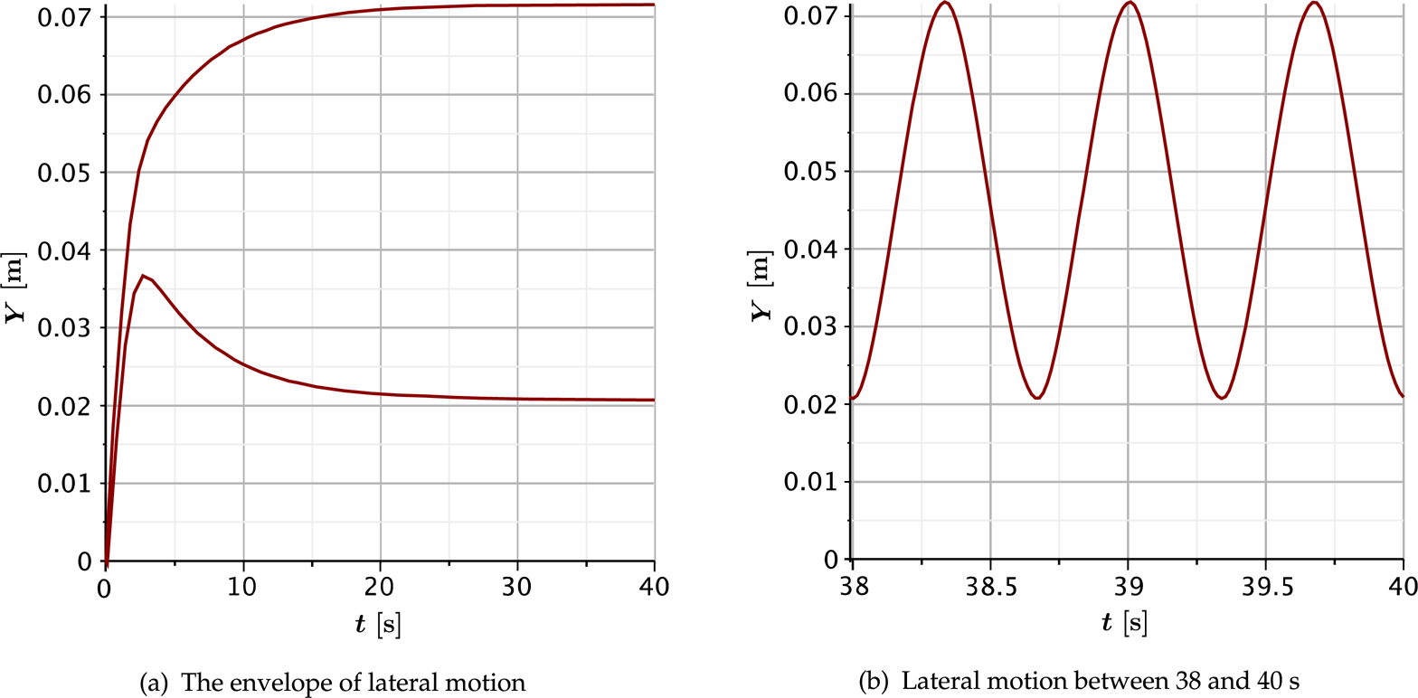
Translational motion of the fish robot along the Y axis
The robot has a transient motion for 30 s to reach an average cruising speed of 0.29 m/s (see Figure 11).
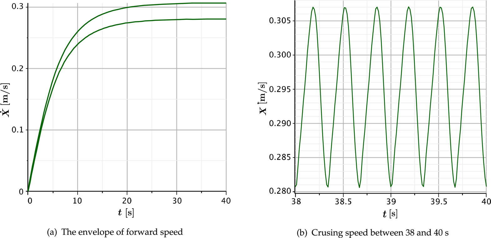
Speed of the fish robot along the X axis
As expected from the lateral periodic motion of the robot, the model of UC-Ika 1 shows that it experiences a periodic speed laterally (see Figure 12).

Speed of the fish robot along the Y axis
The model also indicates that the robot swings around its centre of mass with a maximum rotation of 5.56 degrees from its cruising axis (see Figure 13).

The fish swinging around its centre of mass
In addition to the above results, Figure 14 illustrates that the caudal fin has a periodic motion with an amplitude 18.7 degrees.

Caudal fin rotation around point F
The results explained in the previous paragraphs are validated by experimental testing of the fish robot. The fish robot of the mathematical model shown in Figure 15 is tested in a water tank. The test proved that the robot has a cruising speed of 0.29 m/s. A slight translational motion of the robot along the Y axis is also detected; it also swings slightly around its center of mass with an amplitude of 5.56 degrees.

UC-Ika 1, the first fish robot developed at the University of Canterbury
In this paper, a fish robot called UC-Ika 1 is mathematically modelled. UC-Ika 1 has four DOF: translations in the X and Y directions, the rotation around the centre of mass of the robot, Φ, and the rotation of the caudal fin around its joint to the tail peduncle, θ4. The robot swims by the undulatory motion of its body and its caudal fin. The undulatory motion is generated by the tail mechanism, which is actuated by a single DC motor.
As the first step of modelling the tail mechanism is kinematically analysed with respect to the relative reference frame. Next, the swimming behaviour of the robot with respect to the absolute reference frame is investigated. This swimming behaviour is associated with the hydrodynamic forces that act upon the fish robot. Finally, the governing equations of motion of the robot are derived. Substituting the hydrodynamic forces into the equations of motion yields the coupled nonlinear system, which is solved using the Rung-Kutta Fehlberg method.
The mathematical model shows the gradual increase in the lateral motion of the tail towards the end of the tail. The rotation of Link 3 is 2.176 times of that of Link 1. This provides the undulatory motion required for tuna-like robots. The model also reveals a cruising speed of 0.29 m/s, which is validated with the experimental test of UC-Ika 1. In addition, a slight translational motion of the robot is detected in both the simulation and the experiment. The robot also exhibits a slight swing around its centre of mass, with an amplitude of 5.56 deg as confirmed by experiment.
In future work, the swimming behaviour of the robot will be further investigated in order to improve its performance. The dynamics system of the robot motion will be optimized based on the swimming efficiency of the robot. Using the optimization results, a new fish robot will be fabricated to compare its performance, in both experiments and simulations, with the performance of UC-Ika 1.