
Abstract
In this paper, a novel design of a biomimetic robot fish is presented. Based on the propulsion and maneuvering mechanisms of real fishes, a tail mechanical structure with cams and connecting rods for fitting carangiform fish body wave is designed, which provides the main propulsion. Two pectoral fins are mounted, and each pectoral fin can flap separately and rotate freely. Coordinating the movements of the tail and pectoral fins, the robot fish can simulate the movements of fishes in water. In order to obtain the necessary environmental information, several kinds of sensors (video, infrared, temperature, pressure and PH value sensors) were mounted. Finally, the realization of the robot fish is presented.
Introduction
For many years human beings have been impressed by the incredible swimming ability of the fish, and much attention has been paid on the high efficiency and maneuverability of its propulsion and maneuvering mechanism. These characteristics of real fishes are far better than ships and submarines, which attract robotics researchers greatly in recent years. Developing a biomimetic robot fish with high velocity, high efficiency and high maneuverability has been a hotspot.
Many research works have been done on the propulsive theory. Lighthill build a model based on elongated-body theory to analyze the carangiform propulsive mechanism (Lighthill, 1960,1970), and the large-amplitude elongated-body theory (Lighthill, 1971) was propounded to analyze the irregularly amplitude of tail. Wu has developed a two-dimensional (2-D) waving plate theory, treating fishes as an elastic plate (Wu, 1961). Triantfyllou et al. (1995, 1996) has founded that the jet formed behind the fish body plays an important part as propulsion. Tong has developed the 3-D waving plate theory (3DWDP) based on the 2-D waving plate theory and a semi-analytic semi-numeric method is adopted to solve the 3-D nonstationary linear solutions (Tong, 2000).
The theoretical and experimental studies have explored the possibility of applying the propulsive mechanism of fishes for aquatic vehicles. MIT has successfully developed an eight-link, fish-like machine—RoboTuna, which may be the first free-swimming robotic fish in the world. RoboTuna and subsequent RoboPike (Triantafyllou et al. 1995) and (Barrett et al. 1999) projects attempted to create AUVs with increased energy savings and longer mission duration by utilizing a flexible posterior body and a flapping foil (tail fin) that exploited external fluid forces to produce thrust. Marine Science Center of Northeastern University has developed an undulatory system that was based on the lamprey, which utilized the SMA (Shape Memory Alloy). It may control the depth by the lateral body wave. Kato has considered the control of pectoral fins-like mechanical structure as a propulsor and built a Blackbass Robot prototype (Kato N, et al. 1996). In Nagoya University, Fukuda has developed a fish-like micro robot prototype which possesses a pair of fins actuated by piezoceramics (T Fukuda, et al. 1994).
Also, the domestic research institutions have done a large amount of work in robot fish research. The Robotics Institute of Beijing University of Aeronautics and Astronautics has designed a biomimetic robot-eel prototype and a robot dolphin with which some experiments are made to study the mechanism of propulsion (Liang, et al. 2004). The Harbin Engineering University has developed an octopus-imitating robot (Peng, et al. 2004). The Harbin Institute of Technology has conducted underwater robot research on imitating the propulsion mechanical structure of fish fins and constructed an experiment platform using elastic module (Liu, et al. 2000). Shenyang Institute of Automation Chinese Academy of Sciences has developed a two-link biomimetic robot fish prototype. Institute of Automation Chinese Academy of Sciences has studied on the control and coordination of robot fish.
The present biomimetic robot fish are usually fish-like machines motivated by BCF (Body and/or Caudal Fin), which imitate the locomotion of fish by controlling the position of several independence joints (Yu, et al. 2005) and (Zhou, et al. 2006). The control law is a bit complex because the joints need fit the fish body wave curve. In this paper, we endeavor to explore the new implement manner of robot fish. A mechanical structure with cams and connecting rods is designed to fit real fish's body wave curve and thus the robot fish may swim freely without complex motor control law. In addition, an original three-fin structure (TFS) that is composed of a tail fin and two pectoral fins with 3-DOF (Degrees of Freedom) is introduced to provide more flexibility adaptability with robot fish. Several kinds of sensors are mounted and the related information processing methods are given to endow the robot fish with certain autonomy. A new means for underwater environment observation based on robot fish is provided and it may recognize goals actively.
The rest of the paper is organized as follows. The analysis of the carangiform propulsive wave curve and the design of tail mechanical structure are introduced in Section II. Section III describes the design of pectoral fins. The control architecture is presented in Section IV. The realization of the robot fish and the experiment are introduced in Section V and Section VI concludes the paper.
Design of the Tail Mechanical Structure
The researchers on the fish behaviors point out that there is traveling wave, which travels from the neck to the tail implicit in the body of swimming fish. The wave appears as the curvature of the spine and muscle, gradually increasing amplitude, and it travels faster than forward movement. The carangiform propulsive wave curve starts from the fish's center of inertia to the caudal joint, which is assumed to take the form of (1) (Yu, et al. 2005)

where y body is the transverse displacement of body, x is the displacement along main axis, k is the body wave number (k = 2π/Λ), Λ is the body wave length, c1 is the linear wave amplitude envelope, c2 is the quadratic wave amplitude envelope, Ω is the body wave frequency (ω=2πf=2π/T). A sample of the fish body wave curve is shown in Fig. 1.
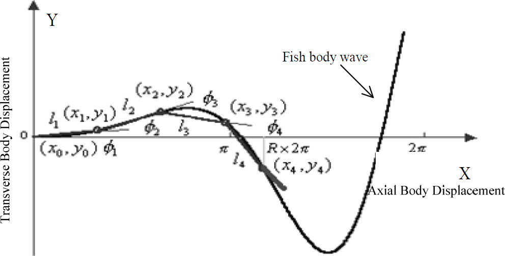
Fish body wave curve
Once the proper body wave constants are determined under some constraint conditions, the curve is obtained. To control the biomimetic robot fish conveniently, discrete (1) by discreting t with i and we get the curves of fish body in each sampling cycle. Then substituting x, y
body
with x
i,j
and y
i,j
respectively, we have (Yu, et al. 2005),

where i is the variable of spline curve sequence, M is the body-wave resolution that represents the discrete degree of the overall traveling wave, which is restricted by the maximum oscillation frequency of motors.
The tail parameters of the biomimetic robot fish include the tail fin shape S, relative wavelength R, number of joints N, length of joints L j (j=1,2…N), and the position of every joint end P={(x j ,y j )}, (i=1,2…M; j=1,2…N) in every sampling cycle.
The tail fin shape S: The tail fin shape is closely related to the characteristic of swimming body. Because the propulsive power is mainly provided by the tail in carangiform mode, a crescent-shaped fin made of the rigid material with a thin caudal peduncle is chosen according to the model.
Relative wavelength R: We define relative wavelength as the length ratio of wavelength exhibited by the fish's oscillatory part to that of a whole sine wave. The reduction of R results in the increase of propulsive efficiency, the increase of velocity, and the reduction of maneuverability (Yu, et al. 2005). We refer to carangiform mode and let R≈1/3.
Number of joints N: Joints are designed to fit the tail oscillating characteristic for performing the biomimetic motion. The j th joint is between (x j-1 ,y j-1 ) and (x j ,y j ), as shown in Fig.1. The increase of N results in the increase of the flexibility of fish body, the reduction of error of curvefitting, and the increase of maneuverability. Considering too many joints making it difficult to build a steady structure of the electromechanical system and the increasing accumulation errors, N is chosen 2 in this paper. The length of joints L j and position of every joint end P: the oscillatory tail is composed of N joints. The length of every joint is decided by the features of fish body wave. From Eq.(2), it is seen that the wave amplitude increases gradually from the beginning part to the end, and reaches the max at the caudal peduncle. Thus the length of joints reduces gradually, and the flexibility is larger with the shorter joint. Considering the structure and motors, the shorter the joint is, the bigger the torque it can offer is, the higher the oscillatory tail frequency is. In practice, L1 : L2 = 1 : 0.5.
The problem to be solved is to find appropriate length of the joints L j , which makes the joint end to end on the fish body wave curve, and the abscissa of the last joint endpoint is Rx2π, which is shown in Fig.1.
The coordinates of the j
th
joint fits Eq.(1), we have

And it must satisfy the constraint condition given by

To solve the set of equations composed by Eq.(3) and Eq.(4), an iterated algorithm is given in the following.
Let L j = p j L1 (j>1), where p j is the chosen scale of joints.
Construct the error function as follows:

By iterating L1, we firstly calculate (x i,j ,y i,j ) (j=1,2…N) in turn with initial condition xi,0 = yi,0 = 0. If e 1 obtained by Eq.(5) is small enough, L 1 and (x i,j ,y i,j ) (j=1,2…N) can be gained, then all the lengths of joints are acquired, or else, let L 1 = L 1 +step 1 , recalculate until e 1 is very small.
The process to solve (x
i,j
,y
i,j
) is given in the following.


When the j th joint is calculated, we iterate x i,j = x i,j−1 + m × step 2 with known (xi,j−1,yi,j−1). (x' i,j ,y‘ i,j ) is obtained from Eq.(3) and calculate e2. Repeat these steps until e2 is small enough, (x i,j , y i,j ) is calculated in turn.
A platform FBW S(Fish's Body-Wave Simulation) is built to simulate the locomotion of the robot fish base on the algorithm mentioned above, the characteristics of the configuration and motions of fish, which makes it easy to calculate and simulate. This simulation platform provides the visualization of the motions with the constraint of mechanical structure and the performance, which is important to the structure design and motion control. The platform is shown in Fig. 2. Fig.2(a) gives the parameters calculation and Fig. 2(b) shows all joints fitting curves in a whole period of the tail oscillating and every curve depicts the positions of all tail joints at a moment. The parameters of all joints may be obtained conveniently according to the platform.

The simulation platform of the robot fish locomotion
The schematic diagram of the tail mechanical structure is shown in Fig. 3. The tail mechanical structure is composed of two parts: Oscillate part and Drive part. The Oscillate part simulates the fish tail motion by two joints designed according to the tail parameters calculated above. The Drive part of the tail is composed of a pair of cams and two slide bars S i (i = 1, 2) connected to joints.

The tail mechanical structure
These two cams rotate in reverse directions to push slide bars in the direction of body-axis to drive all joints and the tail fin to oscillate. By calculating the appropriate cam shape, we may implement the position control of slide bars at all the sampling points, which may drive the tail to fit the carangiform propulsive mechanism. DC motors are adopted in this paper instead of step motors or servo actuators, which may offer more propulsion power.
The design method of the cams is given as follows: firstly, the coordinate of the end of j
th
joint (x
i,j
,y
i,j
) at i is obtained based on the above simulation platform. Then we calculate the angle γ
i,j
between the joints and the x-axis (axial body), which is given by

According to γ i,j , the traveling distances xi,1 and xi,2 of slide bars at all the sampling points are calculated. By kinematic inversion based on the xi,1 and xi,2, the cam shape and its size are acquired with appropriate pressure angle.
The structure can convert the rotation of motor into the oscillation of the tail to fit the fish body wave. The motor control signal is linear instead of complex control law that is generated to fit fish body wave, which is easy to control.
The robot fish tail may perform the motions, i.e. acceleration, deceleration and uniform motion, by different signals sent to the motor of the robot fish tail.
Acceleration: The increase of duty ratio of the PWM signal to control the tail motor results in the increase of the tail's oscillatory frequency, which increases the speed. Deceleration: Contrary to acceleration, the reduction of duty ratio of the PWM signal may result in the deceleration of the speed.
Uniform motion: The tail motor rotates uniformly, and the pectoral fins steady to the horizontal position.
Fishes swim and keep balance by using fins. The balance is mainly controlled by pectoral fins and they may also control the posture. The locomotion of the fish pectoral fins can be simplified to two kinds of fundamental motions: rotation and flap. Influenced by the characteristics of the fishes, the designed robot fish is equipped with a pair of pectoral fins, each of which can flap separately and rotate freely, as shown in Fig. 4. In order to simplify the mechanical structure and control, the rotation motions of two pectoral fins may be uniform, thus there are three degrees of freedom in total and each is corresponding to a motor. When the motor 2 rotates, both pectoral fins roll synchronously to change the attack angle. The motor 1 and motor 3 rotate forward and backward in a certain angle range to make the left/right pectoral fin flap continuously. This structure satisfies the maneuverability of the locomotion.

The pectoral fins structure
The locomotion of the fish fins is the typical rhythmic movement. The fish adjusts its posture in water by controlling the oscillatory frequency and the attack angle of the tail and pectoral fins. Generally speaking, the locomotion of the fish related to the pectoral fins can be grouped into several types i.e. crash stop; back off; turn (left and right); pitch (submergence and ascent); roll (clockwise and counterclockwise). The robot fish can choose different combination of these motions according to the tasks executed in water.
Crash stop: the pectoral fins steady vertically while the tail stops oscillating. The velocity of the robot fish reduces quickly because of the resistance of water.
Back off: the pectoral fins act as the following sequence (see Fig. 5) and the tail stops oscillating.

The motion sequence for back off motion
Turn: The robot fish turns right/left by flapping the left/right pectoral fin. The flapping frequency is decided by the turning radius required: the higher the frequency is, the smaller the turning radius is.
Pitch: The robot fish may submerge or ascend during the swimming by adjusting the rotation angle of pectoral fins. When the pectoral fins rotate clockwise to a specific angle, the robot fish ascends to the surface because of the water pressure. Similarly, the fish submerges when the pectoral fins rotate counterclockwise to the submerge-angle.
Roll: The robot fish rolls clockwise when the right pectoral fin moves downward with the left one upward, and then these two fins flap at the same time. It rolls counterclockwise with right fin upward and left fin downward.
The control system is depicted in Fig. 6. MCU sends PWM signal to the motor driver to control the tail motor's speed, and thus the oscillatory frequency of the tail is controlled by the duty ratio of the PWM signal. CPLD (Complex Programmable Logic Device) controls the servo actuators of pectoral fins system by PWM signal, whose duty ratio is decided by MCU, and thus the pectoral fins perform the proper motion. The MCU may communicate with the upper console by the wireless module.
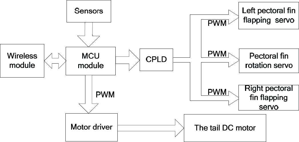
The block diagram of the control system
When the robot fish performs a task in complex underwater environments, it needs to perceive the environment. For this purpose, multiple sensors are equipped with the robot fish to gather environmental information, i.e. water depth, neighboring obstacles. According to the characteristics of sensors, pressure sensors, a CCD camera, a temperature transducer, infrared sensors and a PH value sensor are chosen.
The biomimetic robot fish may make decisions intelligently based on the sensors information to a certain degree. Avoiding obstacles is one of the premises of swimming safely. In the sensors system of the robot fish, the infrared sensors are used to detect nearby obstacles. As described above, there are three infrared sensors mounted on right (SIR), middle (SIM), left (SIS) side of the fish head. The robot fish may make decisions based on the states of sensors. The logic rules set is given in Table I, which gives the relationships between motions of robot fish and states of sensors, and it is performed by the MCU module of the robot fish.
The Logic Rules Set

The CCD camera is mounted on the head of the robot fish and it provides video information to upper console by wireless in high frequency for displaying and processing. The upper console receives the video signal by a video capture card and then extracts the valid information based on a threshold-adjusting image segmentation algorithm (Shen, et al. 2006). The schematic of signal transmitting system is given in Fig. 7. The water depth information can be gained by pressure sensors and thus the robot fish can control its diving depth. In order to acquire the water temperature, a temperature transducer is adopted. The robot fish may analyze the variation rule of environmental temperature. In addition, we adopt the PH value sensor to detect the polluted waters. The robot fish searches the waters and sends back the PH value for analyzing the alkalinity acidity of the waters, which is useful to the environment protection.
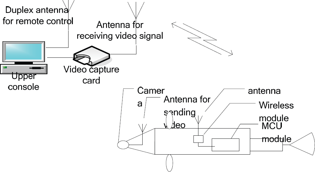
The schematic of signal transmitting system
Based on the sensors chosen, the system architecture of the robot fish is proposed, which is shown in Fig. 8. The sensors information may be sent to the upper console by wireless and the operator may send wireless instructions to control the robot by observing the related information. The robot fish may make decisions intelligently based on the sensors information in some cases or execute the task by combining the commands from the upper console.

The control architecture of the robot fish
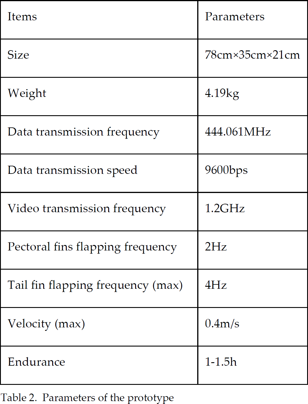
Fig. 9 gives a functional prototype of the biomimetic robot fish with a tail for propulsion, three freedom degree pectoral fins, and multiple sensors. The parameters of the prototype are shown in Table 2. The prototype is made up of 5 parts:
Parameters of the prototype
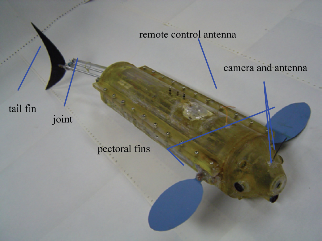
The prototype of the biomimetic robot fish
The sensors system: includes all kinds of sensors described in Section IV with well-arranged layout and the corresponding processing circuits.
The control system: includes MCU circuit, wireless modem, the power supply, the control and drive module of motors.
The tail structure: includes a DC motor, a tail fin, the cams and joints system designed in Section II.
The pectoral fins system: includes three servo actuators, the transmission gear, and pectoral fins.
The vision system: includes the CCD camera, the wireless transmission system, and the power supply.
Fig. 10(a)–(f) show a motion sequence of the biomimetic robot fish swimming in the experiment pool. Another experiment is related to goal recognition. The camera on fish sends out the video. The upper console extracts the goal based on the given color decided by the operator. Fig. 11 (a) gives the selected images from the CCD camera of the robot fish, where the robot fish swims in the blue experiment pool with a yellow obstacle A and the red ball B that is the goal to be recognized. The corresponding recognition result in the upper console is shown in Fig. 11 (b), which shows that the goal is successfully recognized, which is very useful for future process.
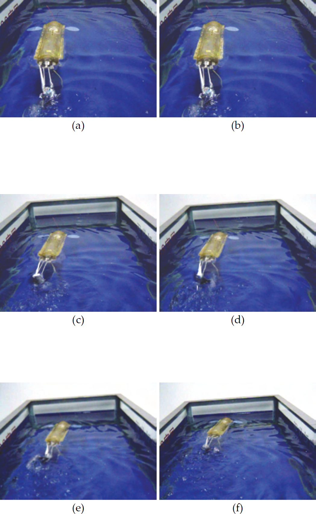
The robot fish swimming in the water

The selected image and the corresponding recognition result
In this paper, a novel biomimetic robot fish with a tail for propulsion, three freedom degrees pectoral fins, and multiple sensors is designed based on the analysis of propulsion and maneuvering mechanisms for carangiform swimming.
The deliberate design of original three-fin mechanical structure, control of three fins' coordination and the sensors system guarantees the robot fish can simulate the movements of the real fish. The robot fish can communicate with the upper console by wireless communication, and it can execute a series of suitable actions or behaviors according to the decisions made by itself and the instructions received from the operator. Some experiments are carried out upon the robot fish with the new mechanical structure and control system, and the results have demonstrated the good performance of the novel mechanical structure and control system of the biomimetic robot fish.
Footnotes
7.
This work is funded by research grants from NSFC (No. 50475179, 60635010, 60605026), CASIA Innovation Fund for Young Scientists, and 863 Project (No. 2006AA11Z225, 2006AA04Z258).