
Abstract
Bio-inspired robotic fish hold strong promise for underwater missions. This paper deals with the design and control issues of a miniature free-swimming robotic fish with multiple sensors. Specifically, a synthesized mechanical design scheme mainly relying on a two-link serial mechanism and a pair of mechanical pectoral fins is first presented. Next, a bio-inspired Central Pattern Generator (CPG) based control method aided by feedback information from multiple sensors of various types to achieve three-dimensional swimming is proposed. Finally, experimental results on the 35-centimetre-long robotic fish verify the efficacy of the proposed mechatronic design and control methods. It is found that the CPG control combined with sensory information greatly contributes to swimming ability and intelligence of the robotic fish.
1. Introduction
With the advancement of fast-moving robot technologies, there has been a rapid growth of interest worldwide in underwater exploration, due to its rich marine resources and element of the unknown. In particular, underwater vehicles are becoming more common in a variety of real-world applications, such as underwater exploration, search and recovery, as well as military purposes. As demands for energy-efficient, highly manoeuvrable and stealthy autonomous underwater vehicles are rapidly increasing, researchers have turned to nature for a great variety of design inspirations [1–3]. Fortunately, real fish offer design and control paradigms or solutions. To date, fish-inspired swimming robots (hereafter termed robotic fish) have shown superior performance in efficient propulsion and high manoeuvrability compared with conventional underwater vehicles propelled by rotary propellers [4–10].
As a specific underwater vehicle platform, robotic fish are ready for a number of potential applications in a cooperative or non-cooperative manner, such as underwater exploration, archaeology, patrol, aquatic monitoring and mobile sensing, which are difficult or expensive for traditional autonomous underwater vehicles. On the other hand, robotic fish have an advantage over biological fish by allowing programmable motions that permit investigation of discrete components of naturally coupled movements. The existing studies have been almost exclusively focused on the theoretical aspects and development of large robotic fishes with body length of up to 50 cm or longer. Among those with the propulsive mechanism of multi-linkage, the number of active joints is three or more. There have been few or limited studies on robotic fish with only one or two joints. In reality, a miniature, intelligent robotic fish will play an important role in underwater exploration, especially in cave searching, due to its limited size. The predominant challenge is how to achieve diverse fish-like motions such as forward swimming, turning, diving and surfacing via the propulsive configuration of two links.
In this paper, the aim is to design and implement a miniature, two-link, free-swimming robotic fish with multiple types of sensors, on the basis of our previous work on fish-like swimming [11, 12]. More specifically, a 35-centimetre-long robotic fish with two tail joints and a pair of mechanical pectoral fins is designed to validate the functionality of the two-link mechanism. In the meantime, by using the feedback information from various sensors, this study proposes a high-level control to regulate parameters in central pattern generators (CPGs) in order to regulate the three-dimensional (3D) movements of the robotic fish. Finally, aquatic tests on the actual robot verify the effectiveness of the proposed mechanism and control methods.
The remainder of the paper is organized as follows: the overall mechatronic design of the miniature robotic fish with multiple sensors is overviewed in Section 2. The motion control method combining the CPG controller and feedback from sensors is detailed in Section 3. Experimental results are described in Section 4. Finally, Section 5 concludes the paper with an outline of future work.
2. Design of the Miniature Robotic Fish
This section gives a brief overview of the developed miniature free-swimming robotic fish and the system framework used for real-time fish-like swimming.
2.1. Mechatronic design
Figure 1 shows a schematic of the developed miniature robotic fish modelled on a shark. The main reason for mimicry of a shark body is that the shark body can afford plenty of space for housing mechatronic parts. As can be seen, the 35-centimetre-long robotic fish has multiple fins including a heterocercal caudal fin and a pair of pectoral fins. Mechanically, the robotic fish consists of a rigid head housing multiple sensors, control circuits, a lithium battery pack, a flexible body with two active joints and a caudal fin. Each joint is actuated by one servo motor, whose control signal is produced by the fine-tuned CPG controller. Coordinated multiple joints allow the robot to swim forwards/backwards, submerge, surface and turn. Specifically, the body and caudal fin (BCF) mode is applied to the robotic fish propulsion and manoeuvring [13]. The detailed technical specifications of the miniature robotic fish are tabulated in Table 1.

Mechanical configuration of the miniature robotic fish
Technical specifications of the miniature robotic fish

Due to the limited size of the miniature robotic fish, there is not enough free space to hold two servo motors to drive each pectoral fin. Thus, a servo motor along with a pair of gears is adopted. As shown in Figure 2, the servo motor drives the two pectoral fins through the pair of gears. They will be rotated to the same angular position simultaneously.
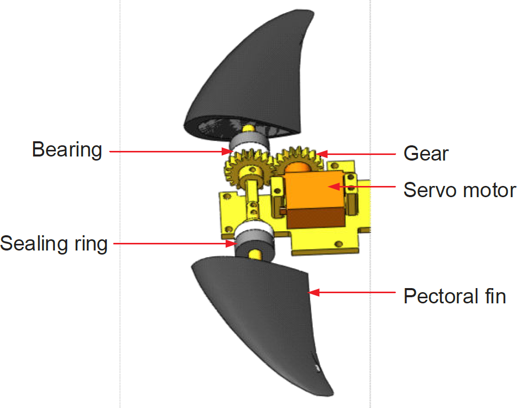
Mechanical design of the mechanical pectoral fin
2.2. Control system framework
To control multiple fins and guide the robotic fish to the desired destination, we propose a hybrid embedded control system framework. The robotic fish can work in both remote control mode and automatic mode. As illustrated in Figure 3, a PC is used as the host, which is responsible for remote control and monitor of the robotic fish. At the client level, a hybrid control system with embedded microcontroller STMicroelectronics STM32F407 is designed. It is responsible for multi-sensor data processing, swimming control and communication with the PC host. Specifically, the swimming control of the miniature robotic fish is implemented in the STM32F407 via a CPG controller.
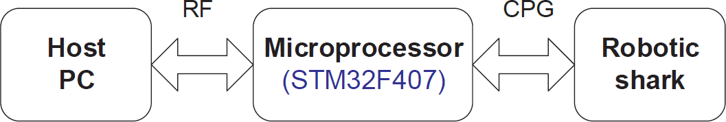
Control system framework of the miniature robotic fish
2.3. Hardware and software development
At the level of hardware design, as shown in Figure 4, an STMicroelectronics STM32F407 microcontroller is chosen as the main control chip. Specifically, it is based on the high-performance ARM® Cortex™-M4 32-bit RISC core operating at a frequency of up to 168 MHz. The Cortex-M4 core features a Floating point unit (FPU) single precision, which supports all ARM single-precision data-processing instructions and data types. It also implements a full set of DSP instructions and a memory protection unit (MPU), which enhances application security. A bidirectional RF module RF200 that can transfer messages between the embedded system and the PC is chosen. It communicates with the STM32F407 via UART interface.
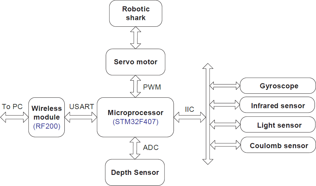
Hardware design of the online swimming control
In view of the fact that the working environment of the robotic fish changes dynamically and the power consumption and the size of the miniature robotic fish limit the processing capability of the microcontroller, we adopt a low-cost multi-sensor architecture to make the robotic fish adapt itself to the different environments. Currently, multiple different sensors involving a gyroscope, a depth sensor, three infrared sensors, two light sensors and a coulomb sensor are used. In particular, an MPU9150 is chosen as the gyroscope part. The MPU-9150 is the world's first integrated 9-axis motion tracking device, which combines a 3-axis MEMS gyroscope, a 3-axis MEMS accelerometer, a 3-axis MEMS magnetometer and a Digital Motion Processor™ (DMP™) hardware accelerator engine. In addition, the BH1750FVI is adopted as the light sensor for its large measurement range. A custom-built micro-pressure sensor is used as the depth sensor (see Figure 5). Three infrared sensors are installed on each side of the robotic fish to detect block area. Moreover, a MAX17044 is designed to monitor the capacity of the Li-Po battery. Finally, the generated control parameters from the host are transmitted to the STM32F407 via a wireless module (RF200), in which the CPG controller is solved in real time and PWM signals are subsequently output for servos.
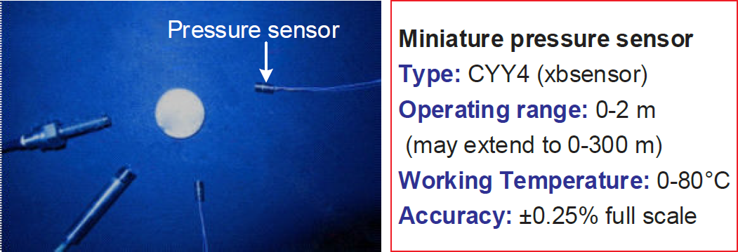
Photograph of the used pressure sensor
In terms of software design, an upper PC-oriented console is built based on the design pattern of.Net. Functionally, .Net is responsible for communication, sensor data display and swimming control. For the robotic fish, an embedded software system is built and a data communication protocol is developed to guarantee a stable data link between the PC and the robotic fish. Note that the PC and the embedded system communicate via the wireless module at present.
3. Motion Control Methods
This section will elaborate on the proposed bio-inspired CPG-centred control methods aided by feedback from various types of sensors.
3.1. CPG control model
Regarding the motion control of robotic fish, there are generally two methods: fish-body-wave method and CPG-based method [14]. In this paper, the latter is utilized to generate fish-like swimming. Specifically, an improved CPG model allowing free adjustment of phase relationship and directional bias is employed to execute flexible swimming.
Biological CPGs are neural circuits located in the spinal cord which are responsible for generation of cyclic muscle activation patterns such as respiration, chewing and legged movements during walking. CPGs can produce rhythmic signals without any rhythmic inputs from sensory feedback or higher control centres. Besides, CPGs have strong robustness, good adaptability and easily adjustable output signals [15, 16]. Therefore, CPGs are well suited to locomotion control dealing with multi-articulate or multiple degrees of freedom-related applications. For robotic fish mimicking fish-like swimming, CPGs are also extensively adopted. Compared with the traditional fish-body-wave method, CPGs as online gait generators only need to change output signals' characteristics and keep smooth and continuous even if parameters are abruptly altered. Thus, they can be easily applied to a wide range of fish-like movements, such as forward swimming, turning, diving and surfacing.
To date, many CPG models have been proposed. In this paper, a Hopf oscillator based on a CPG model is adopted [17–19]. By a simple adjacent coupling, the CPGs can finally be reduced with significantly fewer parameters. In particular, the CPGs have several specific parameters, which can be used to adjust the frequencies, amplitudes and phase lags of output signals. The detailed CPG model [20] is described as follows:

where the subscript i corresponds to the ith oscillator (i= 1,…,n) and n indicates the total number of neural oscillators in the CPG network. x
i
and y
i
denote the state variables of the ith oscillating neurons while ω
i
and A
i
represent the intrinsic oscillation frequency and amplitude. ψi denotes the phase lag of the output signal. h1 and h2 are positive constants of the coupling strength. z
i
and c
i
indicate respectively the output signal of the ith CPG and the magnification coefficient. In this paper, ωi = ω and ψi =
Considering that fish share the rhythmicity of swimming governed by CPGs, as shown in Figure 6, we utilize a CPG network coinciding with the physical configuration of the robotic fish. By setting the appropriate values for CPG parameters [21–23], the robotic fish can achieve diverse swimming controls.
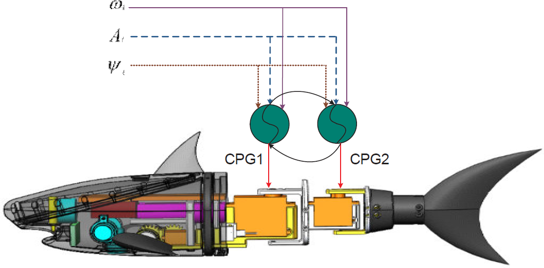
Topological structure of the employed CPG network
3.2. 3D motion control based on gyroscope compensation
In general, to achieve 3D locomotion aided by the pectoral fins, the robotic fish should maintain a certain forward speed. In particular, this speed is related to the length of the multi-link mechanism. In order to explore propulsive mechanism and performance of the two-link robotic fish, a 3D motion control method based on gyroscope compensation is proposed.
More specifically, CPG models are used to control the speed of the robotic fish. Considering that the CPG model in (1) is a continuous one, it has to be discretized for control implementation in the real-time embedded system. That is, a tailored version should be built to control the robotic fish. Since there are only two active joints on the fish tail, only two oscillators need to be designed.


As can been seen in (2)–(4), the subscript i corresponds to the ith oscillator (i=0, 1). x[i] and y[i] denote the state variables of the ith oscillating neurons while ω and A[i] represent the intrinsic oscillation frequency and amplitude. θ denotes the phase lag of the output signal. h1 and h2 are positive constants of the coupling strength. Z out [i] and c indicate respectively the output signal of the ith CPG and the magnification coefficient. z[i] is the offset of the CPG value, mid[i] is the middle value of the servo motor and ratio[i] is a coefficient that converts CPG data to servo motor position. To increase the speed of the robotic fish, either ω or A[i] could be set to a larger value. To make the robotic fish turn right or left, z[i] can be set to an appropriate value. When the robotic fish is swimming forward, z[i] should be set to zero. By (4) the position calculated by the CPG model is finally converted to the angle of the servo motor [24].
To achieve diving and surfacing, the pair of pectoral fins should be used. In particular, the robotic fish should first obtain a certain forward speed, making its head heavier than its tail in order for it to swim downwards; otherwise, it will swim upwards. Therefore, up-and-down motions can be implemented by changing the angle of the pectoral fins. When the robotic fish is commanded to swim downwards, the angle of the pectoral fins should be set as shown in Figure 7(a). In that case the surrounding water will generate a downward force on the pectoral fins, allowing the robotic fish to swim downwards. Otherwise, if it is set as shown in Figure 7(b), the robotic fish will receive an upward force that will drive it to swim upwards. Moreover, if a fast swimming mode is desired, it is preferred that the pectoral fins stay parallel to the water surface so as to reduce drag and increase swimming stability.

Schematic of performing up-and-down swimming. (a) Swimming downwards; (b) Swimming upwards.
Given that there are tough issues such as the interference of water, output signal error of CPGs and rotation error of servo motors, it is difficult for the robotic fish to swim straight in water. Thus, an output compensation method based on gyroscope feedback is proposed in this paper to reduce the swimming error caused. In particular, upon the start of forward swimming, the direction angle in which the robot will swim is acquired by sampling the output of the gyroscope. Considering that the gyroscope is positioned at the front of the robotic fish, the output direction angle will fluctuate around a certain value. If the robotic fish swims as straight as desired, the value should be the starting direction angle. Assuming that the compensate period is T, the sampled direction angle is averaged over a sampling period and compared with the destination direction angle. If it is the left side of the destination, the robotic fish will turn right and vice versa. This procedure is repeated until the current direction angle is equal to the destination so that the robotic fish swims as straight as possible. In such a way, the resulting direction error is gradually reduced in real time. However, there is still one issue remaining with regards to setting an appropriate compensation period. If it is too large, the resulting forward path will be parallel to the destination; too small a value will lead to an oscillating path which is not straight. As a consequence, the robotic fish will achieve 3D locomotion by a combined use of the CPG model and feedback information from the sensors.
3.3. Depth control based on pressure sensor feedback
As mentioned previously, through 3D motion control, the robotic fish is able to swim forwards, dive and surface, as well as turn freely. However, making the robotic fish swim at a given depth, i.e., achievement of precise depth control, is fundamental to being able to execute aquatic missions. Actually, with the equipped pressure sensor, the depth information of the robotic fish can be acquired and further used as a feedback signal for precise depth control [25–27].
Concerning the nonlinear control of the robotic fish, a fuzzy controller is built to obtain input of the CPG controller to realize depth control. The output of the CPG controller is utilized to drive servo motors in order to replicate fish-like propulsion and manoeuvring. The control framework that combines the fuzzy controller and the CPG model is illustrated in Figure 8. Here, e(k) denotes the input error, while ec(k) represents the derivative of the input error, as defined in (5):

Flow chart of depth control framework

where d d represents a predetermined depth position that the robotic fish will finally reach. dc(k) stands for the real-time measured depth of the robotic fish. With the fuzzy controller above, the robotic fish can ultimately reach a predetermined depth after a series of up-and-down movements.
3.4. Autonomous obstacle avoidance based on infrared sensor feedback
Due to the uncertainty of the water environment, it is necessary for the robotic fish to have the ability to detect the environmental information, such as target recognition, obstacle avoidance, temperature and danger detection. Of all these abilities, the robotic fish should particularly avoid obstacles in autonomous navigation. When the robotic fish bumps into other objects underwater, it will not only affect its swimming path, but, even worse, also destroy the robot itself.
In this paper, three infrared sensors are installed on the right, front and left sides of the robotic fish to detect obstacles underwater. If there are obstacles on the left of the robotic fish, it will turn right and vice versa. If there are obstacles in front of the robotic fish, it will turn back. If there is no obstacle, the robotic fish will swim forwards. An output table is designed based on the status of the infrared sensors. Let 1 be obstacle detected and 0 be none. The status of the three infrared sensors is from 000 to 111 –the first digit represents the status of the left infrared sensor, the middle digit is the front one and the third digit is the right one. The output data based on the status input are the offset values (z[0] and z[1]) in (2) and (3). The detailed relationship is summarized for easy reference in Table 2.
Output offset value based on status of infrared sensors

3.5. Autonomous navigation based on light intensity sensor detection
Light navigation is very useful in real-world applications, especially going through dark areas such as pipes or caves. On these occasions, the light intensity is low at the very start and will gradually increase upon approaching the exit. With the light detection sensor responsible for checking the change in the light intensity, the robotic fish is able to swim towards the exit. In addition, with the aid of the infrared sensor, the robotic fish can avoid obstacles successfully and reach the exit that has the strongest light intensity.
In this paper, two light detection sensors were installed at the front of the robotic fish. By sampling the light intensity data of the two sensors, the robotic fish can swim ahead autonomously. If the light intensity of the left side is stronger than that of the right side, the robotic fish will turn left and swim forwards. Otherwise, it will turn right and swim forwards. If the two sides are almost equal, the robotic fish will swim forwards directly. By the above defined rules, the robotic fish can achieve autonomous navigation with the aid of light sensors.
4. Experiments and Results
To verify the feasibility of the proposed miniature robotic design scheme and the control methods, some tests on the actual robot were performed in a pool with the dimensions 500 cm long, 400 cm wide and 150 cm deep.
First, a series of functional tests were carried out, including forward swimming, up-and-down swimming, automatic obstacle avoidance, light navigation and depth control. The result of depth control is illustrated in Figure 9, where the desired depth was preset as 40 cm. The depth error was further defined as the desired depth minus the measured depth. Statistical analysis of the depth data indicates that the robotic fish could maintain the desired depth from the 11th moment. After the steady-state depth errors were analysed, it was concluded that the mean depth error was 1.49 cm, while the standard deviation was 2.68 cm. Note that the positive depth error means that the pectoral angle of attack should be adjusted to control the robot to dive and vice versa. This testing result demonstrates that the fuzzy logic-based depth controller has a sensitive response and that the control errors are in the acceptable range. It lays out a foundation for the 3D swimming control.
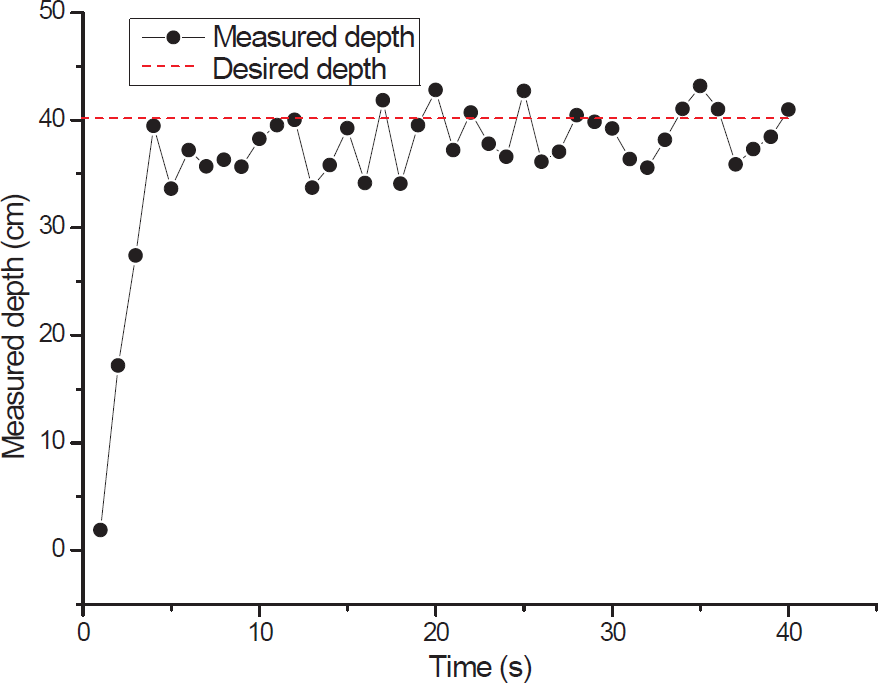
Experimental results of the depth control
Furthermore, the possibility of 3D swimming was examined. As expected, the robotic fish successfully executed a variety of 3D swimming behaviours and freely switched between them. A snapshot sequence of autonomous navigation based on all the sensors is demonstrated in Figure 10. This test lasted about 50 s, during which the robotic fish demonstrated various swimming patterns on the water surface or under water. In the experiments, the speed of the robotic fish varied from 0 to 0.5 m/s. With a battery capacity of 3,400 mAh, the robotic fish could maintain about one hour of free swimming. Tests indicated that a miniature robotic fish with two tail joints and a pair of artificial pectoral fins is suitable for free swimming in 3D underwater space. More importantly, a hybrid use of the CPG control and feedback information from multiple sensors substantially contributes to locomotion capability and intelligence of the robotic fish. Of course, more extensive strict experiments, particularly in the field, are also required to validate the formed mechatronic design and control methods in order to ultimately expedite real-world applications of the robotic fish as an effective underwater propulsion platform.

Snapshot sequence and swimming trajectory of autonomous navigation in 3D underwater space
5. Conclusion
This paper presents a design for a miniature, 35-centimetre long robotic fish with multiple sensors, which is propelled by a combination of two active joints and a pair of mechanical pectoral fins. More specifically, a hybrid control system framework combining one high-performance microprocessor and multiple sensors is first built. Next, 3D motion control methods primarily based on the CPG model and gyroscope compensation are proposed. In addition, depth control with pressure sensor feedback and autonomous obstacle avoidance with infrared sensor and light navigation are separately performed to enhance the intelligence of the robotic fish. Finally, preliminary test results verify the effectiveness of the presented design scheme and control methods.
Future work will concentrate on enhancing the robotic fish's intelligence by taking full advantage of sensing and signal processing capabilities of the embedded control system. Other work will include energy optimization by improving the CPG model and control algorithms so that the robotic fish can be competent for more complicated and durable missions in unstructured underwater environments. Of course, the multi-sensor scheme may be further analysed to provide inspirations for the design of bio-inspired underwater vehicles.
Footnotes
6. Acknowledgements
This article is a revised and expanded version of a paper entitled [Design and implementation of a smart robotic shark with multi-sensors] presented at [The 2015 International Conference on Climbing and Walking Robots, Hangzhou, China, 6-9 September, 2015]. This work was supported in part by the National Science Foundation of China (61375102, 61333016, 61573226), in part by the Beijing Natural Science Foundation (4161002), in part by the National Defense Science and Technology Innovation Fund of Chinese Academy of Sciences (CXJJ-16M110) and in part by the State Key Laboratory of Alternate Electrical Power System with Renewable Energy Sources under Grant LAPS16006.