
Abstract
Most path-planning algorithms are used to obtain a collision-free path without considering continuity. On the other hand, a continuous path is needed for stable movement. In this paper, the searched path was converted into a G2 continuous path using the modified quadratic polynomial and membership function interpolation algorithm. It is simple, unique and provides a good geometric interpretation. In addition, a collision-checking and improvement algorithm is proposed. The collision-checking algorithm can check the collisions of a smoothed path. If collisions are detected, the collision improvement algorithm modifies the collision path to a collision-free path. The collision improvement algorithm uses a geometric method. This method uses the perpendicular line between a collision position and the collision piecewise linear path. The sub-waypoint is added, and the QPMI algorithm is applied again. As a result, the collision-smoothed path is converted into a collision-free smooth path without changing the continuity.
Keywords
Introduction
The goals of path planning are to avoid obstacles and to find a path. The Probabilistic Roadmaps (PRM) [1] and the Rapidly exploring Random Trees (RRT) [2] algorithms are widely used in sample-based planning algorithms. These algorithms generate points and a collision-free linear piecewise path. The points are regarded as the waypoints of the mobile robot's movements. In addition, the collision-free linear piecewise path is considered as a collision-free G0 continuous path because this path consists only of straight lines. On the other hand, a high continuous path requires curves.
The G2 continuous path means a continuous velocity and a continuous acceleration of the robot's movements. If the velocity and acceleration are not continuous, slippage and over-actuation can occur, which can affect the robot movements in a real environment. Moreover, if a planned path has a vertex, the robot cannot follow the path while maintaining the velocity at the vertex. Therefore, the low continuous path cannot be an optimal path as regards time and dynamics. As a result, the path must consist of curves.
The continuity is defined in the geometry [3]. A G0 continuous path is simply connected for all sections. Sample-based searching algorithms (the PRM [1] and the RRT [4]) construct a G0 continuous path. A G1 continuous path matches the first-order differential values at each point. This path shares a common tangent direction and indicates that the robot and vehicle can have a continuous velocity. TheG2 continuous path has the same second-order differential values at each point. This path also shares a common centre of curvature, which means that the robot and the vehicle can move with continuous acceleration. Accordingly, the G2 continuous path is called the continuous-curvature path because the curvature can be obtained using the first-order differential values and second-order differential values. A G n continuous path indicates the equality up to then th differential values at each point.
To apply to a robot or a vehicle, Villagra et al. reported a smooth path and speed planning for smooth autonomous navigation [5]. Yang et al. proposed a continuous-curvature path-smoothing algorithm using cubic Bézier curves with reduced nodes [6]. Komoriya et al. suggested the trajectory design and control of a wheel-type mobile robot using a B-spline [7]. These reports are focused only on creating a smooth path. Therefore, the result of a path-smoothing algorithm can be a collision. The following studies evaluated a path-smoothing algorithm without collision. Laumond described finding a collision-free smooth trajectory [8]. Scheuer and Fraichard reported collision-free and continuous curvature path planning for car-like robots [9]. Ho and Liu suggested collision-free curvature-bounded smooth path planning using composite Bézier curves based on a Voronoi diagram [10]. These studies sought to obtain a collision-free and a smooth path simultaneously. Pan et al. also reported collision-free and smooth trajectory computation in cluttered environments using B-spline curves [11]. They constructed a smooth path from a linear piecewise path. In addition, they provided an example of a collision path from a path-smoothing algorithm, and improved the collision path to create a collision-free path using the proposed algorithm.
The aims of this paper can be divided into three categories. The first was to create a smooth path including the entire waypoint. Huh and Chang reported a path-smoothing algorithm using modified quadratic polynomial and membership function interpolation (QPMI) [12]. This algorithm can generate a path including the entire waypoint with simple calculations. This paper uses the QPMI algorithm to construct a curvature-continuous smooth path. The second aim was to check the collisions of the generated path. Pan et al. described a collision detection algorithm [11]. This paper use Pan's algorithm to the detection of collisions. The third was to improve the collision path to create the collision-free path. This paper proposes a new collision improvement algorithm for the QPMI algorithm. The proposed algorithm can avoid collisions by adding a sub-waypoint. The added waypoints modify the collision path to create a collision-free path.
In the simulation, the linear piecewise path from the PRM algorithm [1] was improved to create theG2 continuous path using the QPMI algorithm [12]. In addition, the first-order and second-order differential values at each waypoint are shown on the differential value's graphs. These graphs indicate that the robot and the vehicle can follow a smoothed path with a continuous velocity and acceleration. To verify the collision improvement algorithm, a collision path was made from the planned smooth path. The collision path is improved to create a collision-free path using the collision detection and improvement algorithm.
This paper is organized as follows: Section 2 reports the path-smoothing algorithms using the interpolation method and the requirements of the path-smoothing algorithms. Section 3 explains the characteristic of the QPMI algorithm. Section 4 proposes the collision detection and improvement algorithm. Section 5 reports the simulation results. Section 6 presents the conclusions.
Path-smoothing algorithm using interpolation
Collision-free smooth path
An interpolation is a mathematical field of numerical analysis. This method is used to construct new data points between a series of known data points. Many researchers have applied this method to prepare a path for moving a robot or a vehicle.
In path planning, the path must visit the waypoints. If the searching algorithm creates the waypoints, the smoothing algorithm should not alter the waypoints to prevent the mobile robots or vehicle from losing the waypoints. This is the difference between computer graphics and path planning. Many interpolation-based path-smoothing studies have used the method of computer graphics such as B-splines and Bézier curves.
B-spline and Bézier curves require control points to decide the curvature of the curves. If these methods are applied to smooth path planning, some waypoints must be used as a control point or else a new control point will be needed to decide the curvature. The smoothed path does not include the control points.
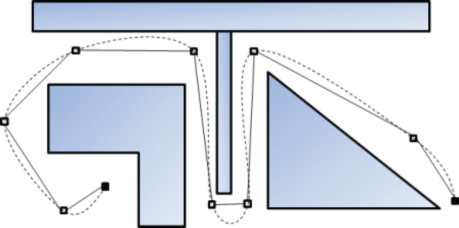
A sample-based path-searching algorithm produces the waypoints and the robot must visit the waypoints. On the other hand, the robot cannot visit those waypoints used as control points to decide the curvature. In Figure 1, the squares are the searched waypoints and the circles are the control points. The lines are the linear piecewise path, and the dotted lines are the continuous path using the B-spline method. The dotted lines only contact the control points. The control points are variable and the curves can be modified using the position of the control points. Therefore, the smoothed path is not unique, and the B-spline planned path might not visit the entire waypoint. For the movements of a robot or a vehicle, the planned waypoints and the searched linear piecewise paths using the searching algorithms guarantee a collision-free path. Therefore, if the smoothed path is close to the linear piecewise path, it is less dangerous than the path that does not visit the waypoints. To obtain a collision-free path, the path smoothing algorithm should follow the waypoints and the searched linear piecewise path faithfully.

Liner piecewise path using the searching algorithm (line) and the smooth path using a B-spline (dotted line)
The path in Figure 1 needs to be modified. The smoothed path with every waypoint is as follows:
In Figure 2, the dotted path visits every waypoint. This path is closer to the linear piecewise path than the B-spline-planned path (Figure 1). Therefore, the smooth path, by visiting every waypoint, is closer to the collision-free path.
If the paths in Figures 1 and 2 are placed on narrow passages, the path of Figure 1 can occur as the collision path as follows:

Liner piecewise path using the searching algorithm (line) with the smooth path contacting each waypoint (dotted line)
On the other hand, the path of Figure 2 does not give rise to a collision because this path follows the searching algorithm-planned linear piecewise path.
If the control points are moved, the smoothed path can become the collision-free path (Figure 3). In this case, another algorithm is needed to decide the position of the control point. Figure 4 shows the smooth path in the same environment. The path serves as a smooth path by following the guaranteed collision-free linear piecewise path. The smoothed path should approach the collision-free linear piecewise path as much as possible in order to decrease the probability of collision.

Collisions are created using control points
If the smoothed path is close to the searched linear piecewise path, the probability of collision decreases
This paper has the following purposes.
The smoothed path must contain the entire waypoint. The smoothed path should be closed to the linear piecewise path with continuity. The smoothed path should be able to check the continuity. If the smoothed path has a collision, the collision is detectable and can be improved. Simple calculations and unique solution. Simple geometry interpretation.
Items 1. and 2. mark the differences between other studies (e.g., B-splines and Bézier curves) and the proposed method. Item 3. is the necessary condition of the path-smoothing algorithm. Item 4. marks the main issue of this paper. This paper proposes a collision detection and improvement algorithm. Items 5. and 6. are important for implementing the proposed algorithm for a real system.
Modified quadratic polynomial and membership function interpolation
The QPMI algorithm [12] is a simple path-smoothing algorithm. This algorithm was developed to avoid Runge's phenomenon [3] and the weakness of spline interpolation. The QPMI algorithm can construct a G2 continuous path using just the quadratic polynomials and membership functions. Furthermore, the continuity of the planned path can be checked.
The quadratic polynomial can construct the shortest path for three waypoints with G2 continuity because it is the minimum-order polynomial that can connect three points for G2 continuity. In addition, it is a unique solution for three points. The QPMI-planned path consists of quadratic polynomials. Therefore, the planned path is the shortest G2 continuous and unique path with the given waypoints. Moreover, every waypoint is included in the planned path, unlike other algorithms.
The QPMI algorithm does not require the trigonometric functions or a high-order function to create a G2 continuous path. Therefore, it has a simple calculation. Additionally, the proposed algorithm can provide differential values, the curvature and the heading angle of the planned smooth path. These data can be used in designing the control algorithm.
Huh and Chang [12], however, did not prove the following two lemmas: the first is that the QPMI algorithm has a unique real number solution; and the second is that the continuity of the QPMI algorithm-planned path is decided by the continuity of each axis. This section will prove these two lemmas.
Unique real number solution of the QPMI algorithm
Lemma 1: The QPMI algorithm has a unique solution in the real number field.
Proof 1: The QPMI algorithm-planned smooth path


x(u) and y(u) express the variations in the x and y axes. The parameter u was defined as:

The parameter n is the visiting order of the waypoints. Equations (1) and (2) can be obtained using equations (4) and (5):


(2 ≤ n ≤ m − 1)
The parameter u is defined as follows:


The parameter u is a cumulative value, and is an increasing function. To obtain the inverse matrix of the parameter u, the determinant value should not be zero. The determinant of the parameter u can be obtained as follows:


Therefore, equation (9) can be solved as follows:

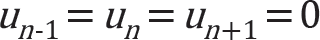
if un−1 = 0. In this case, equation (10) is changed to:

If un−1 = 0, then u n and un+1 are not zero according to (6). Therefore, equation (10) cannot be zero.
The second case is the case of un−1 > 0. If equation (10) is zero, equations (12) or (13) is satisfied.

On the other hand, in equation (6), un−1, u n and un+1 are not equal. Therefore, equation (10) cannot be zero. In addition, equation (13) is not satisfied because u n is not zero. Therefore, the determinant value is not zero in any case. As a result, Lemma 1 is proven. ▪
The continuity of the path from the QPMI algorithm is determined by the continuity of each axis. The QPMI algorithm uses the parametric method. This method separates each axis using the parameter u. To check the continuity of the planned path, the differential values of x(u) and y(u) are continuous.
Lemma 2: If x(u) and y(u) are continuous,
Proof 2: The continuity is determined by the matching of the differential values at each waypoint. If x(u) is G2 continuous, dx(u) and d2x(u) have connected graphs in the entire section. If y(u) is G2 continuous, dy(u) and d2y (u) have connected graphs. The first-order and second-order differential values of
Collision detection and improvement algorithms for the smooth path
The piecewise linear path is a collision-free path using the path-searching algorithm. Generally, this path does not require a collision-check. On the other hand, the smoothed path requires a collision-checking process because collisions can occur while constructing a smooth path using the path-smoothing algorithm. Figure 5 presents the case of a collision of the smooth path.

Collision-free linear piecewise path (line) and smoothed path (dotted line). A collision occurred at the dashed circle.
In Figure 5, the line is the linear piecewise path from the path-searching algorithm. The dotted line is the smoothed path using the QPMI algorithm. A collision occurs between P 3 and P 4 . The collision-checking algorithm must detect the collision of the smoothed path. In addition, the path should be improved to create a collision-free path.
The simplest collision-checking algorithm checks the collision of the path by discrete samples. The idea of an ‘efficient spline collision detection algorithm’ [11] is used in this paper.
Given the smoothed path

If a collision is detected, equation (14) is changed to equation (15):

The proposed collision-checking algorithm is as follows: let d(P(u), B) be the distance between P(u) and B. φ is a boundary of the robot. The bound of the robot can be defined as the size of the robot or the sensing area of the robot. If a collision is detected, ρ < 1. Equation (16) is a collision-checking equation:

In equation (16), the bound of the robot φ should be smaller than the distance between P(u) and B. Algorithm 1 is described as a collision-checking algorithm.

Collision-checking algorithm
This study used Algorithm 1 to check the collision; u c is the collision position. If the path is not collision-free, the collision position u c is sent to Algorithm 2 for improving the collision of the path. If this path is a collision-free path, Algorithm 1 returns the collision-free path.
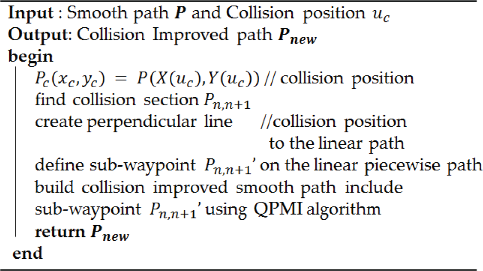
If a collision occurs, a path improvement algorithm is needed. In Figure 6, a collision has occurred in a P34 section. The aim of the collision improvement algorithm is to correct the smoothed path closer to the linear piecewise path in a collision section, because the linear piecewise path already guarantees the collision-free path using the path-searching algorithm. Therefore, the smoothed path can be a collision-free path which is as close as the linear piecewise path. Figure 6 is an improvement on the smoothed path using the smoothed path moved to the linear piecewise path.

(a) Collision of the smoothed path; (b) improved collision path
In Figure 6, the first step was to finding a perpendicular line between the collision position and the linear piecewise path. The blue dashed line is the perpendicular line. The second step is to create a sub-waypoint on a crossing position of the linear piecewise path and the perpendicular line. The crossing position is defined as sub-waypoint P3,4′. The third step is to reconstruct the smooth path including the sub-waypoint using the QPMI algorithm. This process is described as Algorithm 2.
Collision improvement algorithm
Algorithm 3 is the collision-checking and improvement algorithm using Algorithms 1 and 2.

Collision-free path-smoothing algorithm
Algorithm 3 can be used for collision checking and improving the smooth path. Algorithm 1 checks the collision and Algorithm 2 improves the collision path to create the collision-free path. These two algorithms are combined as Algorithm 3. In this paper, Algorithm 3 is called the ‘Collision-free Checking and Improvement’ (CCI) algorithm.
The maximum checking count value is the number of collision checks. In the case, where it is impossible to find a collision-free path using the proposed algorithm, Algorithm 3 can be an infinite loop. To avoid an infinite loop, the checking count's maximum value needs to be checked.
In this section, the linear piecewise path is converted to the G2 continuous path using the QPMI algorithm. In addition, the proposed CCI algorithm is applied to this smooth path.
A simulation map has a narrow passage that makes it collide with the obstacle. The PRM algorithm is used to obtain the linear piecewise path. This algorithm is implemented using the MATT AB toolbox of [13]. Figure 7 presents the simulation map, and Figure 8 shows the result of the PRM algorithm.

Simulation map with the start point and goal point. The red blocks are obstacles.
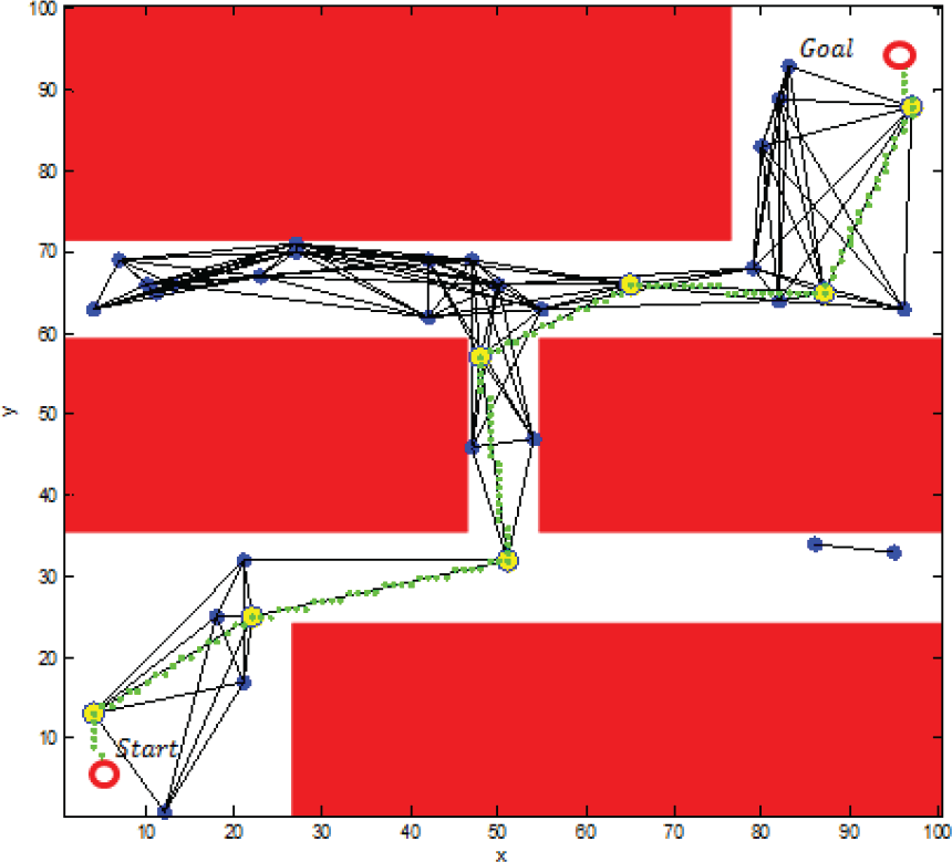
Result of the PRM algorithm. The green line is the searched linear piecewise path using the PRM algorithm.
The searched collision-free waypoints are as follows:
The QPMI algorithm requires a distance parameter u. The set of u is as follows using equation (3).
Searched position using the PRM algorithm. P1 is the start point and P9 is the goal point.

Searched position using the PRM algorithm. P1 is the start point and P9 is the goal point.
Set of parameter u

Equations (4) and (5) construct the quadratic polynomials. These polynomials are shown in Figure 9 (a). In addition, Figure 9 (b) presents the result of the QPMI that combined the quadratic polynomial and membership function.
Graph of the parametric quadratic polynomials (a), and a merged graph (red line) using the membership function (b)
The QPMI algorithm proffers variations of x and y and the differential values of them. In addition, the curvature and the heading angle can be obtained.
Figure 11 shows the graph of x and y.

(a) graph of u vs. x; (b) graph of u vs. y
In Figure 12, the graph connects the entire section. This graph indicates that the smoothed path is the G1 continuous path.
Figure 12 presents the first-order differential values of x and y.
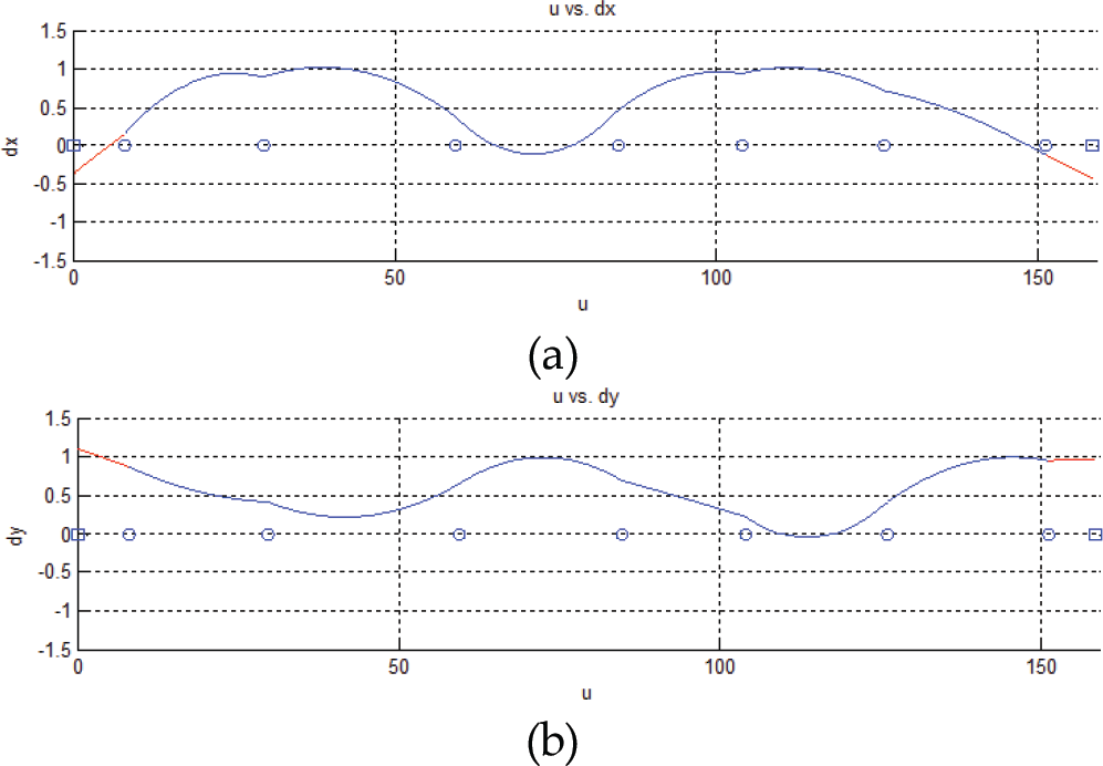
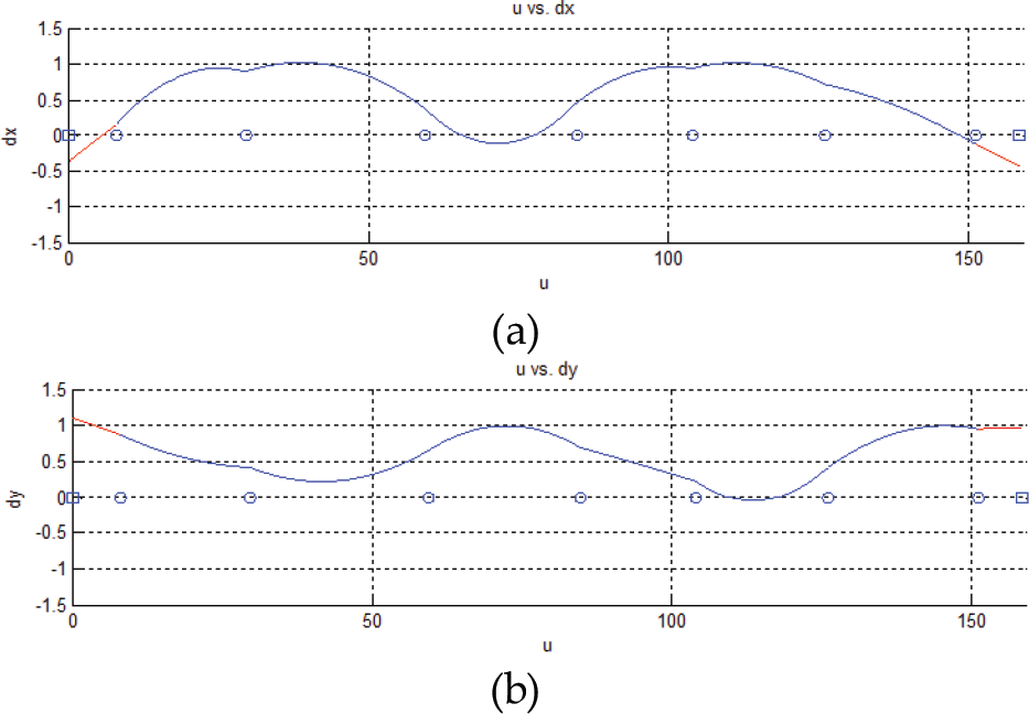
(a) graph of u vs. dx; (b) graph of u vs. dy
The condition of the G2 continuous path is that the second-order differential values should be contacted at each waypoint. To check the G2 continuous path, the graph of the second-order differential values was obtained. Figure 13 presents a graph of the second-order differential values.

(a) graph of u vs. d2 X; (b) graph of u vs. d2 y
Figure 13 show that the smoothed path is the G2 continuous path.
The curvature graph can be obtained, as shown in Figure 14. The graph is as follows:

Graph of u vs. curvature
The G2 continuous path is also called the ‘curvature continuous path’. In this simulation, the first-order and second-order differential values are matched at each waypoint. These values construct the continuous curvature. In Figure 14, the curvature graph is continuous.
Figure 15 shows the heading angle graph. This graph has a continuous form. This means that the path can follow with continuous movement.

Graph of u vs. the heading angle
In section 5.1, the smoothed path proved the G2 continuous path. In addition, the path was analysed using the QPMI algorithm. On the other hand, the searched waypoints can be placed at an obscure position in a real situation. In this case, the smoothed path cannot guarantee a collision-free path despite the linear piecewise path being a collision-free path. In this section, Figure 10 was modified to create the collision path for the collision detection and improvement simulation. This simulation assumes that the searched linear piecewise path is a collision-free path, but the smoothed path sees a collision. If P5 is moved, the liner piecewise path can be modified as Figure 16 (b).
The QPMI algorithm was applied to the modified path and the path was changed to the smoothed path. On the other hand, the smoothed path has a collision despite the linear piecewise path being the collision-free path. Figure 17 shows this phenomenon.
Figure 10 presents the final result

G2 continuous path using the QPMI algorithm

Original path (a) and modified path (b). Both paths are the collision-free path

Collisions occur on the smoothed path. The red circle is the collision position.
To improve the collisions, the CCI algorithm was applied. The first collision position was P c (46, 55.25) when u c =81.5.
The linear piecewise equation of P4 to P5 is expressed as (17) and an equation of the perpendicular line is shown in equation (18):


The sub-waypoint can be obtained using equations (17) and (18). The sub-waypoint was P4,5′(47.869,55.484). Figure 18 shows the collision position, the perpendicular line and the sub-waypoint.

The collision improvement algorithm is shown. The smoothed path makes the collisions. The perpendicular line is constructed between the linear piecewise path and the collision position. A cross-position of the perpendicular line and the linear piecewise path is decided to create the sub-waypoint.
Finally, the QPMI algorithm was applied including the sub-waypoint. Figure 19 demonstrates the collision-improved path. The red-dashed path is a collision-smooth path. After applying the CCI algorithm, the collision problem is solved as the blue path. This path includes P4, P45, P5 and P6.
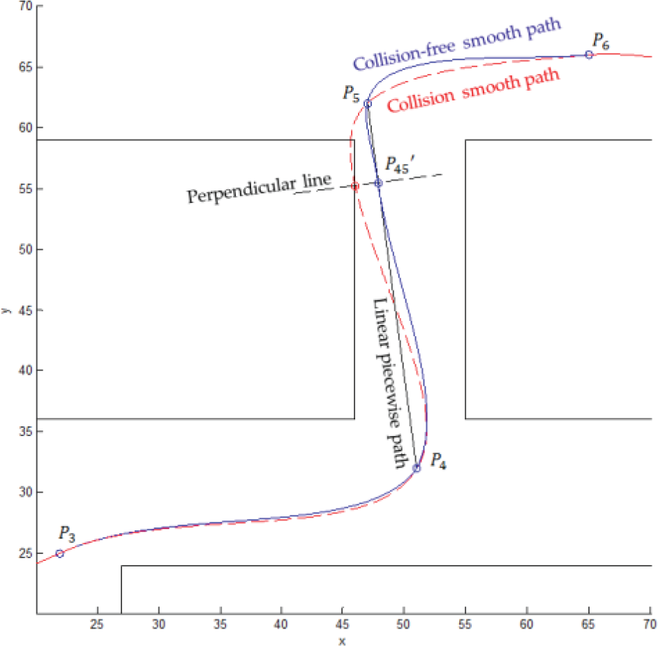
Collision path (red-dashed line) and collision-free path (blue line). The collision-improved path contains the sub-waypoint. As a result, the path is moved to the collision-free linear piecewise path.
Figure 20 presents the final result of this simulation. The collision position can be avoided using the path that is moved to the sub-waypoint. This path can be decided as the collision-free path using the CCI algorithm.

Collision-improved path using the CCI algorithm
In this simulation, the QPMI algorithm is demonstrated. The map has a narrow passage. The PRM algorithm searches for the collision-free linear piecewise path with low continuity. The QPMI algorithm constructs the smooth path and checks the continuity. As a result, the linear piecewise path is converted to a G2 continuous path.
To prove the CCI algorithm, the smooth path is modified to create the collision path. The first step is the detection of the collision position. In the next step, a perpendicular line is constructed between the collision-free linear piecewise path and the collision position. The sub-waypoint is decided at the cross-position on the collision-free linear piecewise path and the perpendicular line. Finally, the QPMI algorithm is applied again to create a smooth, collision-free path. The collision-free G2 continuous path can then be obtained.
Most search algorithms do not consider the continuity of the path. The QPMI algorithm aims to construct a continuous path from a searched, collision-free linear piecewise path. The general methods for constructing a continuous path is the B-spline and the Bézier curve, which are widely used in computer graphics. On the other hand, these do not contain all the waypoints because some waypoints should be used to create the control points that decide the curvature.
In this study, the QPMI algorithm was used to create the smooth path. This algorithm provides the G2 continuous path-smoothing algorithm, the differential values, the curvature and the heading angle. These data can be used to design the control algorithm of the mobile robots or vehicles. Furthermore, the result was unique and the calculations are simple because this algorithm used only the quadratic polynomials, without trigonometric functions or high-order polynomials. Therefore, the calculations can be simple. These features do not require high-performance hardware. In addition, unlike some other path-smoothing algorithms, the QPMI algorithm constructs a smooth path containing all the waypoints. During the path planning, visiting the waypoints is important.
The QPMI algorithm was required to prove two lemmas. The first is that the planned path is unique. The second concerns the continuity of the planned path. This paper proved these two lemmas.
The searched path using the searching algorithms is a collision-free path. Although this path is a collision-free path, the smoothed path cannot be decided by the collision-free path. The CCI algorithm was proposed to check the collisions in the smoothed path. The CCI algorithm can detect the collision position using a simple method. If the smoothed path has a collision, it can be improved using this algorithm by approaching the smoothed path to the linear piecewise path. The perpendicular line including the collision position and the linear piecewise path decides the sub-waypoint for moving the collision-smooth path to create the linear piecewise path. If a sub-waypoint is obtained, the QPMI algorithm can be applied again. As a result, the collision-smooth path is improved to create a collision-free smooth path maintaining continuity.
The goals of this paper were archived. The QPMI algorithm provided the path containing the entire waypoint, the smoothed path was approached to the linear piecewise path, the continuity checking was possible, the collision-checking and improving algorithm was proposed. the proposed algorithms are simple, unique and having simple geometry interpretation.
In this paper, the QPMI and CCI algorithm were applied to the 2D plane. These can be used for a mobile robot, vehicle, a game algorithm and for computer graphics without complex calculations. In addition, these algorithms can be expanded to a 3D space. In this case, it will be possible to use an aerial robot and aircraft to create a G2 continuous trajectory for visiting all the waypoints.
Footnotes
7.
This study was supported by the National Research Foundation of Korea (NRF) grant funded by the Korea government (MEST) (no. 2012-0005564).