
Abstract
This paper offers a bio-inspired trajectory generation method for UAV/MAV perching (i.e., the final approach to, and landing on, a target). The method is based on tau theory, which was established based on the study of the natural motion patterns of animals (including humans) when they approach a fixed or moving object for perching or capturing prey. In our research, tau theory is applied to the trajectory generation problem of an air vehicle for perching on a target object. Three bio-inspired strategies, namely the tau in the action gap strategy, the tau coupling strategy and the intrinsic tau gravity strategy are studied for perching tasks. A key parameter of the method inspired by biological systems is discussed. Two perching scenarios, one from a flight state (with non-zero initial velocity) and one from a hovering state (with zero initial velocity), are studied. Numerical simulations with a rotary vehicle are presented as examples to demonstrate the performance of the proposed approach. The simulation results show that the resulting flight trajectories meet all the desired requirements for the vehicle in perching on an object.
1. Introduction
Unmanned aerial vehicles (UAVs), including micro air vehicles (MAVs), increasingly play a significant role in many applications, such as searching, rescue, inspection, surveillance, and reconnaissance [1]. More and more challenging tasks, such as fast approaches to and precisely landing or perching on a desired spot, are expected to be performed by UAVs. To successfully accomplish these challenging tasks, UAV technologies, including path planning technologies, need to be further advanced. Currently, most path planning methods are based on waypoint guidance [2–3], which mainly care about where the way points are on the pathway. Few are concerned with the time taken by UAVs moving from one point to another, and they require complicated time optimization methods [4]. If the approaching path cannot be calculated quickly enough or is not considered, the UAV may not be able to perform a task satisfactorily, such as perching on a quickly escaping target object reliably and agilely, like a bird.
Unlike the traditional controllers of UAVs, the biological control mechanisms of birds have been optimized through millions of years of natural evolution and, hence, they allow birds to perform many perching or else other agile flight tasks accurately and robustly. A seagull can easily land on a small reef; an eagle can complete a capturing action precisely and in a short time. Therefore, we have good reason to learn from nature in looking to improve UAV technologies. There have been a few bio-inspired techniques related to UAV perching reported in the literature recently. Stanford University [5] developed an autonomous perching UAV system which is capable of landing on a vertical wall. MIT presented a novel mechanism for a fixed-wing UAV to perch on a power line [6]. The University of Pennsylvania also designed a robust perching and landing mechanism mimicking the functionality of bird feet [7–9]; they have also demonstrated successful perching on a flat surface. A passive perching mechanism was designed by the University of Utah [10] which can be used for a UAV to perch on objects of different shapes. These recent research efforts, and their vast potential for UAV applications, are currently motivating further interest and developments in the area of UAV flight dynamics and control. However, and regarding UAV perching, most of the research efforts so far have been focused on the biomimetic design of perching mechanisms [11–14]. To the best knowledge of the authors, there has not been a bio-inspired trajectory generation strategy mimicking natural bird perching for the UAV perching problem. The research work reported in this paper is intended to fill this gap.
When birds, as well as other animals, are approaching an object to perch upon or for capture, they naturally use predictive timing information specified by their visual cues to guide and adjust their actions. One important piece of information that researchers often focus on is the time-to-contact (TTC) which is sometimes also referred to as ‘time-to-collision’ or ‘time-to-closure’ [15]. TTC is defined as the time remaining before an anticipated contact between the approaching animal and the target object. Research into the perceptual mechanisms of biological systems has been going on for decades and many useful results have been generated [16]–[19]. Based on these results, Lee introduced tau theory [20], which proposed that the variable tau could be used to represent the TTC in animals' visual systems. Tau was defined as the inverse of the incoming object's relative rate of expansion on the retina [21]–[23]. Recently, Lee proposed a general tau theory, which suggested that tau information exists not only in animals' perceptual mechanisms but also in the guidance of animals' general movements [24]. This finding has been verified through both mathematical analysis and some experimental tests [25]–[28], and it has inspired robotics researchers to apply tau theory in order to potentially enhance robotics control technologies. Jump and Padfield found that pilots use tau-guidance strategies for piloting airplanes [29], and Farid and Ahmed tried to apply tau as a variable for the feedback control of the docking and landing of a UAV [30].
In this project, we develop new bio-inspired perching strategies for a rotary UAV in enabling perching on a target object based on tau theory. Differentiating from the most common trajectory planning strategies, our approach follows similar strategies to those that birds usually use for their perching actions in nature. In this paper, we used dynamics simulation and analysis to demonstrate that the resulting motion trajectories can guide a UAV to successfully accomplish a desired perching task.
2. Tau Theory-based Guidance
2.1 General tau theory
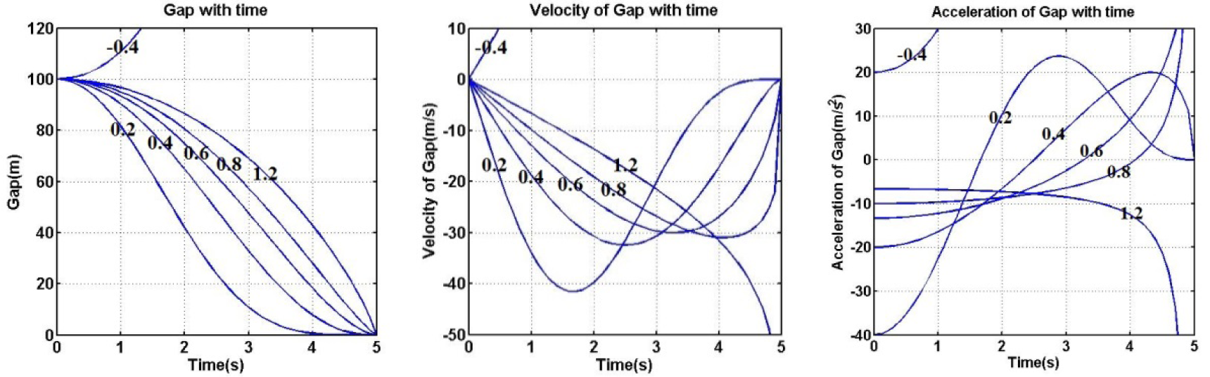
Lee [20] concludes that a key aspect of animal movement in approaching a target is goal-directed. If a motion gap is defined as the difference between the animal's current motion state and its target state, then all the intended control actions are made for the purpose of closing the motion gap. Based on [20], the tau of a motion gap is defined as:

where x(t) is the motion gap at time t and ẋ(t) is the derivative of the motion gap with respect to time.
2.2 Basic strategies
The guidance strategy that we are proposing is a form of perching guidance based on tau theory which assumes that we can predict a future motion state based on the known current motion state and the known final target state. There are three basic strategies under the approach [33].
2.2.1 Strategy with tau in the action gap
In this case, we assume that the UAV has arrived at an initial location in the air to descend upon the target object (or location) and that it is ready to descend. We generate a descending trajectory, starting from the initial location with a nonzero speed and ending right upon the target object with a speed of zero for a no impact landing. Since tau extrapolates how an action is to be changed, it provides information for prospectively controlling the action gap. Lee found that the only information needed for an animal by instinct in order to control an on-going descent action is the time rate of tau. It has been observed that animals tend to keep the time rate of tau constant as their control goal in descending upon a target [24], namely:

where k is a constant. Equation (2) is a basic tau law in the action gap from Lee's tau theory. From this, we have:

where τ0 is the initial value of tau, which in turn is:

and x0 and ẋ0 are the initial position and speed of the vehicle, respectively. Substituting (1) into (3), we get:
which leads to:

From equation (6), we can find the motion consequences with respect to different k values in Table 1.
Motion consequences with different k values (in the table, C is a constant while td is the final time)

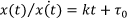
Table 1 and Figure 1 show the trends and time histories of x, ẋ and ẍ with different k values, from which we learn that only the case of 0 < k < 0.5 (the final time td = −τ0/k) meets our desired control goal, which is to land on the target with zero relative speed and acceleration, and thus without impact or collision.

Time histories of x, ẋ and ẍ with different k values (k=−0.4,0.2,0.4,0.6,0.8,1.2)
2.2.2 Strategy with tau coupling
In reality, multiple gaps exist and they need to be closed at the same time. In such a situation, the tau coupling principle is used. For example, when we need to close two translational gaps, namely, x(t) and y(t), the two corresponding taus will be kept at a constant ratio kx,y during the course of the approaching action, namely:

With this in mind, we can find the y trajectory as follows:

where a constant C is defined as C = y0/x1/k x,y 0.
Similarly, we can find the motion consequences with respect to different kx,y values in Table 2.
Motion consequences analysis with different kx,y values

The above results indicate that when 0 < kx,y ≤ 0.5 or kx,y = 1, the distance, velocity and acceleration of the y gap will became zero with the closure of the x gap. This meets our expected control goal, which is to close the x and y gaps simultaneously with a smooth landing (i.e., landing with zero relative velocity and acceleration).
2.2.3 Strategy with intrinsic tau gravity guidance
The difference between this case and the previous two is that the perching starts from a hovering position (zero velocity) and ends smoothly and precisely upon the target location. This means that the UAV will first accelerate and then decelerate in the course of closing the gap or gaps. With Lee's theory, this can be dealt with by a method called ‘intrinsic tau gravity guidance’ [20]. Tau theory assumes that such movements are guided by tau-coupling between the x gap and the intrinsically generated guiding gap. This can be described as follows:

where kx,y is a constant in the tau coupling which determines the relevant kinematics of the movement, and τ g (t) specifies the time of the gap to be closed under a constant acceleration. Since gravity is a major influencing factor on the animal's motion, τ g (t) is a function rooted from the ecology of animals. τ g (t) can be derived from the dynamics equation of free-fall motion under gravity acceleration g, namely:


where td is the time duration of the entire trajectory. We can find the solution of x by the tau coupling strategy as follows:

Table 3 and Figure 2 show the motion trends and time histories of x, ẋ and ẍ for different kx,g values. Therefore, we can conclude that only when 0< kx,g ≤ 0.5 and kx,g = 1 will the UAV land exactly and smoothly on the target location.
Motion consequences analysis with different kx,g values (in the table, td is the final time of movement)

Time histories of x, ẋ and ẍ with different kx,g values (kx,g=−0.4,0.2,0.4,0.6,0.8,1.2)
3. UAV Kinematics and Dynamics
3.1 Rotor Modelling
A quadrotor has four rotors and each rotor has an angular speed ω i producing a vertical force Ti according to:

Experiments with a fixed rotor for our UAV at steady state confirmed that kT ≈ 1.46*10−5 kg.m/rad2 [31]. Each rotor also produces a moment described by:

In our system, the motor constant kM is 3.8*10−7 kg.m2/rad2, which was experimentally determined. The moment and thrust can therefore also be related through the constant kTM:

3.2 Kinematics Modelling
To simplify the modelling of the system, the mass of the leg mechanism will be considered as a part of the quadrotor's mass but the kinematics of the mechanism will be exactly modelled. The coordinate systems and a free body diagram of the quadrotor are shown in Figure 3. We designate the world reference frame by Oned (north-east-down), in which the xw and yw axes are aligned respectively with the north and east directions, and the zw axis vertically points downwards. The UAV body-fixed frame is designated by Oabc (aircraft body centred), and has its origin coincident with the quadrotor's centre of gravity.

NED and ABC reference frames
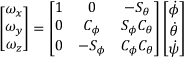
For a quadrotor, the angular motion around the three rotation axes is represented by six state-variables: three Euler angles [φ θ ψ] (roll-pitch-yaw) and three angular velocity components around the three axes of the ABC frame [ωx ωy ωz]. We use the 3–2–1 (Z-Y-X) Euler angles to represent the rotation of the quadrotor in the world frame. Assuming that the rotation matrices corresponding to the individual Euler angles are R′(φ), R′(θ) and R′(Ψ), then the rotation matrix R that represents the orientation of the coordinate frame Oabc with respect to reference frame Oned is:

where Cφ and Sφ represent abbreviations of cos(φ) and sin(φ), respectively. Similar abbreviations apply to θ and ψ.
The angular velocity components of the quadrotor, ωx, ωy and ωz, are related to the derivatives of the roll, pitch and yaw angles, as follows:
3.3 Dynamics modelling
Assuming that the quadrotor is a symmetric rigid body, its equations of motion can be written as:


where Fnet and Mnet are the resultant force and moment acting on the quadrotor, respectively, I is the inertia matrix of the quadrotor expressed in the body-fixed frame, and ω is the angular velocity of UAV, also expressed in the body frame. To keep the model simple, the Coriolis and aerodynamic forces (e.g., air drag) are ignored. Thus, the gravity force (G) and the four thrust forces (Tp) are the only forces acting on the UAV [32]. The resultant force is:

where T1 through to T4 are the thrust forces of the four rotors.
From equation (19), we have:

where L is the distance from the centre of the rotors to the centre of gravity of the quadrotor.
4. Trajectory Generation for Perching
In Section 2, we presented three bio-inspired motion planning strategies which resulted in closing the motion gaps smoothly (without impact or collision). For the generation of a perching trajectory, we assume that the tau can be tracked (estimated from the real-time data measured by GPS, cameras, an IMU and/or other navigation sensors).
Initially, we assume that
4.1 Perching from a flight state
When a vehicle is perching in relation to a target location with an initial velocity v0, we assume that d is the distance gap (the action gap in this case). Based on equation (6), we can calculate the remaining distance gap d(t) using:

where τ0=d0/v0 and d0 is the initial distance gap.
We can enable the UAV to approach a target along a straight-line trajectory as shown in Figure 4. The position of the UAV at time t can be determined by:


Perching upon a target along a straight-line trajectory
The trajectory, as shown in Figure 5, is generated by simulation assuming k=0.4, which represents the value observed from experiments with animals [23, 24]. We assume that the starting point is

Perching trajectory (left) and the UAV kinematics (right)

Pitch angles of the UAV during movement

Thrusts of the rotors (left) and the thrust difference of Rotor 1 and Rotor 3 (T1–T3) (right)
From the kinematic model presented in Section 3, we can obtain the attitude of the UAV. Because the vehicle does not need to change direction in this case, only the pitch angle of the UAV is changed during flight. As shown in Figure 6, we can see that the trajectory of the pitch angle is smooth but that the part near the end of the flight time changes sharply, which means that the thrust of the rotors (shown in Figure 7) becomes very large during this time. We can see that the thrust of Rotor 1 sharply increases while that of Rotor 3 sharply decreases. This is not a good result. Considering that only k could be set among the parameters in equation (6) what could be changed is only the k value in equation (6) with the same condition, we will try to change the k value next.
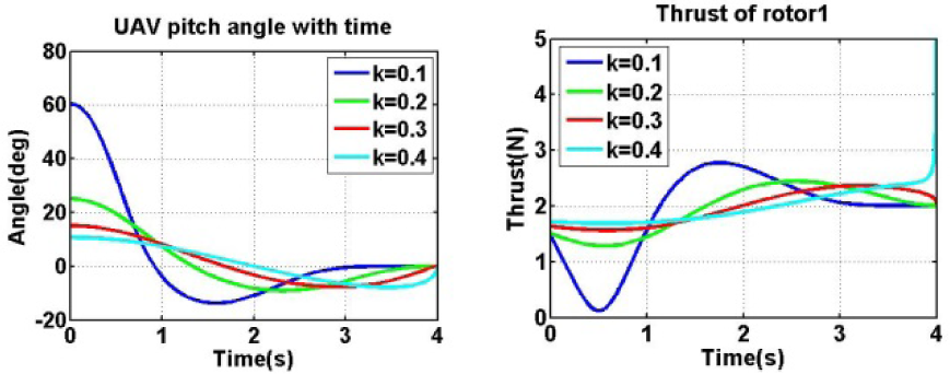
Based on the analysis in Section 2, k can change from 0 to 0.5 for smooth perching. We present simulations with four different k values (namely, 0.1, 0.2, 0.3 and 0.4). The results are shown on Figure 8. We found that a k value nearer to zero is better than that nearer to 0.5. Since k is related to the flight time, the smaller that the k value is, the longer the flight time will be. A smaller k value means that the UAV has more time to change its attitude during flight.
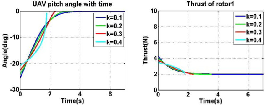
Pitch angles of the UAV (left) and the thrust of Rotor 1 (right)
4.1.1 Perching with tau coupling
In some applications, we want a UAV to arrive at a destination with a desired orientation. This means that we have to close an angular gap during the perching process as well.
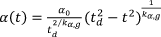
As shown in Figure 9 (left), the last portion of the flight trajectory approaching the ground is necessarily flat for a fixed-wing UAV because this type of UAV needs such an approaching trajectory for a safe landing. However, a rotary UAV, such as a quadrotor, does not require such a long landing path. Instead, a vertical landing is more appropriate. In this case, as shown in Figure 9 (right), the α angle is defined as an alternative angular gap to replace the original angular gap (i.e., the γ angle defined in Figure 9) [18]. The corresponding path shows that the last portion of the trajectory is almost vertical, which is suitable for a rotary vehicle on a perching task. In this case, we can simultaneously close two gaps, including a distance gap d(t) and an angular gap α(t). Using the tau coupling strategy described by equation (17), we can calculate the angular gap in terms of time t as follows:

Perching with angular coupling: (left) the tau path based on closing the γ angular gap for landing, as in the case of an airplane; (right) the tau path for perching based on closing the α angular gap
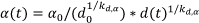
where kd,α is a constant ratio of the distance gap over the pitch angle gap, which will be determined by the criteria of the tau coupling strategy.
Combining the distance gap equation (22) and the angular gap equation (24), we get the

where:
and diag(•) represents a diagonal matrix.
It should be pointed out that, in general, the speed vd of closing a distance gap is not the same as the velocity of the vehicle at any instant because the vehicle may not fly straight towards the target all the time. Because the vehicle is decelerating, we can calculate vd according to:

where v0 is the initial velocity of the UAV.
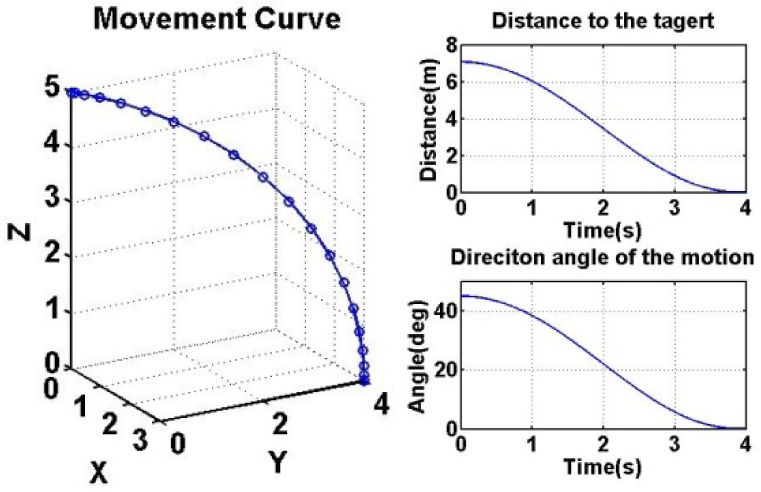
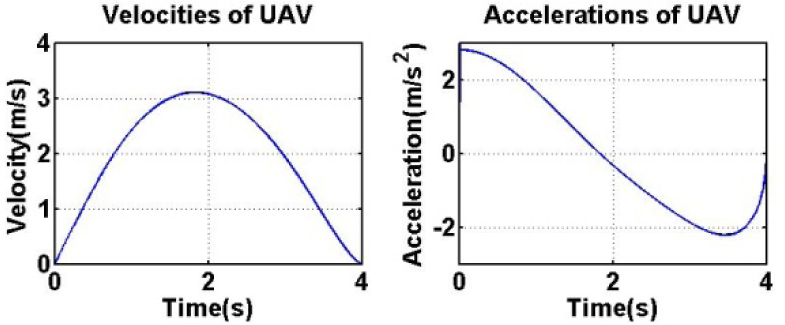
For simulation, we assume that k=0.4 and kd,α=0.4. Other parameters are the same as those above. The resulting 3D trajectory is shown in Figure 10 (left) and the distance and angular gaps are shown in Figure 10 (right). The resulting velocity and acceleration of the vehicle are shown in Figure 11. Obviously, the trajectory is smooth and reaches the target location at the end of the flight. As shown in Figure 12, we can see that the pitch angle of the UAV is reduced to zero smoothly. All the thrusts of the rotors shown in Figure 13 (left) change continuously along the trajectory and reach a value equal to a quarter of the UAV's weight, which means that the quadrotor is in static balance. As the difference in the rotors' thrusts is small in Figure 13 (left), the thrust difference of Rotor 1 and Rotor 3 is shown in Figure 13 (right).

Perching trajectory (left) and gaps (right) for the coupling case

UAV velocity and acceleration for the coupling case

Pitch angles of the UAV during movement
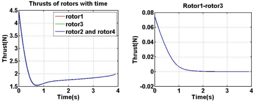
Thrusts of the rotors (left) and the thrust difference of Rotor 1 and Rotor 3 (T1–T3) (right)
In conclusion, there are two ways to keep the UAV stable under the same conditions. One is to keep the k value close to zero, while the other is to use the tau coupling strategy. In fact, based on the analysis in Section 4, a slight collision with a k value within 0.5~1 is suitable in many cases of landing and perching. If k is initially close to 0.5, it might be more easily changed smoothly by the control system within the range of [0.5, 1]; however, if k is initially close to zero, it is difficult to change smoothly. Therefore, the tau coupling strategy is preferable for practical use.
4.1.2 A 3D case
In order to present a full 3D case where all three Euler angles of the UAV change during flight, we add one more angular gap to what has already been discussed in the tau coupling strategy. As shown in Figure 14, if we need the UAV to change its heading during perching as well, we must use another angular gap β(t) in the tau coupling strategy. As before, we can calculate the angular gap in terms of time t as follows:
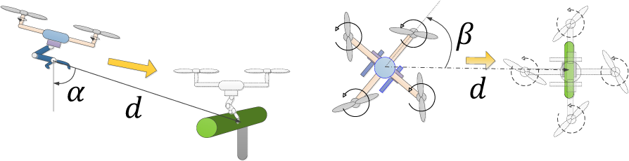
Perching upon a target along a straight-line trajectory
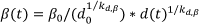
where kd,β is a constant ratio of the distance gap over the angular gap.
Combining equations (22), (24) and (27), we get the

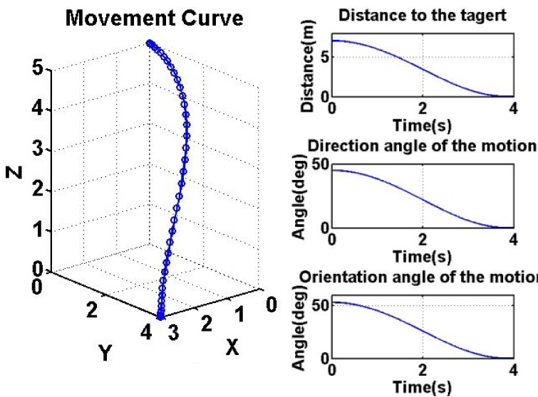
The resulting trajectory is shown in Figure 15, if we assume that k = 0.4 and kd,α = kd,β = 0.4. The motion trajectory is shown in Figure 16, the attitude is shown in Figure 17, and the thrusts of the rotors are shown in Figure 19. Figure 18 gives a snapshot of the UAV for a few time instants along the trajectory.

Perching trajectory (left) and gaps (right) for the 3D case

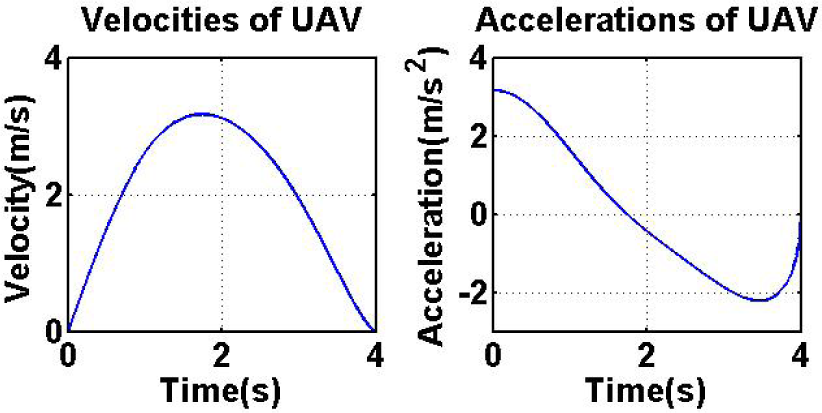
UAV velocity value and acceleration value for the 3D case

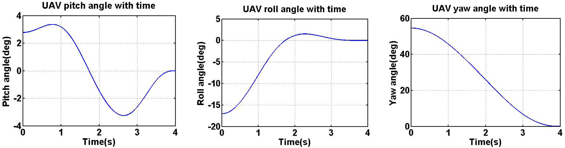
The attitude of the UAV during movement
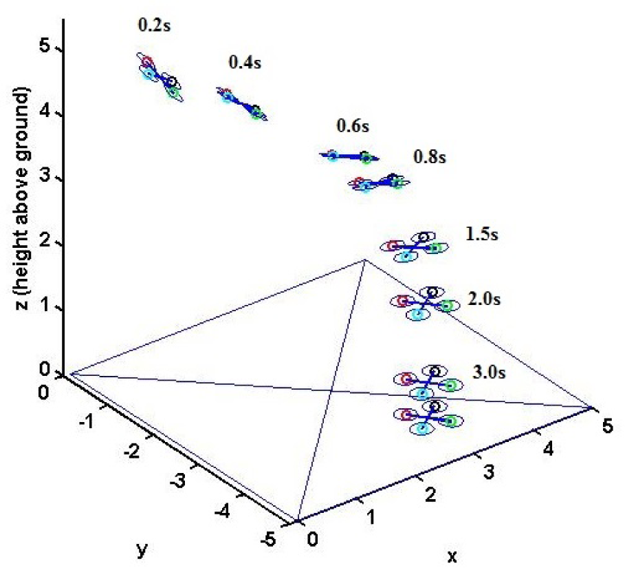
Snapshots of the flying UAV for several time instants (t=0.2 s, 0.4 s, 0.6 s, 0.8 s, 1.5 s, 2.0 s, 3.0 s)

Perching trajectory (left) and UAV kinematics (right)
4.2 Perching from a hovering state
We discussed the trajectory generation of a UAV starting from a flight state in Subsection 4.1, but a rotary-wing UAV can commence perching from a hovering state. In such a case, we need to use the strategy of intrinsic tau gravity guidance because the perching can be considered to start from rest (zero velocity).
As always, we assume that the time of the motion starts at 0 and ends at td. From equation (12), we can get the distance gap from the start to the end of the perching trajectory as follows:

where kd,g is a constant which can be determined by the solution of using the strategy of intrinsic tau gravity guidance.
Because the UAV flies directly to the target in this case, we can get the

Perching trajectory: 3D path (left) and some other motion variables (right)
As before, from the kinematics model presented in Section 3, we can obtain the attitude of the UAV. As shown in Figure 21, we can see that the trajectory of the pitch angle and the thrusts have the same problem as discussed in the perching from a flight state scenario. We can see that the thrust difference between Rotor 1 and Rotor 3 is large at the end of the movement from Figure 22. This also leads the UAV to an unstable state. As with equation (6), only k could be set among the parameters in equation (12). We will try to change the k value below.

Pitch angles of the UAV during movement

Thrusts of rotors (left) and the thrust difference of Rotor 1 and Rotor 3 (F1−F3) (right)
We present simulations with four different k values (namely, 0.1, 0.2, 0.3 and 0.4) which can meet our goal in the analysis in Section 2. The results are shown on Figure 23. We can also see that a k value nearer to zero is better than one nearer to 0.5. Unlike the perching from a flight state scenario, the flight time is decided initially and it does not change with the k value. Here, we know that the UAV's attitude is related to the k value. However, it remains the case that we still do not know the biological meaning of the relationship between the k value and the attitude of the UAV.
Pitch angles of the UAV (left) and the thrusts of Rotor 1 (right)
4.2.1 Tau coupling from a hovering state
Using equation (12), we can calculate the angular gap in terms of time t as follows:
where kα,g is a constant which can be determined based on the strategy of intrinsic tau gravity-guidance discussed in Section 2.
Using equation (28), we can get the
Perching trajectory (left) and gaps (right) for the coupling case
UAV velocity value and acceleration value for the coupling case

Pitch angles of the UAV during movement
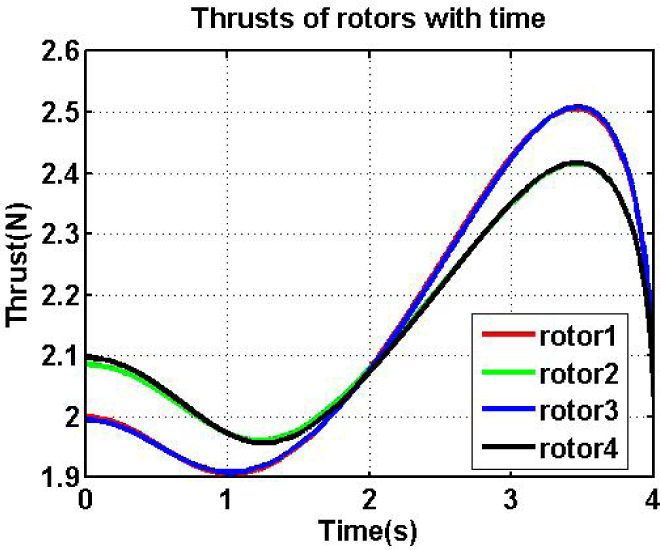
Using the dynamics model, the pitch angle of the UAV can be calculated as shown in Figure 26. We can see that it becomes zero smoothly at the end. The result of the thrusts of the rotors (Figure 27) shows that the UAV is stable constantly throughout movement.

Thrusts of four rotors (left) and the difference between the Rotor 1 and Rotor 3 thrusts (T1−T3) (right)
4.2.2 A full 3D case for perching from a hovering state
To observe the attitude performance of the UAV, a 3D case is provided. As before, the angular gap β(t) is added to the tau coupling case. We can calculate the angular gap in terms of time t as follows:

where kd,β is a constant ratio of the distance gap over the angular gap.
Using equation (25), we can get the
Perching trajectory (left) and gaps (right) for the 3D case
UAV velocity value and acceleration value for the 3D case
The attitude of the UAV during movement

Snapshots of the flying UAV at several time instants (t=0.5 s, 1.0 s, 1.5 s, 2.0 s, 2.5 s, 3.0 s, 3.5 s, 4.0 s)
Perching trajectory (left) and UAV kinematics (right)
5. Conclusion and Discussion
A bio-inspired trajectory generation approach for UAV/MAV perching (defined as the final approach for landing in this paper) was presented. The approach was based on tau theory, which was developed by biologists by observing and studying the behaviour of birds and certain other animals, including humans, when they approach an object for perching or capturing. We applied this bio-inspired approach to the perching problem of a rotary UAV and derived three different trajectory planning strategies, namely the tau in the action gap strategy, the tau coupling strategy, and the intrinsic tau gravity strategy. With these strategies, flight trajectory generation examples with a quadrotor were presented. Simulation-based kinematics and dynamics analyses of the vehicle for these perching examples were presented in order to demonstrate the performance of the approach.
Our study revealed that the parameter k is critical to the performance of the proposed methodology. We found that the UAV attitude is related to the k value and that a k value nearer to zero is more feasible than one nearer to 0.5 if all other conditions remain the same. Our study also found that, in a scenario involving perching from a flight state, keeping the k value close to zero while employing a tau coupling strategy can keep the system stable in perching flight. However, based on the analysis in Section 4, and considering the perching task as a physical contact task, using tau coupling is recommended.
It should be pointed out that the initially expected attitude of the UAV varies with the assumed k value when using the proposed strategies. This is caused by the fact that the initial acceleration of the UAV is nonzero according to equation (6). Hence, when we apply the trajectory generated by this method, we must adjust the UAV's attitude initially before the flight. Actually, in nature, birds also adjust their attitude first and then commence approaching or perching upon their target [34]. In fact, the expected initial attitude can be calculated from the inverse dynamics of the UAV with the known initial motion state and the required initial acceleration information. We will develop this initial attitude determination in our future work. In addition, we will add feedback control to the UAV perching control strategy in our future work in order to develop a complete perching control system for our flight experiment.
Footnotes
6. Acknowledgments
Dr. Zhen Zhang acknowledges the support of the Shanghai University and Shanghai Municipal Education Commission for his sabbatical research work at New Mexico State University.