
Abstract
With the development of bionic engineering, research into bionic robots has become a popular topic. In this field, the design of robotic mechanisms to realize the locomotion of insects forms a significant research branch. The current paper presents a caterpillar robotic mechanism that is composed of our newly-developed self-assembly modular robots (Sambot). A trapezoidal wave locomotion gait is planned for the caterpillar mechanism and the kinematics equations are established and solved analytically for such locomotion. The variations of the kinematics quantities are illustrated and discussed. The variation of the jump of the angular acceleration indicates that it is better to apply the trapezoidal wave gait to low velocity situations. Finally, the obtained data of the kinematics quantities is used to perform the gait control locomotion experiment and the errors of the experimental data are analysed in depth.
1. Introduction
Research into bionic robots has formed an active field of robotics in recent years. A number of robotic mechanisms have been designed to simulate the locomotion of insects or animals [1] and the locomotion gaits of these robots have also been widely investigated. Akinfiev and Armada [2] presented a climbing robot with non-rigid legs and analysed the influence of gravity on trajectory planning. Mezoff et al. [3] studied the biomechanical and neural control of hydrostatic limb movements in manduca sexta. Rhodri and Julian [4] analysed the characteristics of the passive and active rolling movements of natural living things and then gave a complete review of the design principles for rolling robots. Chen et al. [5] performed hydrodynamic analysis and simulation on a swimming bionic robotfish Spenko et al. [6] designed a hexapedal robot and studied its bionic climbing locomotion. Wang et al. [7] combined two typical kinematics gaits to realize the crawling motion of the inchworm and the tobacco hornworm in robots. Bayraktaroglu [8] investigated the snake-like locomotion of a biologically inspired wheel-less snake robot.
In bionic engineering, modular self-reconfigurable robots have wide applications because they can change their morphology through self-reconfiguration and then self-adapt to different and even unknown environments or undertake a wide range of different tasks. For example, a modular self-reconfigurable robot system could change into a worm-like shape when it has to go through a narrow tunnel; it could become a multi-legged structure if it has to walk over rubble; it could enhance its movement speed on flat ground simply by forming a ball-like or wheel-like object [9]. The advantages of such robot systems are that they are versatile, robust and low-cost. Due to these advantages, the past three decades has seen the rapid development of modular self-reconfigurable robots. Up until now, a variety of modular robots have been designed, such as ACM [1], CEBOT [10], Polypod[11], Tetrobot [12], Fracta [13], TeleCube [14], I-Cube [15], Fractum [16], Semicylindrical [17], Proteo [18], Crystalline [19], MTRAN [20], PolyBot [21], SMC Rover [22], Conro [23], Atron [24], Swarm-bot [25], Catom [26], Miniature [27], Microunit [28], Stochastic [29], Metamorphic [30], Molecubes [31], SuperBot [32], YaMoR [33], Miche [34], CKBot [35], ModRED [36], SMORES [37], HitMSR II [38], etc. According to the different geometrical arrangements of the robotic modules, the architectures of modular self-reconfigurable robot systems can be classified into three kinds: lattice [30], chain [21] and hybrid [20]. By considering the different modes of self-reconfiguration, they can also be categorized as: deterministic [12] and stochastic [29]. Based upon the alternative designs of the robotic modules, they can then be divided into two types: homogeneous [10] and heterogeneous [15].
Among the widely-studied living things involved in bionic robots, caterpillars are typical insects representing good values for robotic design. An understanding of the kinematics of caterpillars can provide important references for the bionic design of pertinent robots. Berrigan and Pepin [39] described the kinematics and allometry of limbless locomotion in four species of diptera. Brackenbury [40] presented a detailed characterization of the locomotion gaits in the pleuroptya caterpillar and also studied the locomotion modes for the larvae and pupae of chironomus plumosus [41]. Trimmer and Issberner [42] used three-dimensional kinematics to characterize the abdominal movements of soft-bodied, legged locomotion in manduca sexta larvae. Litvintsev [43] deduced the kinematics and dynamics equations of a caterpillar-bending homogeneous and continuous body. Li et al. [44] investigated the caterpillar-like locomotive pattern in nature systematically and then presented a novel mechanism to implement caterpillar-like locomotion with the gait generated by an asymmetric oscillation.
The current paper presents a caterpillar mechanism composed of the self-assembly modular robots (Sambot) developed by the authors [45–47, 53, 54]. A form of gait planning is put forth to characterize the trapezoidal wave locomotion of the robotic mechanism. Kinematics equations are established and solved for such locomotion, yielding the necessary computational data for gait control. Experiments are performed on the self-assembly process and the trapezoidal wave locomotion, which verify the present design and kinematics analysis.
2. Motion planning
2.1 Gait design
A caterpillar robotic system can be simplified as a planar linkage mechanism consisting of a series of links and the intermediate revolute joints. Generally, there are two kinds of locomotion modes for caterpillar robots. One is the horizontal mode on the ground [48] and the other is the vertical mode in the vertical plane [49]. The latter mode has more advantages than the former. For example, in vertical locomotion, the robot can go through narrow zones because it occupies space on the ground as narrow as its body section. Moreover, a robot moving in the vertical mode has higher obstacle-crossing ability, because it can climb over a barrier on the ground. In the vertical mode, the caterpillar robots can move with different wavelike locomotion, such as a triangular wave, a trapezoidal wave and other polygonal waves. The present paper only studies the vertical trapezoidal wave locomotion of the caterpillar robotic system.
Practical caterpillar robots may be multi-link mechanisms. For simplicity, we only take a five-link caterpillar robot as an example to illustrate the vertical trapezoidal wave locomotion. Figure 1 shows a complete cycle of such locomotion where the step length is d and the base angle of the trapezoid is φ0. The two ends of the mechanism are denoted by A and F, respectively. B, C, D and E stand for the revolute joints. The five links are represented by ①, ②, ③, ④ and ⑤. A movement cycle is composed of seven states - i.e., (a), (b), …, (g) - among which state (g) has the same shape as that of state (a) but moves a step length forward.
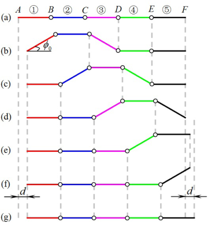
The process of a movement cycle (d: step length; φ0: base angle)
2.2 Superiority of the trapezoidal wave
As mentioned above, there may be several different wavelike locomotion gaits (triangular, trapezoidal, quadrilateral, etc.) for the present five-link caterpillar robot. To some extent, the waveforms determine a degree of locomotion performance in some respects, such as obstacle climbing and movement speed, etc. [50–51]. A wave gait including more joints in one wave period - such as a trapezoidal wave – allows the robot to move a greater distance or climb wider obstacles in one wave period than with a triangular wave. Comparatively speaking, the trapezoidal wave has superiority over other waves for two reasons: (1) it is more stable than the quadrilateral wave; (2) its obstacle-crossing ability is higher than that of the triangular wave. In order to obtain a stable wavelike locomotion, the caterpillar robot must have at least one module remaining static on the ground to provide the frictional force required by the locomotion. During the movement process, the more modules that are kept static on the ground, the more stable is the wave locomotion that can be achieved. It follows from Fig. 2 that for the present five-link robot the quadrilateral wave is the least stable. For a caterpillar robot, the obstacle-crossing ability is an important design objective, which mainly relies on two factors, namely the width and height of the wave. Generally, a wave with a larger width and height has greater obstacle-crossing ability. It follows from Fig. 2 that the triangular wave has the smallest width, which reduces its obstacle-crossing ability. Therefore, the trapezoidal wave is a relatively suitable locomotion gait for the present five-link robot in considering both stability and obstacle-crossing capability.

Three different wavelike locomotion gaits
3. Kinematics analysis
3.1 Kinematics model
It deserves note that in the transition process from state (b) to state (c), the positions of points A and E remain unchanged. Similarly, when the state varies from (c) to (d), points B and F are also fixed. It is obvious that there is a “shifting” action pattern among the links [52] - i.e., the action performed by link m at state j is the action to be performed by the next link at state j + 1. The vertical trapezoidal wave locomotion gait of a CONRO snake robot was addressed by Shen et al. [52], but the kinematics problem of such locomotion remains unexplored. The vertical trapezoidal wave locomotion is analysed in this section and then implemented by using our newly developed self-assembly modular robot (Sambot) in the next section.
For convenience of description, let us call the process from state (b) to state (c) a ‘movement unit’. Naturally, the process from state (c) to state (d) is also another movement unit. In Fig. 1, any one of the other subsequent processes between two neighbouring states is only part of a movement unit. Therefore, for the sake of gait control, we need to analyse a complete movement unit. As an example, let us consider here the process from state (b) to state (c). In this movement unit, points A and E are two fixed points. Therefore, the four pertinent links (i.e., ① ②, ③ and ④) and the ground form a closed chain mechanism, as shown in Fig. 3. In order to realize the gait control of the trapezoidal wave locomotion, we need to make clear the relations of the kinematics quantities between the four links. Since the mechanism has two degrees of freedom, if we assume that the first and last links of the mechanism in Fig. 3 have the same angular velocity, we can derive an analytical solution for the problem. As such, the kinematics quantities of the two intermediate links may be determined, which provides the theoretical basis and data for the gait control.

The intermediate process between states (b) and (c)
3.2 Constraint equations
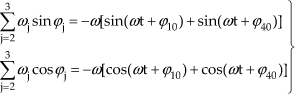
As stated above, the first and the last links in Fig. 3 are simultaneously driven by their motors at the same constant angular velocity ω. Their rotation angles are:

where the subscripts 1 and 4 stand for the quantities of the first and the last links in Fig.3, t denotes time, and φ10 and φ40 are the initial phase angles.
Assume that φ0 is the limit value of the base angle of the trapezoid (see Fig. 1). Then, referring to states (b) and (c) in Fig. 1, one arrives at:
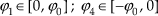

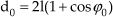
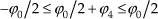
where l is the link length and d0 is the distance between the two fixed points in Fig. 3. In addition, φ0 is confined as being always less than π/2 in this paper.
The angular displacement constraint equations of the closed chain mechanism in Fig. 3 are:

where φj (j =1, 2, 3, 4) are the rotation angles of the four links, the anticlockwise rotation angle is positive and the clockwise rotation angle is negative.
Substituting Eq. (1) into Eq. (5) yields:
where f(t) and g(t) are two functions defined by:

Differentiating Eq. (6) gives the angular velocity constraint equations:
where ω2 and ω3 are the angular velocities of the two intermediate links in Fig. 3.
Again, differentiating Eq. (8), one obtains the angular acceleration constraint equations:
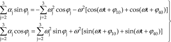
where α2 and α3 are the angular accelerations of the two intermediate links in Fig. 3.
Next, we first develop the analytical solutions to the above constraint equations and then present some computational results of the kinematics quantities.
3.3 Analytical solutions
Squaring the two equations in Eq. (6) and adding the results together, one obtains:

Consider the following identities:

where τ2 = tan(φ2/2).
Then, Eq. (10) can be transformed into a quadratic equation:
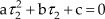
where a, b and c are functions of time given by:


It follows from Eqs. (7) and (13) that f(t) and a(t) are always positive. Moreover, from Eqs. (1) and (3), one can get the following relation:

Substituting Eq. (7) into Eq. (15) and considering Eq. (16) leads to:

It is found from Eq. (2) that:
Then, one may easily infer from Eqs. (17) and (18) that:

We define φ2 as being always less than π/2. Then, the value of τ2 is positive and the solution of Eq. (12) takes the form:

Then, the solution of φ2 may be obtained from:

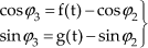
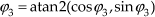
Putting Eq. (21) into Eq. (6) gives the values of cosφ3 and sin φ3, and then the value of φ3 can be uniquely determined by:
Finally, the angular velocities and angular accelerations of the two intermediate links can be obtained from Eqs. (8) and (9), respectively.


where p(t) and q(t) are two functions of time having the form:

3.4 Computational results
Illustrated in Figs. 4–6 are the variations of the kinematics quantities of links ② and ③ in the process from state (b) to state (d), including two successive movement units. In the computation, φ0 = π/6 and ω = –π/12 rad / s, which means that every movement unit costs 2 seconds. Therefore, the time interval 0s ≤ t ≤ 2s corresponds to the process from state (b) to state (c), and 2s ≤ t ≤ 4s to the process from state (c) to state (d).

The variation of φ2 and φ3 versus time (φ0 = π/6; ω = –π/12 rad / s)
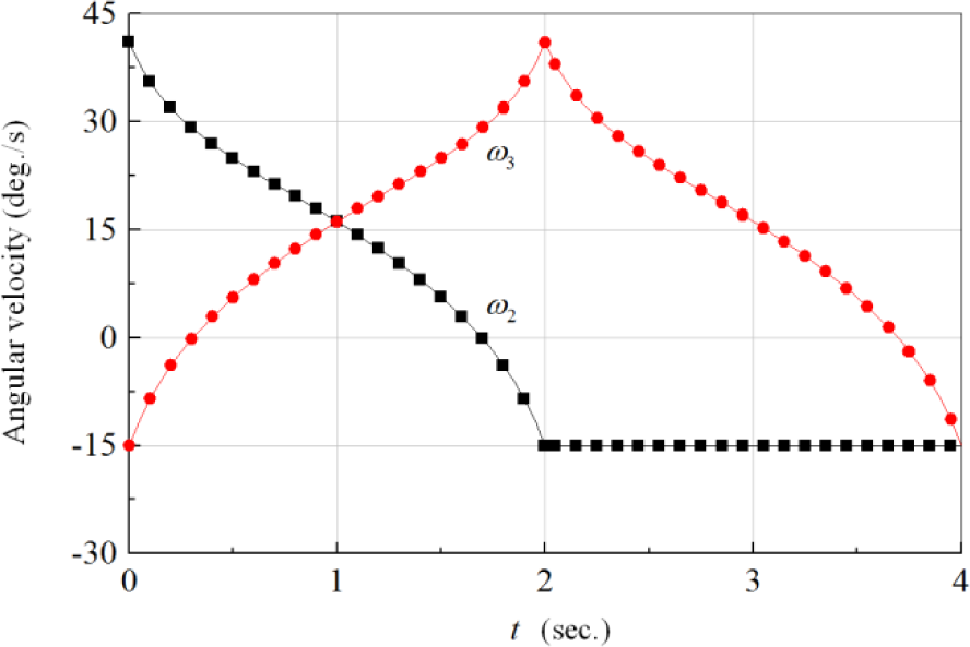
The variation of ω2 and ω3 versus time (φ0 = π/6; ω = –π/12 rad / s)

The variation of α2 and α3 versus time (φ0 = π/6; ω = –π/12 rad / s)
Figure 4 indicates that in the first movement unit the rotation angle φ2 has a maximum value larger than φ0. This is due to the fact that although links ① and ④ have a constant angular velocity, the angular acceleration of link ② is non-zero in the first movement unit (See Fig. 6). The variation characteristic of φ3 in Fig. 4 can also be explained in a similar manner.
It is found in Fig. 5 that at the transition point (i.e., t = 2s) between the two movement units, the angular velocities of the two intermediate links are continuous. This guarantees the natural transition between two neighbouring movement units.
However, Fig. 6 shows that the angular accelerations of the two intermediate links have a jump at such a transition point. The acceleration jump may produce inertial impact on the direct current motor. In order to find a way to reduce the impact, it is necessary to perform parametric sensitivity analysis. For convenience of description, we here use δ2 and δ3 to denote the acceleration jumps corresponding to the two intermediate links, which are defined as below:

where t0 = |φ0/ω is the transition point in time.
Illustrated in Figs. 7 and 8 are the variations of δ2 and δ3 versus ω and φ0/π. Here, the minus sign of angular velocity only denotes its direction. It is shown that both a decrease of the absolute value of the angular velocity ω and an increase of the base angle φ0 of the trapezoidal wave can reduce the angular acceleration jump and thus reduce the abovementioned inertial impact. When φ0 is given, the inertial impact can be decreased by choosing a lower value of |ω|. In this sense, the trapezoidal wave gait is suitable for application in low velocity situations.
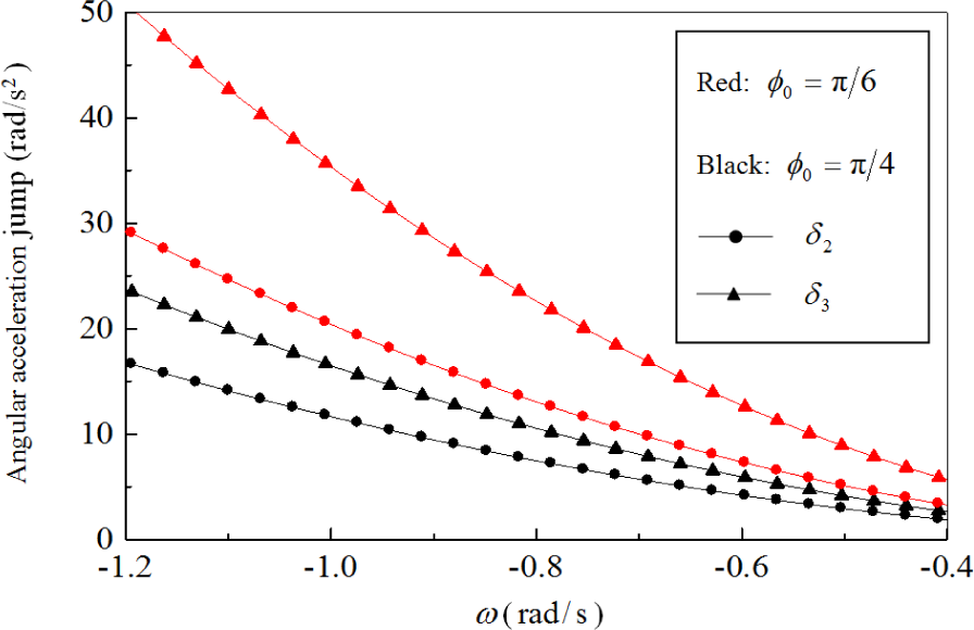
The variation of δ2 and δ3 versus ω

The variation of δ2 and δ3 versus φ0/π
4. Robotic caterpillar mechanism
In this section, we use our newly developed self-assembly modular robots (Sambot) to construct the caterpillar robotic mechanism [45–47]. As shown in Fig. 9a, a Sambot is composed of a cubic main body and an active docking interface. Each of the four laterals of the main body can act as a passive docking interface. The active docking interface can rotate around the central axis of the main body to dock with a passive docking interface of another Sambot (see Fig. 9b). There are two wheels on the bottom of the main body. Thus, every Sambot has the capability of autonomous locomotion. A number of Sambots can move to self-assembly into a robotic mechanism such as the five-modular caterpillar shown in Fig. 10. Each Sambot has 16 pairs of infrared sensors (IRs) to detect the target and guide the self-assembly process: eight pairs of approaching IRs, four pairs of detecting IRs and four pairs of docking IRs. Three direct current motors installed in the main body are used to drive the rotation axis and the two wheels, respectively. A battery in the main body provides power to the motors and sensors.

The structure of Sambot

A five-modular caterpillar robotic mechanism
As shown in Fig. 11, each Sambot is equivalent to a two-link mechanism. The circle stands for the rotation centre, which is in fact the central axis of the main body. The white link represents half of the main body and its length is 40 mm. The black link denotes the active docking interface and its length is 62 mm. As such, the robotic caterpillar in Fig. 10 is equivalent to the linkage mechanism in Fig. 12. For the present kinematics problem, the head and the tail of the caterpillar mechanism can be ignored. Accordingly, the equivalent linkage mechanism is simplified as a four-link mechanism as shown in Fig. 13.

The Sambot and its equivalent mechanism

The equivalent linkage mechanism of the five-modular caterpillar

The simplified equivalent linkage mechanism
5. Locomotion experiments
5.1 Experimental method
Before the trapezoidal wave locomotion experiment, a Sambot is fixed as the seed and four other Sambots are scattered on the platform to automatically execute the docking task and then successfully self-assemble into a caterpillar robotic mechanism. After the caterpillar mechanism has been formed by the self-assembly of Sambots, the kinematics quantities derived and calculated in section 3 are used to perform the trapezoidal wave locomotion. In the locomotion experiment, the base angle of the trapezoid is chosen as φ0 = π/6 and the angular velocity ω is given a low value of 0.1π rad/s. To limit the rotational range, the method of angular displacement-based control is used to trigger the braking of the joint motors in a timely fashion. The angular displacement-based control is a PID method to limit the rotational range of a robotic joint through the angular displacement feedback of the DC motor. Because every Sambot module acts as a joint of the caterpillar, the PID method can be used to control the angular displacement of such joints. When the target value of the angular displacement in a time interval is prescribed for a joint, the associated DC motor can achieve the closed-loop control of the angular displacement automatically.
The video tracking system shown in Fig. 14 is used to record the locomotion process and measure the angular displacement of every joint. A series of snapshots of the trapezoidal wave locomotion are taken from the video and shown in Fig. 15, which verifies that the trapezoidal wave gait can be employed to control the locomotion of the caterpillar robot in low-velocity situations successfully. The locomotion video is provided as an attachment to this paper.

Video tracking system

Snapshots of the trapezoidal wave locomotion
5.2 Data of swing angles
The variation data of the swing angles of the links versus time is shown in Fig. 16, which is obtained by the video tracking of the locomotion process. From the 5th second to the 9th second, the swing angle curves corresponding to links ② and ③ in Fig. 16 are in agreement with their theoretical curves in Fig. 4. However, it should be noted that the time consumption during the experiments is different from that of the theoretical results, and such a delay is probably caused by the friction in the locomotion. In addition, it is found that the maximum swing angles of the links ③ and ④ are larger than their theoretical values, and the curves in Fig. 16 are not always consistent with the theoretical results. These differences may come from the errors of the displacement feedback control of the motors and the video tracking.

The swing angles of the links
5.2 Data for joint displacements
Shown in Figs. 17 and 18 are the vertical and horizontal displacements of the joints measured by video tracking. According to the theoretical model, the maximum values of the vertical and horizontal displacements of a joint can be calculated as follows:
The maximum vertical displacement:
102 × sin π/6 = 51mm;
The maximum horizontal displacement:
2 × 102 × (1-cos π/6) = 27.33mm.
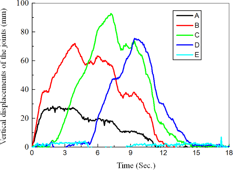
Vertical displacements of the joints
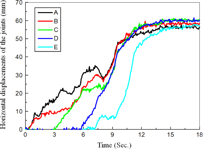
Horizontal displacements of the joints
However, it is seen in Figs. 17 and 18 that the errors of these maximum values are large. By substituting the measured maximum values into the theoretical model, it is found that the maximum swing angle is about π/4, which deviates from its theoretical value π/6. Such a deviation can also be seen from the snapshots in Fig. 15. The error of the maximum swing angle is mainly caused by two factors, one being the displacement feedback control of the joint motor and the other being the test method of video tracking.
5.3 Data of distance between joints A and E
In the theoretical derivation, it is assumed that A and E are two fixed points. In order to verify the correctness of this assumption, the distance between A and E in a movement unit is obtained by the video tracking of the locomotion process and shown in Fig. 19. It is found that the variation of the distance between A and E is negligible as compared with the distance itself - that is to say, the sliding in the real robot experiments can be ignored. Therefore, the theoretical assumption is acceptable.

Variation of the distance between A and E vs. time
6. Conclusions
A trapezoidal wave locomotion gait is presented for a caterpillar robotic mechanism formed by the self-assembly of modular robots (Sambot). Kinematics equations are then established and solved for the caterpillar locomotion. The computational results are illustrated to show the variations of the kinematics quantities. Parametric studies on the jump of the angular acceleration lead to the suggestion that the trapezoidal wave gait should be applied in low velocity situations. The obtained data of kinematics quantities are used to control the practical locomotion. Experiments on the trapezoidal wave locomotion are performed, the data of the kinematics quantities are provided and their errors are analysed. The error analysis reveals that both the displacement feedback control of the joint motors and the video tracking-based test method should be improved in future work. Finally, it deserves note that the present paper only studies locomotion on an indoor plain floor. Next, locomotion experiments should be performed in different outdoor terrains to get more practical results.
Footnotes
7. Acknowledgements
This work was supported by the National High Technology Research and Development Programme of China (“863” Program) (2012AA041402), the National Natural Science Foundation of China (Grant No. 61175079 and No. 51105012) and the Fundamental Research Funds for the Central Universities (Grant No. YWF-11-02-215).