
Abstract
This paper describes a device server for a miniature mobile robot. Generally, miniature robots have low-size memory and relatively slow microcontroller to realize complicated tasks. Therefore, a device server for small sized mobile robots is proposed with the intention of increasing their capabilities. The proposed software system runs on the microcontroller of the robot, and serves a collection of sensors and actuators over serial rf transceiver to authorized clients. The system has modularity and multi-tasking capability. The proposed system is implemented on a Z-80 microprocessor-controlled mobile robot. It is shown that proposed system is capable of serving one client and two processes.
Introduction
The leading technology makes sensors smaller, so that, miniature robots may contain plenty of them. Consequently, this may increase their capabilities at most as much as their big-sized complicated fellows. On the other hand, data taken from different types of sensors should be processed quickly in reactive manner. The low-cost microcontrollers are far to fulfil these requirements unless they are supported by relatively fast microcontroller systems. Additionally, it is hard to develop applications for mobile robots using assembly codes. These difficulties motivated us to develop a software architecture to increase robot's capabilities and making application development easier.
Several device servers have been implemented for mobile robots for different purposes. For instance, Player, which is a robot device server for distributed control, provides a networked interface to a collection of robot device drivers (Gerkey, 2001). It connects the sensors and actuators of the robot to clients over TCP/IP sockets. Similarly, COLBERT/Saphira architecture provides a server program running on the pioneer robots (Konolige, 1997). These tools were developed in order to write control programs of mobile robots easily. In addition, device server systems are developed for the purpose of teleoperating micro-robots. For example, a teleoperator system designed for the eyebot micro-robot has a server program running on the robot (García-Morata, 2003). It sends the sensor readings and drives the actuators according to the commands received from client-side operator.
We have developed a small mobile robot (Junior) in our laboratory. This robot uses a Z-80 microprocessor as a control unit. We are planning to use this robot as a member of a heterogeneous mobile robot team. We will assign tasks to the team, which will require heavy computer processing and large memory sizes (i.e. map making). Since the capacity of the Z-80 is not adequate to handle this kind of task, we plan to use Junior only to collect information about the environment using its sensors. The collected data will be transferred to a remote pc through rf communication, data processing will be done on the pc and the resulting commands send back to control the robot. To accomplish this we developed a device server.
The proposed system was inspired by the traditional multi-tasking operating systems. Sensor reading, serial communication and user-defined processes are considered separate tasks which are waiting for their processing turn. A CPU scheduling module assigns the waiting tasks to the microcontroller using an appropriate scheduling algorithm. Thus, the processor does not wait for the sensing processes during the time between firing and reading. This improves the performance of the overall system. Additionally, the proposed system improves the modularity of the system, because adding a new sensor and its driver program to the system is easier by the proposed structure.
The remaining of the paper is organized as follows. In section 2, the proposed architecture is explained in details. Section 3 introduces the small robot (Junior) developed at Eskisehir Osmangazi University. Applications of the proposed system are explained in section 4. Conclusion is given in section 5.
Architecture
The main purpose in developing the architecture is to use the microcontroller system on the robot to perform the commands received from clients. The system has two main blocks: kernel and processes. The overall system architecture is shown in Fig. 1. The kernel performs some port initializations, device checking, device initializations and CPU scheduling for processes. Processes would be device processes, user-defined processes, and server process. The device processes perform the tasks about sensors and actuators according to received commands, and returns the results if applicable. The user-defined processes are programs running on the robot to perform some specific tasks, for example, emergency stop when the robot hits an obstacle. The server process implements communication task and exchanges the commands of clients and responses of the devices. One of the most important features of the structure is that modifications on any process do not affect the others.

Overall system architecture
When the system is powered on, the first part executed is the kernel. It initializes the serial and parallel ports required for communication with the devices on the robot. Then, it checks the devices whether they are active or not. This part is necessary for a reliable performance of the system. Without checking, the system may try to reach inactive devices according to clients' request, and this may lead to faulty operation. Afterward, it lists the active devices in a table for initialization of the devices and scheduling process. Active devices are configured prior to sensor readings request or send command.
The most important part of the kernel is CPU scheduling. This part distributes the CPU usage to the waiting processes. A scheduling algorithm may be used to improve the performance of the robot. In this study, round-robin scheduling algorithm was chosen because of its easy implementation (Silberschatz, 1998). The algorithm holds a queue, which contains waiting processes. It lets CPU to perform the first process in the queue. Every waiting process is shifted by one. Then, as seen in Fig. 2, new and uncompleted processes are added at the end of the queue.

Scheduling algorithm
The CPU scheduling module gets the information about the processes using program control blocks (PCB). The PCB's are defined for each process. They are simply preformed registers and contain required data about the processes for being used by the CPU scheduling module and other processes. The format of a PCB is as follows:
Terminated: It defines the fact that the process has finished.
Ready: It defines the fact that the process is ready to be executed.
Waiting: It defines the fact that the process has interrupted, and it is waiting for a continuation signal.
Blocked: It defines the fact that the process is valid; however, it cannot be executed. For instance, there is a device driver program for electronic compass; however, the device either has not been installed or it is faulty.
There exist two types of processes: device processes and user-defined processes. The device processes take the commands from their own command buffers in PCBs. They run according to the commands, and then load the data to their own data buffers in the PCBs. The state of the process becomes ready while the command is loaded. Thus, the CPU scheduling module automatically adds this process to the queue for execution.
User-defined processes are slightly different than device processes. They implement the tasks not necessarily for serving to clients. For instance, a user-defined process may cause emergency stop when the robot hits any obstacle. The user-defined processes may also serve to clients. For instance, it can send information about the system, such as system errors, system configuration, etc. The server process provides the communication with clients. It is called by the device processes, but its internal structure is defined by the architecture. The main goal of the server process is to provide continuous communication between mobile robot and clients, which can be a PC, or any other mobile robot. A simple packet format is used for communicating with clients. There are two types of packet formats as given in Fig. 3.
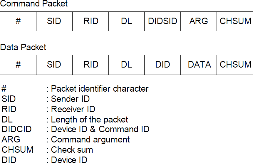
Communication packet formats
Both types of the packets start with a special character to eliminate the unwanted packets and determine the starting point of the packet. The second and third bytes contain sender id and receiver id, respectively. Since the system is designed for the mobile robot to be commanded by multiple clients, these identifiers are necessary. The length of the packet clarifies how many bytes are there on the remaining parts of the packet. This information is useful for implementation purposes. The following content of the packets have differences between command and data packets. The command packet includes device id and command id together which are codes assigned for every device and command, respectively. The argument of the command should be given, if applicable. The data packet contains only device id to identify the data producer, and data required by clients. There is a check sum at the end of both packets to check the correctness of the received packet. Clients send the command packets, and the mobile robot system sends data packets.
First, the server process listens to the serial port for a command. If the received command is valid, its checksum is determined to check the correctness of the command. Also, the receiver id is compared with the id of the mobile robot. Then, it loads the command with sender id into the command buffer of the related device process. Second, the server process sends the ready data to clients one by one. It looks at the data buffers of the processes listed in the table of active processes. If a data buffer is full, its data is send to the corresponding client.
The mobile robot system used for application of the proposed architecture is seen in Fig 4. The brain of the system is a Z-80 microprocessor-based control card. It has two serial and three parallel ports to manage the hardware of the mobile robot. A keyboard card with a display is used to execute and change the loaded program. The system has four wheels that are driven by two stepper motors. Like cars, the wheels in the back drive the mobile robot forward or backward. The ones in front are used to steer the mobile robot. Both stepper motors are connected to a stepper driver card. An infrared sensor array consisting of five Sharp GP2D02 infrared range sensors, which are placed, with intervals of 45°, is assembled in front of the mobile robot (GP2D02, 2003). IR sensors are connected to the control card through a parallel port. Also, a CMUCAM is located on the mobile robot (Rosenberg& Nourbakhsh, 2003). Connection between the control card and CMUCAM is over a serial port. An rf serial communication board allows clients to reach the robot system. Its frequency is 433Mhz., and is connected to the control card over serial port.
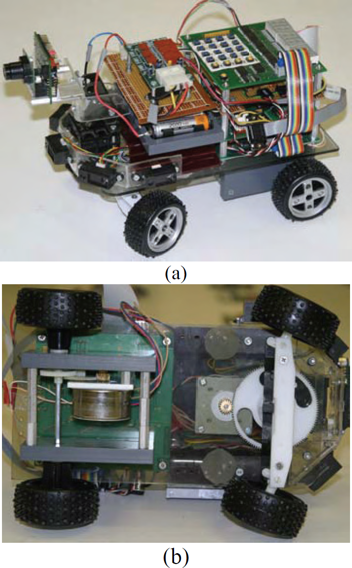
Sample robot system:(a)Top view,(b)Bottom view
Block diagram of the mobile robot system is shown in Fig.5. A 12-volt battery block supplies the required power for the whole system.
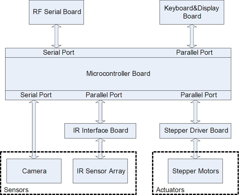
Block diagram of the mobile robot
The proposed system is tested to read range data taken by the IR sensors and drive the robot by the commands given from a remote PC. The command list used in the application is as follows:
Get distances Go forward Go backward Turn right Turn left Stop
Each command is represented by a unique code. ID numbers are assigned to the mobile robot system and PC, which is used as a client. On the PC side, a simple console-based program was developed to command the mobile robot system. Its flow diagram is given in Fig. 6. The CPU scheduling module manages the processes. Its flow diagram is given in Fig. 7. First, it checks the active processes. It lines up the processes with ready states in a queue. Then, the first process of the queue is executed. After the execution, the process is sent to active process list if it still is in the ready or waiting state. Finally, the CPU scheduling module shifts the queue and adds the ready and waiting processes in the updated active process list.

Flow diagram of the console-based client program
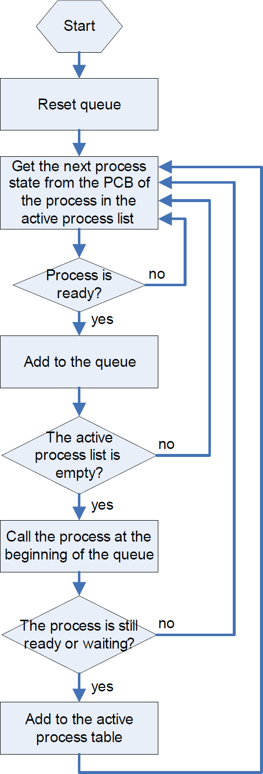
Flow diagram of the CPU scheduling process
State of the server process is always kept ready. The CPU scheduling module adds this process into the queue again after the execution of the process finished. As seen in Fig.8, the server process waits for command packets. When a packet is received, it is checked whether it is received in correct form and the receiver of the packet is correct. Then, the sender ID, command ID and command argument in the packet are stored into the command buffer of the related process. Then the data in the data buffer is sent to related client.
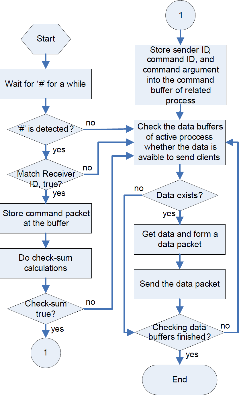
Flow diagram of the server process
Two device processes, reading IR sensors and driving stepper motors, are implemented. Flow diagrams of the processes are shown in Fig. 9 and 10, respectively.
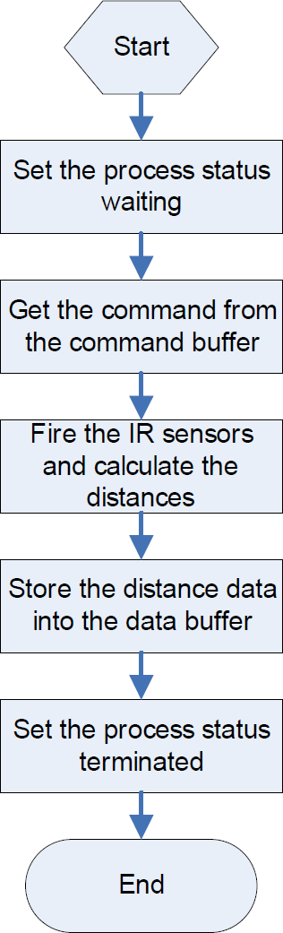
Flow diagram of the device process for IR sensor

Flow diagram of the device process for stepper control
After implementation of the proposed system, the commands were sent to the mobile robot system randomly. The mobile robot system moves according to stepper motor commands and sends the IR distance readings whenever required.
A device server architecture was developed for a miniature mobile robot. As a starting application, two processes were implemented. It is shown that the proposed architecture is successful in realizing these two processes. However, in order to increase the effectiveness of the mobile robot, new processes should be added and the system should be analyzed for its performance with additional processes.
The proposed system is applied through rf serial communication with a remote client. However, a PDA also can be used for the purpose of extending the computation capabilities of the miniature mobile robot. PDA as a single client can be connected directly to the serial port of the microprocessor board. Thus, the device server receives commands only from the PDA.
In addition, some scenarios may be implemented for the developed system. For instance, big-sized mobile robots can be clients for the miniature robot. As they search an environment, they can manage the miniature robots to map the places, which they cannot reach, like under the tables.
In the future, some other processes, especially for the devices on the robot, will be added to the system, and the system will be tested to see how it behaves when more than one client command the mobile robot.
Footnotes
Acknowledgement
This work has been partially supported by The Scientific Research Project Foundation of Eskisehir Osmangazi University with project #200315030.