
Abstract
There is a growing interest in applying intelligent technologies to assistant robots. These robots should have a number of characteristics such as autonomy, easy reconfiguration, robust perception systems and they should be oriented towards close interaction with humans.
In this paper we present an automatic hotel assistant system based on a series of mobile platforms that interact with guests and service personnel to help them in different tasks. These tasks include bringing small items to customers, showing them different points of interest in the hotel, accompanying the guests to their rooms and providing them with general information. Each robot can also autonomously handle some daily scheduled tasks. Apart from user-initiated and scheduled tasks, the robots can also perform tasks based on events triggered by the building's automation system (BAS). The robots and the BAS are connected to a central server via a local area network.
The system was developed with the Robotics Integrated Development Environment (RIDE) and was tested intensively in different environments.
1. Introduction
For a long time, service robots have been a science fiction vision of the future. Those robots were mostly intended as humanoid assistants, capable of helping people in different ways with sophisticated communication systems. The construction of that kind of versatile and robust robot is still far from reality. However, over the last few years a few successful examples of service robots have appeared on the market. A couple of examples are the cleaning robot Roomba [1] and the military robot PackBot [2]. As technology evolves, these kinds of robots are expected to grow in number. Some governments and companies are investing in service robot research as a response to an emerging aging population. Research has been mainly conducted on robots that provide support to humans in a variety of forms and fields. These forms of help include social interaction robots [3, 4], rehabilitation robotics [5, 6, 7], tour guide robots [8] delivery robots [9] and nurse robots [10].
The research presented here is oriented towards the construction of a hotel assistant system where robots would be able to execute tasks autonomously, such as guide guests to their rooms and other places in the hotel, provide hotel information to guests, or deliver small items to their rooms. Robots would need to be able to interact with some of the building's elements, such as elevators or automatic doors. In the proposed system all the devices in the building are connected to the local network over Ethernet using the Modbus fieldbus. A module in the central server controls all the actuators connected to Modbus according to the needs of the other modules and communicates changes in the sensors.
Tasks can be requested at any time and the system should be designed so that it assigns them to robots in an efficient way. In the proposed framework a process in the central server is tasked with allocating the resources needed for each task.
The rest of this paper is organized as follows: the next section introduces the system architecture and describes the main elements of the BAS; section 3 presents the robots used in this research; the main components of the robot control architecture are described in section 4. Robots will connect to the central server to share information with users, other robots and the building automation system using JIPC - this will be shown in section 5. Finally, section 6 presents the results and concludes the paper.
2. System architecture
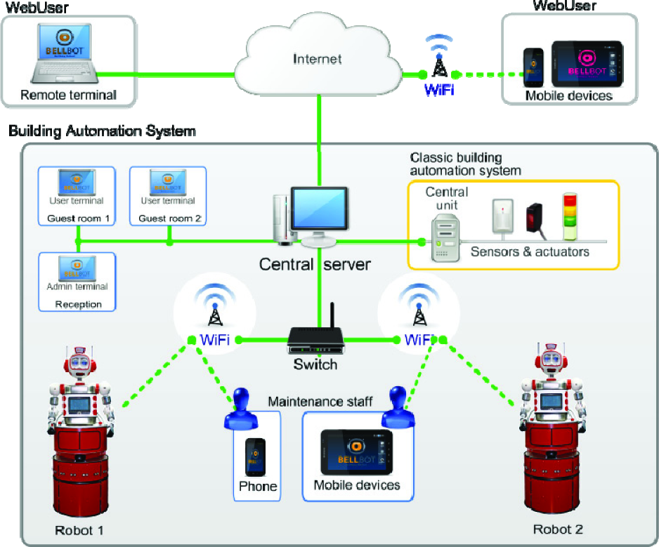
A potential scenario is depicted in Figure 1. Robots are integrated in the hotel building and connected to the central server via Wi-Fi. Users can request robot services from a terminal on their room or by interacting directly with the robot. From their rooms, guests can request small items such as newspapers or snacks. The central server will receive the request and it will decide which robot to send. Meanwhile, employees can monitor the system from any terminal connected to the local network or the internet.

Hotel assistant system scenario.
All the running GUIs and the BAS are also connected to the central server. Some of the elements controlled by the BAS which need to interact with the BellBot system include:
People transportation systems such as elevators and escalators. Robots request an elevator from the central server. This server interacts with the BAS to request the elevator, which in turn opens and closes the doors and moves it to the appropriate floor.
Automatic doors. In a similar way to elevators, robots can request that the BAS open a door via the central server.
Security systems: access to control devices, smoke detectors, etc., the Bellbot can also be used to check alarm situations. For example, if a smoke detector is activated, the robot can be sent to validate the alarm.
Event sensors. Different building sensors can automatically activate a robot task. For example, the activation of a sensor in the newspaper box can start the delivery of a newspaper task.
In our application we integrate the mobile robots as new elements of the BAS. The robots share information with other elements of the system through the central server:
Send information about their state (position, …) and sensor readings (laser, camera images, …).
Request other elements to execute some commands such as “open a door”.
Receive information about events such as “door opened” or BAS sensor activated.
Receive task execution requests.
The connections between different elements in the BAS are shown in Figure 2. The starting point is the classical BAS. Sensors and actuators positioned throughout the building are connected to the central unit that controls and monitors the edifice state.
Connections between the different elements of the architecture.
The classic BAS is connected to a computer (Central server) that registers all the events produced by the different sensors. In our case, all these devices are connected via Modbus using the building's local network (Ethernet).
In our approach, a set of autonomous mobile robots are also connected to the central server via Wi-Fi, GPRS or 3G.
Guest and maintenance staff can monitor the system using two different graphic user interfaces (GUIs).
Whilst robots are not performing any task, they should be connected to the charging stations located in a special room of the hotel. A typical task might start when one guest requests an item such as a soda can from the bar. In this case the guest should use the guest GUI in his or her room which is connected to the central server. In the central server a task manager will assign a task to a robot or will queue the task if all the robots are busy. Once the task is assigned, the robot will plan a route to the bar, navigate to the bar and then order the soda from the bartender. The order is also shown in the robot's touchscreen and the robot's belly-box doors (Figure 3) will open. Once the bartender sets the order in the belly-box, he or she must confirm having done so on the screen; then the robot will close the doors. The next step is to navigate to the guest room, ask the guest to take the soda and open the belly-box doors. After the guest receives the soda, he or she should confirm this on the touchscreen and the robot will close the belly-box doors. Finally, if there are pending tasks, the robot will start a new one, otherwise, it will return to the battery charging station.

Bellbot base.
3. The robots
We have designed a wheeled, friendly-looking prototype (Figures 3 and Figure 4). Using this design, we have built two units named

Bellbot body
The Uncanny Valley theory [11] states that as a robot is made more humanlike in its appearance and motion, the emotional response from a human being towards the robot will become increasingly positive and empathic. However, when the appearance is too close to that of humans but still obviously not human, there comes a point where the response quickly turns to that of strong repulsion. Conversely, as the appearance and motion continue to become less distinguishable from a human being, the emotional response becomes positive once more and empathy levels approach those of human-to-human interactions.
Some roboticists [12] have criticized the theory and other researchers [13] consider the uncanny Valley to be somewhat flawed. Even though these androids might look like humans, their motions are, so far, quite different.
Animated toy looking robots can be as expressive, or even more so, than androids and they are usually easier to control. Since our main interest is expressivity, we decided to build a robot with a simple toy-like appearance.
The robot base shown in Figure 3 contains all the navigation devices:
Two brushless Longway motors (80W/24V, 6.2N/m). One for translation and the other for rotation.
LiFePO4 26V/40Ah battery that provides power autonomy for 3 to 5 hours.
Bumpers. All the skin works as a bumper so that, if the robot hits any obstacle, it will be detected.
Sonar. It has a ring of 16 sonars whose measurements work by using the obstacle avoidance method (BCM) [18].
Hokuyo URG-04LX laser. Information provided by this laser is also used by the reactive control (BCM).
Sick LMS100/10000 laser. The readings obtained by this laser are for localization, obstacle avoidance, and map building purposes.
The robot body (Figure 4) includes most of the devices used for social interaction.
Most of the onboard devices, including the motors, servos, sonars, bumpers and touch sensors, are connected to a CAN bus using the RoboCAN protocol [14]. The control unit (mini-ITX VIA EPIA EN1200) constitutes the master module in RoboCAN and the slave modules are control cards with a PIC microcontroller.
The slave modules in this prototype are four control cards with corresponding PIC microcontrollers (Figure 5):

Bellbot control architecture
Module 1 is with a dsPIC30F4012. It includes a predictive PID controller to control the velocity of one of the motors. It also uses information from the encoder. This module includes a few bumpers and it publishes a CAN frame when a bumper is activated.
Module 2 is with a dsPIC30F4012. It is very similar to module 1 and controls the velocity of the other motor.
Module 3 is with a PIC18F258 and controls half of the sonar sensors and some bumpers.
Module 4 is a copy of module 3 with a PIC18F258 that controls the other half of the sonar sensors and some bumpers.
Module 5 is with a dsPIC30F4011 and it controls all the servomotors of the body and sensors, including the touch sensors and other digital inputs.
Besides the devices connected to RoboCAN, the robot includes:
The Sick laser, connected to a RS232 port.
The Hokuyo laser, connected to a USB bus.
The camera, located in one eye, connected to a PCI frame grabber, installed on the mini-ITX board.
The speakers and microphone with corresponding sockets on the mini-ITX board.
4. Robot control architecture
The on-board mini-ITX PC runs on Linux OS and we use a modular architecture developed with RIDE (Robotics Integrated Development Environment) [14] to control the different robot devices, navigate the robot, connect to Wi-Fi and perform the robot's different tasks. The structure of this modular control architecture is shown in Figure 5. Even though the different modules are organized into four sets, they can be mapped using the three layer architecture popularized by Bonasso et al. [15].
The hardware servers and control sets implement the functional layer while the RoboGraph dispatch implements the executive and planning layer [14]. Finally, it includes a set of processes with which it can interact with users and connect to other processes for multi-robot applications.
Certain navigation modules are imported from CARMEN [16], such as localize, navigator and the Pioneer base hardware servers. Unlike CARMEN, however, motion control is divided into high-level (strategic) planning [17] and lower-level (tactical) collision avoidance using the BCM method [18]. CARMEN integrates obstacles from the map into its workings and plans a new trajectory accordingly, in order to avoid obstacles. Integrating all but the lowest-level motor control into a single module can produce optimal plans. However, due to the lack of precision in the localization system, the obstacle integration process can narrow some openings in the map. When the opening is only a little bit wider than the robot diameter, this difference can lead path planning to discard a possible path through that opening. We observed this behaviour with CARMEN in our office environment on several occasions, when the robot had to go through very narrow doors and corridors. To avoid this problem, in our system, obstacles are not included in the map and are avoided using BCM.
Each module in Figure 5 is a Linux process that exchanges information with other modules using Inter Process Communication (IPC) [19]. Developed at Carnegie Mellon's Robotics Institute, IPC provides a publication-subscription model whereby processes can pass messages to each other via a central server process. Each application registers with the central server and specifies the types of messages it publishes and the types it listens for. Any message passed to the central server is immediately copied to all other subscribed processes.
4.1 Hardware server modules
The hardware server modules govern hardware interaction, providing an abstract set of actuator and sensor interfaces and isolating the control methods from the hardware details. Some of these devices, such as the laser and sonar, are used in navigation for obstacle avoidance using the BCM method [18]. The low-level control loops for rotation and translation velocities are implemented in the CAN slaves that control the motors.
The hardware server's layer provides an effective decoupling between the hardware and software control modules. Therefore, changes in hardware components can be made without the need to change the modules for the higher layers.
4.2 Control modules
The control modules integrate sensor and motion information to provide improved sensor odometry, basic navigation capabilities (localization, path planning and follow path) and basic application-specific functions (say text, play sound, move hands, etc).
This layer deals with the main problems in robot navigation (obstacle avoidance, localization, mapping and path planning). The maps are constructed using a scan matching algorithm [20]. A path planner finds the best route in these maps to reach the different navigable points in the environment using Konolige's local gradient descent planner [21]. The environment in this application is dynamic and the robot might encounter some obstacles that were not present when the map was created. For example, it might encounter obstacles that can change positions (chairs, tables, etc.) or moving obstacles such as people. Robots are able to avoid such obstacles using the BCM reactive control method [18].
To deal with the localization problem, a particle filter [22] that uses information from the map, the laser range and the encoders are used. We have also worked on an IR tag alternative for open and populated environments [23].
The mobile robots we are using have onboard power supplies in the form of a Li-ion battery that last for a finite amount of time (for three to five hours). After that, the robot would require human intervention for extended usage. To achieve true long-term autonomy, we have developed a recharging mechanism which enables a robot to interrupt its regular operation, go to the charging station and start a docking sequence.
The charging mechanism consists of a new onboard Docker module that subscribes to a docking message. That message starts the docking mechanism. The charging station is passive (has no sensor) and is detected by the robot using navigation sensors, namely the laser. Therefore no additional sensors are needed.
4.3 Executive modules
The robotics development environment (RIDE [14]) includes a tool named RoboGraph that implements the executive layer (Figure 5), which consists of two modules: the GUI, used only for application development and the dispatch which runs when the robot is performing assistant operations.
RoboGraph GUI is the programming IDE which defines and debugs application tasks (Petri nets). Developers must build the Petri nets (PN) that coordinate the work of the rest of the modules, including some actions carried out by users on the different interfaces. We have decided to use Petri nets to model this behaviour because they have proven to be a good mechanism with which to model discrete event processes.
RoboGraph GUI can work in three different modes (editor, monitor and play logger) and it is possible to switch at any time to a different mode. In editor mode, the application programmer can create new tasks using a simple and intuitive Petri net graphical editor. In monitor mode every running Petri net is shown in a different tab with its current marking. When dispatch evolves a Petri net marking, an IPC message is issued and GUI will update the monitor tabs. Therefore, using this monitor mode, developers obtain a snapshot of the status of the system shown using the markings of the running Petri nets. Using a similar process, it is possible to play back the evolution of a finished run, loading a log file created by dispatch.
Robograph dispatch loads from an xml file and executes tasks defined as Petri nets. The modules that request the task executions are mainly the user interfaces (user requests a new task) and the dispatch itself in the case of a Petri net referenced inside another net. When executing a task (Petri net), this module schedules the different actions of the functional (basic actions), executive (other Petri nets) and interface layers (user and web interfaces), as well as synchronizing them with the events produced. Interaction with other modules in the architecture is carried out by publishing and subscribing to messages.
Therefore, problems in a module, such as a block, do not block the dispatch and we can set up simple mechanisms to detect and recover from a failure or exception situation.
The Petri net can evolve only with the arrival of IPC messages or with the expiry of a Timer. Dispatch publishes and stores IPC messages about its state for debugging purposes. Every time a change occurs in a Petri net status (start, stop or evolve) or in the waiting queues (new requests added or removed), a new IPC message is issued and stored. These messages are used by RoboGaph GUI when working in the monitor mode or the play logger mode to show the status of the different tasks.
4.4 Interface modules
There are several GUI modules that can be used by the programmer to debug and trace the control and hardware server modules. Additionally, one onboard interface module allows users to interact directly with the robot. For example, using this GUI, the robots can show the list of requested items to employees. Finally, a robot-Wifi module is used to connect the robot with the Central server.
5. Global system architecture
The scenario shown in Figure 1 includes robots, guests, employees and the building devices included in the BAS. The robot control framework was shown in the last section as a modular centralized architecture where modules are independent processes that communicate with each other using the IPC publish/subscribe mechanism. The global architecture shown in Figure 6 is also a modular centralized framework where modules are also independent process that use a publish/subscribe mechanism. In this case most of the modules are running in different CPUs and use JIPC to communicate instead of IPC but both communication mechanisms have a very similar interface. JIPC provides a central communication process named JCentral (Figure 6) and an interface (Java class) to be used by the different modules that want to communicate with JCentral.
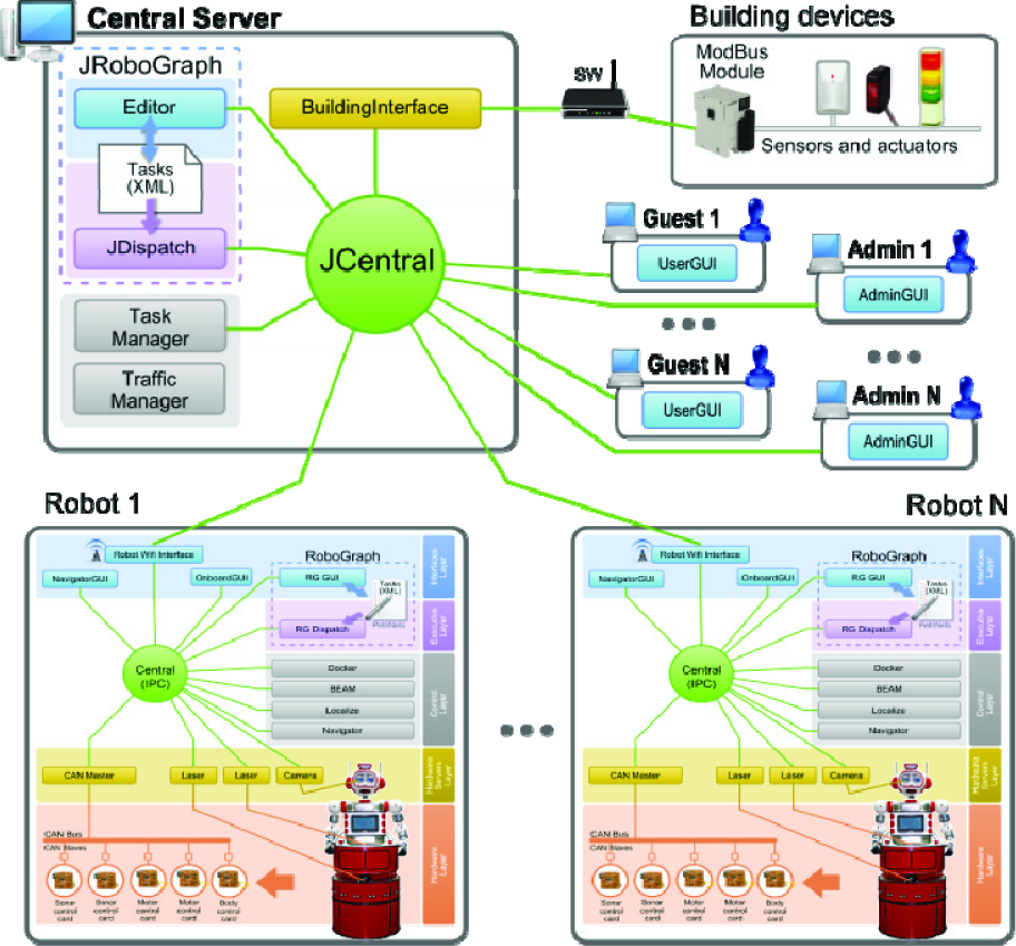
Global system architecture
The robot control architecture includes a module to connect to the central unit using any available wireless connection in the building. So far we have used a couple of alternatives: Wi-Fi, because it is present in most modern buildings and a 3G modem should there be no Wi-Fi.
Much like the robot architecture, the multi-robot executive layer is implemented using RoboGraph. The main difference between the RoboGraph used to control a robot (RG) and the RoboGraph that controls the global application (RGM) is the interface package; RG is connected to IPC while RGM is connected to JIPC. Asides from RGM, the main modules connected via JIPC are:
5.1 Programming and executing tasks
The accomplishment of a task such as “bring a snack to a customer” requires the execution and coordination of different actions by several modules in the architecture. These actions should be executed in a particular sequence controlled by RoboGraph. The execution of each action is usually requested by sending a message to the module in charge of its execution. When the execution of the action is finished, the module sends another message that reports the end of the action.
The “bring a snack to a customer” example will show the interaction between the different modules. To begin, the user will select the snack in the User GUI module that should be running in a terminal in his or her room. Once the user has completed the order and clicks the “order” button, the User GUI module will send a “deliver task” message with information regarding the room and the items to deliver. The task manager module is subscribed to receive those kinds of messages and it will receive a copy. The task manager assigns resources to tasks. In this case it assigns the task to a robot or sets the task in the waiting task queue if there are no robots available. Once a robot is available, it will be assigned to the task and the task manager will send an “ExecutePN” message with the PN name (DeliverItemsRoom), robot name, bar location, room location and items requested as parameters. The “ExecutePN” message is received by the RGM dispatch. This module will load and execute the PN using the parameters received. A very simplified version of the DeliverItemsRoom PN is shown in Figure 7.

Simplified version of DeliverItemsRoom Petri net.
In this PN, places correspond to the publication of messages to modules connected to JIPC, or IPC via Robot-Wi-Fi server and transitions correspond to message receptions. The messages associated to places are:
Regarding the transitions, they will be disbanded when an event occurs. In this example all possible events correspond to the reception of a message:
The implemented version of the PN illustrated in Figure 7 includes transitions for all possible outcomes of the actions. For example, when we request a path from the traffic manager we include another output transition with the message “no path” that is not represented in Figure 7 for the sake of simplicity. Furthermore, some actions are also timed using the RG timers [14].
In this example we use hierarchical PNs where the execution of a PN might request the execution of another PN. Both PNs can be executed by the same dispatch (RG or RGM) or at different levels, as in the example.
5.2 BAS interface
Building devices are usually connected to a network that consists of a bus such as BACnet, optical fibre, Ethernet, ARCNET, RS-232, RS-485 or a wireless network [24]. In this study, we used a few Modbus modules (Schneider OTB 1E0DM9LP) with some LEDs and buttons developed for another application [25]. The buttons represent the building sensors and the LEDs represent the actuators. These Modbus modules were hardwired to the LAN network which includes the central server.
For testing purposes, the building interface module can be replaced by the domotic simulator module that simulates the building devices as a set of inputs and outputs. This module can simulate the devices in two different ways:
Manual. In this case, the GUI shown in Figure 8 allows us to simulate the sensor activation/deactivation manually by pressing the corresponding GUI buttons.
GUI for the “Domotic simulator” module.
Automatic. Different behaviours can be defined in an xml file that is loaded by the simulation module. For example, we can program the file so that a few seconds after activating one output (open door) a sensor (door opened) is activated.
5.3 Interacting with users
There are three types of GUIs that allow users and employees to interact with the assistant system:
Robot onboard GUI. This GUI is shown on the BellBot touchscreen as a way to interact with the robot.
Guest GUI (Figure 9). This is a very simple GUI intended to run on terminals located in the guest's rooms allowing them to request different services such as newspapers, snacks, etc.
User GUI.
Administrator GUI (Figure 10). This GUI includes tools to see the location of all the robots in the building on a map, monitor the state of the robots, see a list of tasks assigned to them and even monitor the on-board sensors.
Administrator GUI.
Besides, users can interact directly with the robot using the touch screen and the robot's social abilities.
The different robots' social abilities operate differently:
BellBot. This robot interacts with users using two touch sensors on the robot's cheeks, two touch sensors on the hands, the touchscreen and the laser sensor.
Sacarino. This robot interacts with users using the touch screen and the Loquendo voice recognition system [26]. Sacarino includes a chatbot for more flexible recognition and provides useful information to the guest (restaurant timetable, shop locations, weather information and other hotel services).
6. Experimental results
The system has been tested in the ETSII building and also in the Hotel Novotel in Valladolid (Spain).
For the tests in the ETSII building we used faculty offices as guests' rooms, one lab as the bar and the lobby as the reception area. The BellBot web page [27] shows some videos with the robot executing some of the tasks and some user interactions. For example, one of the scenarios includes the following steps:
A guest in room 202 orders several items from the hotel bar through a friendly interface.
The supervisory system receives the order, selects a robot to execute the task and commands the RGM dispatch module to execute the DeliverItemsRoom Petri net (Figure 7).
The execution of the Petri net, described in section 5.1, includes the following orders to the robot:
Navigate to the bar (follow the first path, as shown in Figure 7).
Order items (voice and onboard GUI), open the belly box (Figure 3) and wait until the order is completed and confirmed by the barman.
Close the belly box and navigate to room 202 (follow second path, as shown in Figure 7).
Deliver items to guest: open the belly box, request the user to extract the items and wait for confirmation.
Since there are no tasks waiting, the robot is sent to charge.
The ETSII building has no elevators. Therefore, the robot work environment is restricted to one floor. However, in order to test the system in a multi-floor environment, the same map was used for the four floors of a virtual building. A Modbus module (Schneider OTB 1E0DM9LP) [25] together with a PLC was used to simulate the elevator. The trajectories the robot must travel to reach a different floor include one elevator node in the current floor and another elevator node in the destination floor. The robot will request access to the first elevator node from the central server. The central server (building interface module) moves the elevator and opens the door. In our case, the orders are sent to the Modbus OTB and the PLC simulates the elevator. The central server grants access to the robot that moves “inside” the elevator and requests access to the next elevator node. Again, the central server closes the elevator door, moves the elevator and opens the door. Finally, the robot exits the door and keeps following the trajectory in the destination floor which in our case is materially the same.
Other possible scenarios for simulation, include the robot's behaviour while waiting for new tasks. These can be seen on the Bellbot web page.
As for the tests in the hotel (Figure 11), for two months Sacarino has been working, mainly providing information to users and validating the performance of the dialogue system. Its navigation activities are restricted to the floor level since the elevator automation ability was not put in place. Sacarino is able to navigate and escort guests to different locations in the hotel upon request (restaurant, bar and meeting rooms). The objective is to incorporate new functionalities to Sacarino and to validate them during the next year, according to two considerations: system robustness (analyzing maintenance cost) and users' perception of the utility of the service.

Sacarino at the hotel.
7. Conclusions and discussion
The application presented here shows the advantages of using mobile robots for certain routine, daily tasks in hotels. The system uses the two-level centralized communication system (Figure 6) provided by RIDE[14]. The first level communicates all the modules onboard using IPC. The second level connects the different robots, users and the building control unit using JIPC. The division into two communication systems is intended to deal with different levels of communication requirements. Robots can autonomously handle several tasks even if they are eventually disconnected from the central server. However, there are some critical moments when they need to be connected, for example, when they need to request access to the elevators that are controlled from the central server.
The same RIDE programming tool based on Petri nets (RoboGraph) was used to implement the executive layer of each mobile robot and the executive layer of the global application.
Power autonomy is achieved with the use of a recharging mechanism that includes a charging station, an onboard device and a low-level module (docker) that locates the station and docks the robot. This module is also in charge of monitoring the battery level and notifying the task manager when it reaches a critical level. When robots do not have a task assigned to them, they should be charging.
Most of the work in this research was focused on two topics: the first was to build the supervisory central system that integrates all the robots and the BAS and the second was to build robots with social interaction capabilities which could be integrated into this application.
The second topic has been addressed before by several researchers, working on social interaction robots [3, 4], rehabilitation robotics [5, 6, 7], tour guide robots [8] delivery robots [9] and nurse robots [10]. However, most of these applications use only one robot and none of them provide mechanisms to integrate the robots with the building's automation system (BAS). On the other hand, there are applications such as robot based integrated logistics systems [28] which include a supervisory system. The purpose of this supervisory system is to assign missions to robots and to control devices in buildings such as doors and elevators. However, these robots do not have social interaction capabilities.
In this research we integrate both topics using a centralized control system which is in charge of creating new missions according to users' requests and scheduled tasks, assigning missions to robots, monitoring the execution of the missions and coordinating robot actions with the BAS.
Footnotes
8. Acknowledgments
This work has been partially supported by the Spanish Comisión Interministerial de Ciencia y Tecnología, (CICYT) under Project DPI2008-06738-C02 and Project DPI2011-25489, and the Junta de Castilla y León under Project VA013A12-2. The authors would also like to thank anonymous reviewers for their valuable comments and suggestions in improving the quality of the paper.