
Abstract
There is a growing interest in the use of tour guide mobile robots in different environments such as museums, exhibitions and fairs. This type of robot should have autonomy, robust perception and navigation systems, and should also be oriented towards close interaction with humans.
In this paper we present an automatic tour guide system based on a set of mobile platforms that interact with visitors to help them in different tasks. These tasks include giving tours to visitors, helping them find points of interest in a building and providing information about elements in the stands in a fair.
Over the last few years, many tour guide robots have been developed and used in museums and at events. Most of these systems are based on a single robot and they do not include mechanisms to exchange information with the building automation system. The approach presented here uses several robots connected to a central server. The system also includes different devices in the building that are connected through a fieldbus to the central server.
The system was developed with the Robotics Integrated Development Environment (RIDE) and was tested intensively at different events.
1. Introduction
Until recently, service robots were restricted to a very few applications. But that has changed with recent success cases that have already appeared in the market. These cases, such as the Roomba [1] cleaning robot or the PackBot [2] military robot, are specifically designed to help people in particular tasks. The construction of humanoid assistant robots capable of helping people in different ways and maintaining sophisticated communication systems is still far from reality. However, as technology evolves, a greater variety of specific-application robots is emerging. These applications include social interaction robots [3, 4], rehabilitation robots [5, 6, 7], tour guide robots [8], delivery robots [9] and nurse robots [10].
Most tour guide robots, such as Minerva [11], Rhino [12] and Jinny [13], have been used in museums. However, there is a wide area of applications that include fairs and exhibitions; for example, RoboX was designed to interact with visitors at Expo02 [14], and others such as Pearl and Flo [15] to assist elderly people with limited cognitive and physical abilities to enjoy such events.
Several projects have already employed multiple-robot service systems [17, 18], but the solution proposed here includes a mechanism to interact with the Building Automation System (BAS). In addition, it provides a flexible mechanism to define robots' behaviour and the sequence of actions-events on the robot tasks.
The research presented here is oriented to the construction of a tour guide system where robots should be able to execute tasks autonomously. These tasks would include giving tours to visitors, helping them find points of interest and providing information about these points. The system is also integrated in the BAS, which includes different elements such as automatic doors, elevators, sensors and user control panels. A centralized system where all the robots and the BAS are connected to a central server is proposed. All the devices in the BAS are connected to the local network using the Modbus fieldbus over Ethernet. A module in the central server controls all the actuators connected to Modbus and notifies the rest of the system of changes in the sensors.
Tasks can be requested at any time and the system should assign them to robots in an efficient way. In the proposed framework a process in the central server is in charge of allocating the resources needed for each task.
The rest of this paper is organized as follows: the next section introduces the global system architecture. Section 3 presents the robots used in this research, while the robot control architectures are described in section 4. GuideBot includes tools for fast project configuration and programming. These tools are presented in sections 5 and 6. Finally, section 7 presents the results and concludes the paper.
2. GuideBot global architecture
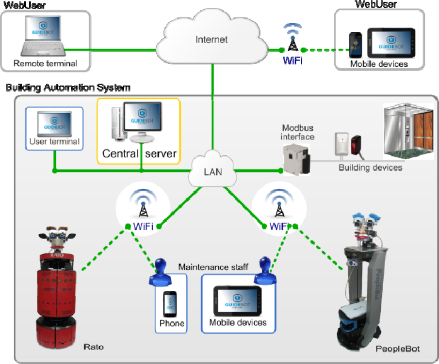
A possible scenario is depicted in Figure 1. Robots are integrated in the building and connected to the central server via Wi-Fi (Figure 2). Users can request robot services interacting directly with the robot or using a visitor GUI from a computer, smartphone or any portable device able to run Java. For remote requests, the central server will decide which robot to send. Employees and maintenance staff can monitor the system from any terminal connected to the local network or Internet.

GuideBot application scenario.
Connections between the different elements of the architecture.
All the running GUIs and the BAS are also connected to the central server. Some of the elements controlled by the BAS that need to interact with the GuideBot system are:
Automatic doors. Robots request the opening of an automatic door from the central server. This server interacts with the BAS to open the door.
Building transportation systems such as elevators and escalators. Robots can request an elevator to move between different floors. A module in the central server is in charge of managing the BAS.
Building interacting sensors. Different building sensors can automatically activate a robot task. For example, a button at some point can be labelled with “press to get a robot” so that visitors can request the services of a robot.
Mobile robots can be connected and disconnected at any time. A central server computer keeps all the relevant information about the global state of the system. All the components or modules need to request and send data through the central server. For example, robots need to:
Send information about their state (position, task being executed, sensor readings, etc.).
Request other elements (modules) to execute some commands such as “open a door”.
Receive information about events such as “door opened” or “elevator in position”.
Receive task execution requests.
The connections between different elements in the GuideBot system are shown in Figure 2. All the building devices in the BAS are connected to Modbus interfaces. These interfaces are connected to the LAN using Ethernet. A program in the central computer (central server) manages all the Modbus communications. The mobile robots are also connected to the central server via Wi-Fi, GPRS or 3G.
The main point when selecting these technologies was robustness. For example, we selected commercial applications that have been proven to be robust in other applications, such as the CAN bus in the car industry. In a similar way, the Modbus protocol was selected to communicate the devices in the building with the central control unit.
Guests and maintenance staff can monitor the system using two different graphic user interfaces (GUIs). Robots that are not doing a task should be connected to the charging stations located near the reception desk (Figure 1) so that users can interact with them and request the available services, for instance different kinds of tours. A typical task might start when one visitor requests a predefined tour.
2.1 Global Framework
The scenario shown in Figure 1 includes robots, guests, employees and the building devices included in the BAS.
The control architecture was developed using RIDE (Robotics Integrated Development Environment) [16]. The resulting modular architecture has the same layers and shares most of the modules with other mobile robot applications developed with RIDE, such as WatchBot [19].
The global architecture shown in Figure 3 is a modular centralized framework where modules are independent processes, most of them running in different CPUs. These modules exchange information using a message publish/subscribe mechanism named JIPC. JIPC provides a central communication process named JCentral (Figure 3) and an interface (Java class) to be used by the different modules that want to communicate through JCentral.

Global system architecture.
The navigation control architecture in each robot – this will be explained in detail in the next section – includes a module to connect to the central unit using a wireless connection available in the building. So far we have been using a couple of alternatives: Wi-Fi because it is present in most modern buildings and a 3G modem for other cases.
The robotics development environment (RIDE [16]) includes a tool named RoboGraph that implements the executive layer (Figure 3), which consists of two modules:
RoboGraph GUI is the programming IDE for defining and debugging application tasks (Petri nets). Tasks are defined as Petri nets and stored in an xml file.
Robograph dispatch loads from an xml file and executes tasks defined as Petri nets. When executing a task this module schedules the different actions of the functional (basic actions), executive (other Petri nets) and interface layers (user and web interfaces) and receives information about the events produced. The interaction with other modules in the architecture is done by publishing and subscribing messages.
Besides RoboGraph, the main modules connected via JIPC are:
3. The robots
Two different robots have been used in this research. The first prototype, named RATO, is based on a B21 base updated in our lab. The second robot, named ShowBot, is a PeopleBot base improved with a mechatronic head, a few sensors and a central computer running all the control and navigation programs. The next sections describe both robots in more detail.
3.1 RATO
Figure 4 shows the front view of robot RATO. RATO is an upgraded B21 with a mechatronic head. It has a powered sound system and a new on-board computer. Since the B21 platforms were discontinued, maintenance and upgrading on a robot has become more and more difficult. Replacing broken sensors, integrating new devices and upgrading the operating system are painful tasks due to the use of the ACCESS.bus, a hardware subsystem within the robot itself that manages communication with some of the on-board sensors. In RATO we replaced the old ACCESS.bus by a CAN bus. RATO has the original ring of Polaroid sonar sensors but the control cards have been replaced by three CAN control cards. Each one of these cards uses a PIC18F458 microcontroller to govern eight sonar sensors and four bumpers. The microcontroller includes a CAN interface and each card is connected to the bus. The on-board computer is also connected to the same bus using a simple USB-to-CAN interface.

The robot RATO.
In a similar way, another CAN card with a PIC18F458 microcontroller manages the eight servos of the robot's head [20].
Later, the motor controllers started giving problems and were replaced by two CAN control cards. This time the dsPIC30F4011 microcontrollers were used to produce the PWM signals to control the translational and rotational velocity.
Finally, in order to integrate buttons on the top of the robot, a generic input/output CAN card was created and added to the robot. The final topology for RATO CAN bus can be seen at the bottom of Figure 7.
CAN fieldbus [21] was considered here because it is widely employed in vehicles and other applications that include an important number of interconnected devices [22], and has already been used in mobile robots.
CAN standard protocol only specifies how to exchange data (level 1 and 2 in the OSI layered model) [23]. As the CAN standard does not define the application layer protocols, such as flow control, device addressing and transportation of data blocks larger than one message, we have designed and implemented a lightweight application layer named RoboCAN [24]. RoboCAN is a simple master-slave protocol where the master is a process running on the on-board computer and the slaves are the control cards. The CAN server handles the connection and disconnection of the different slaves, which can be connected at any time and in any order.
Besides the devices connected to RoboCAN, the robot includes a laser, a camera, a couple of speakers and a microphone.
3.2 ShowBot
This robot is based on a PeopleBot from Mobile Robots. A mechanical framework for the laser, a charging device, a platform for the laptop and a mechatronic head were added to the commercial platform. Figure 5 shows the different elements of the robot.

The robot ShowBot.
The platform is a PeopleBot that provides the motion system and sonar sensors used for navigation. The battery power (three batteries) is included in the base. A framework to integrate the laser-range sensor and the charging device has been added. On top of this framework, a laptop running Linux controls the robot and exchanges information with the central server via Wi-Fi. All the different devices are connected to the control unit (a laptop running Linux OS in this case) using different connections. A CAN card with a PIC18F458 microcontroller manages the ten servos of the robot's head [20]. As in the robot RATO, the CAN bus is connected to the on-board computer using a CAN-USB adapter.
The PeopleBot base is much lighter than the B21, even though it is similar in height. One of the design restrictions for the ShowBot was that the Head must be very light to prevent the robot from tipping over.
The charging device used is common to all our robots. It has also been installed in some Pioneer P3DX and custom-designed robots such as WatchBot [19]. The charging station shown in Figure 6 is the same for all of our robots because the on-board charging device is also the same, and it is installed at the same height in the robots.

Battery charging system.
4. Robot control architecture
The robot control framework (Figures 7 and 8) is a modular centralized architecture where modules are independent processes that communicate with each other using the Inter Process Communication (IPC) [25]. Developed at Carnegie Mellon's Robotics Institute, IPC provides a publication-subscription model for processes to pass messages to each other via a central server program. Each module registers with the central server, and specifies the types of messages it publishes and the types it listens for.

RATO control architecture.

ShowBot control architecture.
Each module corresponds to an independent Linux process running on the on-board computer. The different modules are organized in four sets:
Hardware server layer that includes a set of programs that control different hardware devices.
Control layer that implements the basic control and navigation functionality. Includes reactive control (BEAM), localization (localize), path planning (navigator) and a program that handles the docking manoeuvre (docker).
The executive layer contains a couple of modules to coordinate the sequence of actions that need to be executed by other modules to carry out the current tasks.
The interface layer includes a set of processes to interact with the users and connect to other processes for multi-robot applications.
Certain navigation modules are imported from CARMEN [26], such as localize, navigator and the Pioneer base hardware servers. Unlike CARMEN, however, motion control is divided into high-level planning [27] and lower-level reactive control using the BCM method [28].
4.1 Interface modules
There are several GUI modules that can be used by the programmer to debug and trace the control and hardware server modules. Additionally, one on-board interface module allows users to interact directly with the robot. For example, using this GUI the robots can show the list of possible tours and points of interest. Finally, a robot-Wi-Fi module is used to connect the robot with the central server.
4.2 Executive modules
The same tool (RoboGraph) used to coordinate the JIPC modules to execute a task is also used to coordinate the IPC on-board modules to execute a robot task. The main difference between the RoboGraph used to control a robot (RG) and the RoboGraph that controls the global application (RGM) is the interface package; RG is connected to IPC while RGM is connected to JIPC. A detailed description of this module will be presented in section 5.
4.3 Control modules
The control modules integrate sensor and motion information to provide improved sensor odometry, basic navigation capabilities (localization, path planning and follow path) and basic application specific functions (say text, play sound, move hands, etc.).
This layer implements the main functions in robot navigation (obstacle avoidance, localization, mapping and path planning). The maps are constructed using a scan-matching algorithm [29]. A path planner finds the path in these maps to reach the different navigable points in the environment using the Konolige's local gradient descent planner [30]. The environment in this application is dynamic and the robot might encounter some obstacles that were not present when the map was created. For example, it might encounter obstacles that can change positions (chairs, tables, etc.) or moving obstacles such as people. Robots are able to avoid such obstacles using the BCM reactive control method [28].
For the localization problem, we use a particle filter [31] that uses information from the map, the laser range and the encoders. We have also worked on an IR tag alternative for open and populated environments [32]. This alternative was motivated by the difficulty to match the laser readings with the map in populated environments. This occurs because most of the sensor readings are distances to people instead of static objects in the map.
Even though the control modules for both robots are the same, they use different parameters such as robot dimensions, sensor localization on the robots, accelerations, etc. As in CARMEN, there is a module named param_server (not shown in the figures for the sake of simplicity) that reads these parameters from a configuration file and provides them to the rest of the modules. In this configuration file the parameters for different robots are grouped in sections. The robot name is specified to param_server at start-time so that it loads the parameters for the right robot.
The mobile robots we are using have on-board power for a finite amount of time (from three to five hours). After that time, the robot would require human intervention for extended usage. To achieve true long-term autonomy, we have developed a recharging mechanism, which enables a robot to interrupt its regular operation, go near the charging station and start a docking sequence.
4.4 RATO hardware server modules
The hardware server modules govern hardware interaction, providing an abstract set of actuator and sensor interfaces and isolating the control methods from the hardware details.
It is in the hardware servers layer where the architecture modules for both robots differ the most. This can be observed in Figures 7 and 8. Since RATO electronics were rebuilt, most of the devices are controlled with CAN control cards. These CAN cards are the slaves in the RoboCAN master-slave protocol. The CAN master module obtains information and sends commands to the six slaves and exchanges all this information with the rest of the IPC modules. Slaves can also implement some control. For example, the low-level control loops for rotation and translation velocities are implemented in the CAN slaves that control the motors.
The CAN master module can be seen as a gateway between RoboCAN and IPC in a similar way that Robot Wi-Fi Interface module acts as a gateway between IPC and JIPC.
There are some devices, such as cameras and the laser and the speech system, that have their own control modules because they are not connected to the CAN bus. Some of these devices, such as the laser and sonar, are used in navigation for obstacle avoidance by the BCM method [28]. The speech module is subscribed to two kinds of messages to command the reproduction of a sound file or to reproduce a text included in the message. For the reproduction of a sound file it uses the Linux play command and for text-to-speech reproduction it uses Festival [33].
4.5 ShowBot hardware server modules
Figures 7 and 8 show that the hardware servers layer provides an effective decoupling between hardware and software control modules. The CAN master module in ShowBot (Figure 8) manages only a CAN slave card that controls the robot head. For this robot, the base module handles the base movements and the sonar readings.
The other three modules of this layer (laser, camera and speech) are similar to the RATO modules and they can control the same kinds of devices (lasers, cameras and the sound system, respectively).
5. Programming and configuring a GuideBot project
In this kind of application, having some tool for fast programming and configuring is crucial. Most of the projects we have implemented so far were related to some kind of fair or exposition where the system had to work for a few days. In our experience, the stand distribution and even the tasks that the robot needs to execute are not completely defined until the day before. For these applications, tasks and other parameters, including the map which the robots use to navigate, routes to follow, multimedia files to reproduce, behaviours and text to synthesize need to be easy to change.
For example, at the Xuventude Galicia Net 2008 fair, a new stand was added in the middle of a tour route. In addition, the positions of other stands were changed one day prior to the robot tours. Due to some late alterations in the programme, the behaviour of the robot also needed to be changed from the one planned one week before. Using the tools that will be described in this section we were able to change and test it the day before in less than three hours.
Maps are made off-line using a simple scan-matching algorithm after logging laser data while the robot navigates through the working area. Minor changes can be done manually with a map editor and the complete map can be rebuilt walking the robot again and collecting new data. Finally, maps can also be constructed from a CAD map. This option is rarely used for final maps because they are quite different from the maps created from sensor log files due to the furniture and other static obstacles not included in the CAD. However, we use it as a first approach for simulation purposes before the real environment is constructed.
In GuideBot, tasks can be easily modified thanks to the RoboGraph tool, as will be shown in the next subsection. However, the sequences of events in a task are rarely changed. For example, the tour tasks main sequence, which consists of extracting a new point to visit, going to the point and playing a multimedia file, is usually the same for different projects. However, some parameters, such as the points to visit or the multimedia files to reproduce, need to be changed.
5.1 Programming and executing tasks
The accomplishment of a task such as “games stands tour” requires the execution and coordination of different actions by several modules on the architecture. These actions should be executed in a particular sequence controlled by RoboGraph. The execution of each action is usually requested by sending a message to the module in charge of its execution. When the execution of that action is finished, the module sends another message that reports the end of the action. These sequences of actions are defined using Petri nets at different levels of abstraction:
Primitive tasks. These Petri nets define basic sequences of actions such as “blink one eye” or “navigate to point a”. Some of these sequences use parameters such as the eye for the “blink one eye” primitive or the point a in the “navigate to point a” primitive.
Main tasks. This set includes all the tasks that can be directly requested by a user, such as the “multimedia stands tour” example mentioned before. The actions included can be primitive actions or basic actions requested from any module in the system.
5.1.1 Primitive tasks
The “wink one eye” simple example will show the interaction between the different modules in a basic primitive task. The Petri net that defines this primitive task is presented in Figure 9; it is executed by the dispatch module included in RoboGraph (Figures 7 and 8).

wink_one_eye Petri net.
There is only one module involved in the execution of this primitive – the CAN master module. To begin, dispatch will receive a run_petri_net message with the name of the net (wink_one_eye) as a parameter. Dispatch will load the net from the corresponding file and it will start executing the actions associated to the initial places.
There is only one initial place (“open eyes”) and one final place (P15). The execution of a net will finish when there are no marks in any place or all the marks are located in final places. Only the places represented with empty circles in Figure 9 have some action associated. The corresponding actions for those places are:
Transitions represented as dark rectangles in Figure 9 have some conditions associated to them. All the other transitions do not have conditions associated and will be fired as soon as all the input places are marked. For example, transition T6 has no condition associated and is going to be fired as soon as places P7 and P8 are marked. The conditions associated to transitions are:
Following this pattern, several primitives have been defined that can be classified in different groups:
Facial expressions. This set includes actions whose goal is to position the head servos to represent different facial expressions such as sad, happy, bored, angry, frightened, astonished, etc. All of them command the CAN server module to move some servos to particular positions and wait until all the servos reach the commanded positions.
Head gestures. This set includes basic gestures such as “blink eye”, “wink eye”, “shake head”, “nod head”, “head talk”
Navigation basic tasks. All the basic tasks that include robot motion can be included in this group. For example, “navigate to point a”, “face people”.
Most of the tasks described so far are basic primitive tasks without subtasks, but there are also some primitives such as “explain point” that can include the execution of other tasks. Figure 10 shows a simplified Petri net for the “explain point” task that includes the execution of “face people”, “head talk” and “rest expression” primitives. Initially, the “address people” task is executed and two subtasks are then executed in parallel: “head talk”, which basically opens and closes the mouth pretending that the robot is speaking, and “synthesize text”, which reproduces a text using the speech module. When the text is reproduced, the “head talk” task is killed. After both tasks finish, a “rest expression” task is executed to set the face in the rest position because since the “head talk” task was killed the robot head could end in a funny position. Finally, after the rest expression is reached, the “explain point” task ends.

explain_point Petri net.
The execution of a task corresponds to the publication of the run_petri_net message that includes the name of the Petri net and its parameters. In Figure 10, actions associated to places like “face people”, “head talk” and “rest expression” correspond to the publication of this message. This message is received by dispatch itself, which starts the execution of the corresponding Petri net. When dispatch completes the execution of a task (Petri net), a petri_net_ended message with the Petri net name and identifier is issued. In Figure 10 conditions associated to transitions “people faced”, “head talk finished” and “expression reached” include the petri_net_ended message. Finally, it is important to notice that some tasks (Petri nets) such as “head talk” might be an endless loop, since it is difficult to know in advance the time it will take to synthesize a text. Instead, the task is started when the robot starts speaking and killed once the text is reproduced. For that purpose, the “kill head talk” place has a kill_petri_net message associated that will end the “head_talk” Petri net.
5.1.2 Main tasks
Tasks that can be directly requested by users are named main tasks and only one task of this type can be running in the robot at any point in time. However, from the RoboGraph point of view, all the tasks are managed in the same way. Main tasks typically include the execution of several primitives. Different kinds of events can launch the execution of one of these tasks. Some of them can be requested directly by a user from a robot, while others can be requested from a user panel at some point in the environment, which can be attended by any robot. In multi-robot applications, all the main tasks are assigned by the Task Manager (Figure 3) to robots who report execution status. This way, users and managers can use a GUI to see the state of each robot and the task that is taking place.
Figure 11 shows a simplified version of the “give_tour” task that uses the “navigate_to_point” and “show_point” primitives. The complete version of this net considers different outcomes of the primitive executions and times for their execution.

give_tour Petri net.
A special main task is the “Battery_charge” that is started when the robot reports a battery low or battery panic status. The difference is that with battery low the robot finishes the execution of the current main task, while with battery panic the current main task is cancelled.
5.1.3 Configuring tasks
Using the RoboGraph Editor module, tasks can be easily changed with a simple GUI, which makes GuideBot very versatile. However, usually only some task parameters such as tours, points on these tours, points of interest (charging station, wait point, etc.) change from one project to the next. In order to speed up the configuration of new projects a configuration GUI that allows the definition of some parameters such as points of interest and tours has been implemented.
Figure 12 shows the main window of this interface.

GuideBot configuration GUI.
5.2 Configuring the Building Automation System
Building devices are usually connected to a network that consists of a bus (such as BACnet), optical fibre, Ethernet, ARCNET, RS-232, RS-485 or a wireless network [34]. In this research all the building devices are connected to some I/O Modbus interface. These I/O Modbus interfaces are connected via Ethernet using the Modbus protocol to the central server. Within the central server a module named BuildingInterface (Figure 3) manages all the information between the I/O Modbus interfaces and the rest of the system.
The BuildingInterface module is generic and does not need to be changed for new projects. This is achieved by keeping the project-specific settings in an xml file that stores the parameters of the I/O network interfaces and their settings, including IP addresses, ports and inputs, to be sampled together with the sampling periods. A GUI (Figure 13) simplifies the task to configure the project parameters on this file. The same GUI can also be used to monitor the Modbus devices showing their status. Finally, for developing purposes, the BuildingInterface module can be replaced by a simulator.

BuildingInterface GUI module in editor mode.
One of the I/O Modbus interfaces used here (Schneider OTB 1E0DM9LP) is shown in Figure 14. These modules have already been used in the RoboWatch application [35]. The buttons represent the building sensors and the LEDs represent the actuators. These Modbus modules are hardwired to the LAN network that includes the central server.

I/O Modbus interface with a set of inputs (buttons) and outputs (LEDs) connected.
6. Interacting with users
There are three types of GUIs that allow users and employees to interact with the GuideBot system:
Robot onboard GUI. This GUI is shown on the BellBot touch screen and is used to interact with the robot. It includes some frames to display videos and information about the points of interest.
Panel visitors GUI. This is a simple GUI intended to run on terminals located at the different places in the building where users can request robot services.
Administrator GUI (Figure 15). This GUI includes tools to see the location of all the robots in the building maps, monitor the state of the robots and even monitor on-board sensors like the cameras.

Administrator GUI.
An important issue in this kind of application is the robot's social abilities. According to various researchers, body language is thought to account for 50 to 70 per cent of all communication [36]. There is a lot of research being done in this field on different facial expressions. For example, Birdwhistell [36] estimated that a human being can make and recognize around 250,000 facial expressions.
As we mentioned before, both robots presented here include a library of primitives for facial expressions and head gestures that constitute the base of the robot body language.
While the robot is waiting for a task to be assigned, a waiting task includes several random and reactive movements. The corresponding waiting Petri net includes the execution of several random gestures like blinking and yawning. It also includes reactions to some human actions. Touch is detected by touch (tactile) sensors, and lasers detect anyone or anything approaching. The waiting task is killed every time a new main task is assigned and is started again when the main task is finished.
Different robot behaviours are also part of tasks. These include waiting for the user to do something, or talking. Since some users do not have “good manners” with robots and leave the robot waiting for an answer, most of these user events have a timeout and a default answer.
7. Results and conclusions
The GuideBot application presented here is a guide robot system that includes mechanisms to integrate building devices in a simple and modular way using Modbus over Ethernet. Special attention has been paid to orienting GuideBot to a multi-robot system that is easy to install and configure for new projects.
The system uses the two-level centralized communication system (Figure 3) provided by RIDE [16]. The first level communicates all the modules on-board using IPC. The second level connects the different robots, users and the building control unit using JIPC. The division into two communication systems is intended to deal with different levels of communication requirements. Robots can handle several tasks autonomously even if they get eventually disconnected from the central server.
Task and robot behaviours are defined at different levels using Petri nets with the RoboGraph tool.
Power autonomy is achieved with a recharging mechanism that includes a charging station, an on-board device and a low-level module (docker) that locates the station and docks the robot. This module is also in charge of monitoring the battery level and notifying the Task manager if it reaches a critical level. Robots that have no task assigned are sent to the charging stations.
7.1 Applications installed and experiments
The system has been tested in the ETSII building and applied in several editions of the Xuventude Galiza Net fair (2007, 2008 and 2009), as well as during the “forum Orienta” celebrated in the IFEVI (2008).
For the tests in the ETSII building we define points of interest in faculty offices and laboratories simulating a museum environment. The charging point is located in one of the corridors. Several I/O Modbus interfaces (Schneider OTB 1E0DM9LP) with buttons (inputs) and LEDs (outputs) have been used as part of the building Modbus network.
For the Xuventude Galiza Net projects (Figure 16) the points of interest were defined in front of different stands and the waiting point was set at the entrance of the main lobby. While waiting, robots use the laser to detect a person entering the area in front of them and invite them to interact with it.

RATO at the XGN fair.
The main problems found in these projects were related to navigation and interaction functions. Regarding navigation functions, localization was the main source of problems because the robot was often encircled by a lot of people and the sensors did not “see” the map references. When this situation continues for a long time, the robot might get lost. The solution to this problem for some environments was the low-cost localization system presented in [37]. Regarding interaction functions, the robot behaviour and expressions were changed based on the feedback obtained by users during the applications described above. The main changes are explained as “actions taken” in the next subsection (lessons learned).
In addition to these projects, we also carried out a set of experiments in order to evaluate the performance of the solution proposed here. These experiments are focused on measuring the reaction times derived from events produced by users. Two different cases can be considered:
Local reaction times. The events are produced and managed locally on the robot.
Global reaction times. The events are managed by the central system. They can be produced in the robot or in sensors in the building connected to the Modbus interface. The event is transmitted to the central system, which decides the action to be taken. The decision is then transmitted to the robot.
Next we will evaluate the reaction time for one event produced in a sensor connected to a Modbus interface. We consider this case because it includes almost all the components described here. The central server computer is an Intel® Core™ i3 CPU 540 @ 3.07GHz and the robot onboard laptop is an Intel® Core™2 CPU T5600 @ 1.83GHz.
The steps taken from the moment that the sensor is activated until the robot starts moving are listed in Table 1. Steps T2 to T9 are managed by the modules running in the central server (Figure 3) and include JIPC messages. Steps T9 to T14 are managed by modules on the on-board control unit and include IPC messages.
Sequence of actions during the robot reaction to a domotic event.

Table 2 shows the times in milliseconds for the actions listed in Table 1. The first row (Modbus) is obtained analytically, taking into account that the protocol used in Modbus is a master/slave. The master (BuidingInterface module in Figure 3) queries each slave device (Modbus interface) every 200 msec. The delay in the Modbus interface was not considered here. The rest of the data shown in Table 2 were obtained experimentally.
Robot reaction times in the case of events produced in some of the sensors connected to Modbus devices. Times are milliseconds.

The series of data in Table 2 are also shown in green in Figure 17. The red line represents the times obtained when a mini-ITX VIA EPIA EN1200 CPU is used onboard the robot. As can be seen, the times on the central server modules (Traffic Manager, Task Manager and RoboGraph) are very similar in both cases. However, the times on the robot modules are very different because of the limited computing capacity in the EPIA CPU.
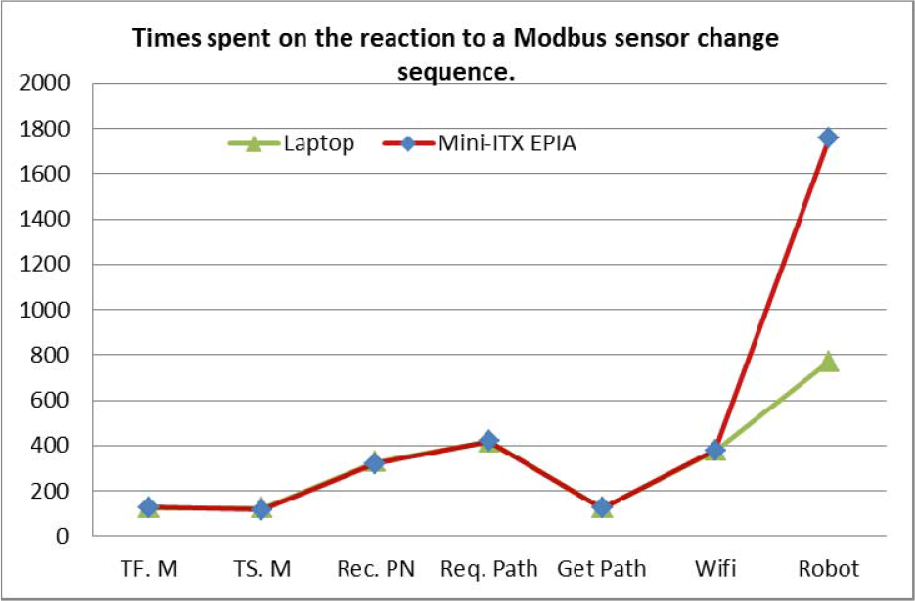
Times spent by the different modules in the sequence of actions taken by the system when a sensor connected to a Modbus module is activated.
The second row in Table 2 (Tf.M in Figure 17) represents the time between actions T2 and T3 in Table 1. The third row (Ts.M) corresponds to the time between actions T3 and T4. In both cases 95% of the time is spent in the JIPC communications.
RoboGraph (RG) times are shown in three different rows: the first shows the time between T4 and T5, the second between T5 and T6 and the third between T6 and T8. The first value (Rec. PN) is quite big (329 msec) because the system requires the sensor to remain active for 200 milliseconds before commanding the execution of the corresponding PN. The purpose of this delay is to avoid spurious readings. Starting the PN with the RoboGraph module also implies time consumption because it is necessary to load the data from the PN xml file.
The row labelled as Robot Wi-Fi Int. measures the elapsed time from when the central control issues the message to when the robot receives it. This time depends on the characteristics of the Wi-Fi. We are using the Wi-Fi provided by the University of Vigo.
Finally, the last row (Robot) represents the elapsed time between the robot receiving the message and the robot starting to move (from action T8 to T14 in Table 1).
7.2 Lessons learned
From the projects described above, we have learned several lessons.
Action taken: This situation was minimized by changing the tour task so that, after finishing a visit to a point of interest, the robot asks for confirmation in order to continue the tour. If the user does not want to continue or the robot does not get answers for a limited amount of time, the tour will conclude.
Action taken: In order to catch people's attention it is important to detect users and let them know about the different actions that they can take to interact with the robot.
Action taken: A set of configuration tools described in section 5 have been developed to change the tasks and robot behaviour (changing the Petri nets in a graphical editor), the maps where the robots have to navigate, the routes to follow, the multimedia files to reproduce or the text to synthesize.
Action taken: We have reduced the reaction times to the values shown above.
The objective in our current research is to incorporate new functionalities into the GuideBot application based on visitors' feedback. These functionalities will be further tested and refined in new projects.
Footnotes
8. Acknowledgments
This work has been partially supported by the Spanish Comisión Interministerial de Ciencia y Tecnología, (CICYT) under Project DPI2008-06738-C02 and Project DPI2011-25489. The authors would also like to thank the anonymous reviewers for their valuable comments and suggestions to improve the quality of the paper.