
Abstract
This paper presents a comparison study of two important three-degree-of-freedom (DOF) parallel manipulators, the Sprint Z3 head and the A3 head, both commonly used in industry. As an initial step, the inverse kinematics are derived and an analysis of two classes of limbs is carried out via screw theory. For comparison, three transmission indices are then defined to describe their motion/force transmission performance. Based on the same main parameters, the compared results reveal some distinct characteristics in addition to the similarities between the two parallel manipulators. To a certain extent, the A3 head outperforms the common Sprint Z3 head, providing a new and satisfactory option for a machine tool head in industry.
1. Introduction
In theory, parallel manipulators are capable of answering the increasing industrial need for high stiffness, compactness, load-to-weight ratio, accuracy, etc. For this reason, parallel manipulators are preferable to serial ones in some applications. In general, a parallel manipulator consists of a moving platform that is connected to a fixed base by means of several limbs.
There has been extensive attention given to parallel manipulators since Stewart developed the Gough-Stewart platform [1] for use as an aircraft simulator [2]. A wealth of research has been published on six-degree-of-freedom (DOF) Stewart-like parallel manipulators, and researchers have come to realize their limitations due to complex direct kinematics, unsatisfactory workspace, and poor orientation capability [3]. However, it is possible for so-called defective parallel manipulators with fewer than six DOFs to overcome these disadvantages while retaining the advantages of parallel manipulators [4]. A significant amount of research has recently been devoted to low-mobility parallel manipulators. In fact, most of the parallel manipulators used successfully in industrial applications belong to the low-mobility category. Examples of such cases are the Delta [5], Tricept [6], Exechon [7], and Sprint Z3 heads [8], among others. Especially in thin-wall machining applications for structural aluminium aerospace components, the emergence of the Sprint Z3 tool head (Figure 1) produced by the DS Technologie Company in Germany [8] has attracted widespread attention from the machine tool user community. Many advantages of the Sprint Z3 head have been shown, including high speed, high rigidity, good dexterity, and large orientation capability [9, 10]. Inspired by the prototype of the Sprint Z3 head, a new tool head named A3 (Figure 2), generating the same DOFs as the Sprint Z3 head, i.e., 1T2R DOFs (one translation and two rotations), was developed by Huang et al. [11] at Tianjin University, China.

Model of Sprint Z3 head [8]

CAD model of A3 head
Both the Sprint Z3 and the A3 heads are so-called 3-[PP]S parallel mechanisms, defined as mechanisms whose three spherical joints move in vertical planes intersecting at a common line [12]. Such manipulators are referred to as zero-torsion mechanisms. Due to their similarities in topological configuration, they have some properties in common. However, as architectures of industrial prototypes there is some variation. Thus, it is necessary and reasonable to obtain a better understanding of this type of parallel manipulator by studying the similarities and differences to facilitate better use of these tool heads in industry.
To date, many research activities have concentrated on the development of high-rigidity and good-dexterity heavy-duty tool heads comprising 3-DOF parallel manipulators in application. Significant efforts have been directed towards analysing the Sprint Z3 and A3 heads, including inverse and direct kinematic analyses, dynamic analysis, and analysis of workspaces and orientation capabilities [13–16]. However, as far as the authors are aware, there has not yet been published a systematic comparison of the two parallel manipulators. In addition, no existing literature considers their performance in terms of the motion/force transmission capabilities, despite the well-known fact that the key function of a parallel manipulator is to transmit motion/force between its input members and output members.
This paper supplements previous efforts with regard to motion/force transmissibility analysis based on the theory of screws, and subsequently concentrates on the comparison of the two 3-DOF parallel manipulators commonly used in industry [17]. The transmission performance atlases are illustrated based on three proposed transmission indices to depict the similarities and distinctions between the two parallel manipulators. In addition, the good transmission workspaces are correspondingly presented for comparison purposes when the same main parameters are given.
The rest of this paper is arranged as follows. The mechanisms of the Sprint Z3 head and the A3 head are described and their inverse kinematics equations are derived in Section 2. In Section 3, a motion/force transmission analysis using three indices based on screw theory is presented. The compared results of the motion/force transmission performance for the Sprint Z3 head and the A3 head are shown in Section 4. Finally, the development of the A3 tool head and some conclusions are discussed in Section 5 and Section 6, respectively.
2. Structure description and kinematic analysis
2.1 Structure description
Both the Sprint Z3 head and the A3 head have three DOFs, in terms of one translation and two rotations, which then produce other parasitic motions. They can realize the function of serial A/B-axis tool heads and the linked movement of the two rotational DOFs. In general, both these parallel tool heads are designed to implement high-speed five-axis milling applications by combining the head's three DOFs with another two translational DOFs, thereby generating a large translational workspace with the hybrid architecture.
The architecture behind the Sprint Z3 head is a 3-PRS parallel kinematic mechanism (Figure 3). The moving platform is connected to a fixed base with three identical limbs. Each limb consists of a prismatic joint (P), a revolute joint (R) and a spherical joint (S) in series, connecting the fixed base to the moving platform. The P joint is actuated. All the joints connected to the base and mobile platform are symmetrically distributed at vertices of the equilateral triangles.

Schematics of 3-PRS parallel manipulator
The schematic diagram given in Figure 4 is a well-known 3-RPS parallel mechanism, which is exactly the architecture behind the A3 tool head. The moving platform is symmetrically connected to a base with three identical limbs. Each limb consists of a revolute joint (R), an actuated prismatic joint (P), and a spherical joint (S) in series. The differences in schematic appearance between the Z3 head and A3 head are the distributing sequences in all limbs.

Schematics of a 3-RPS parallel mechanism
2.2 Inverse kinematic analysis
The inverse kinematics of both the 3-DOF spatial parallel manipulators under investigation here have already been intensively studied [15, 16]. In this paper, we merely briefly present the results of the inverse kinematics analysis and point out some particular aspects.
As shown in Figure 3 and Figure 4, the Cartesian reference coordinate frame O{X, Y, Z} is located at the centre point O of the fixed triangle base platform. A moving coordinate frame o{x, y, z} is attached to the moving platform at centre point o. Considering that both manipulators have two rotations and one translation, we use the Tilt-and-Torsion (T&T) angles (φ, θ, σ) to describe the orientation of the moving platform, where φ, θ, σ are the azimuth, tilt, and torsion angles, respectively [12]. Here, we let σ be equal to 0, indicating the zero-torsion property of this group of manipulators.
Under this description, the rotation matrix can be derived as follows:

First, we will carry out the inverse kinematic analysis of the Sprint Z3 head. In the reference coordinate frame O{X, Y, Z}:

where αi =(2i–3)π/3, R is the radius of the circumscribed circle of the base triangle, and hi is the height of the i-th R joint (equalling the Z value of the R joint in the reference coordinate frame).

where i = 1, 2, 3, p' i is the position vector of the i-th S joint in the moving coordinate frame, Pi is the position vector of the i-th S joints in the reference coordinate frame, and t is the vector from point O, the origin of base frame, to point o, the origin of the moving frame.
Since the length L of each limb is a constant, we can solve the inverse kinematics via the following formula:

Next, we will consider the inverse kinematic analysis of the A3 head, carried out in the same way. The solution for a 3-RPS manipulator is written as:

where di is the unit vector in the direction of the i-th limb, R is the rotational matrix mentioned above, si is the coordinate vector of the i-th S joint measured in the moving frame, t is the vector from point O, the origin of the base frame, to point O', the origin of the moving frame, and ai is the position vector of the i-th R joint measured in the reference coordinate frame.
Through Eqs. (4) and (5), we can solve the inverse kinematic solutions of the Sprint Z3 and the A3 heads, respectively. It should be mentioned that the same practically realizable forced movements along the X and Y coordinates are reduced when taking φ, θ, z as generalized coordinates. These movements are referred to as the parasitic motions, which are dependent upon the generalized coordinates:

Here, we can derive two parasitic motions instead of three; this is different to [10] and [18] because zero-Torsion T&T angles are used to describe the orientation of the platform. The relationships between the values of x/r, y/r and the two generalized coordinate angles φ, θ are shown in Figure 5 and Figure 6, respectively.
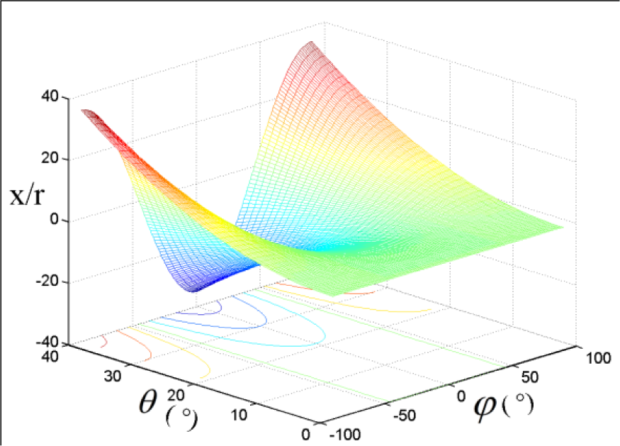
The relationship between x/r and the two generalized coordinate angles φ, θ

The relationship between y/r and the two generalized coordinate angles φ, θ
3. Motion/force transmission performance analysis
3.1 Analysis of two classes of limbs in screw theory
In this contribution, screw theory will be employed as the mathematical resource for the analysis of motion/force transmission of parallel manipulators. The theory of screws has been demonstrated to be an easy and efficient mathematical tool for solving both the first-order and higher-order kinematic analyses of closed chains [19]. Normally, twists and wrenches are screws that indicate the instantaneous motions of a rigid body and a system of forces or moments applied on a rigid body, respectively. One of the merits of screw theory in analysing the twist and wrench in parallel manipulators is that they are invariant with respect to changes of coordinate frame [20].
As mentioned in Section 2.1, the Sprint Z3 head has three identical PRS limbs (Figure 7), while the A3 head has three identical RPS limbs (Figure 8). We consider these two classes of five-DOF limbs via screw theory, wherein the S joint can be regarded as a combination of three R joints. As for the PRS limb, in the local coordinate frame attached to the R joints in Figure 7, five twist screws can be written as:


where α is the angle between the limb and x'-axis. The five twist screws are independent, and thus have only one reciprocal screw, which is referred to as the constraint wrench screw.

Indeed, the constraint wrench screw $c denotes a pure force in the direction of the y'-axis passing through the centre of S joint. Every PRS limb affords five DOFs while supplying a constraint force. Therefore, a Sprint Z3 head bears three pure constraint forces limiting three DOFs, i.e., two translational DOFs and one rotational DOF.

PRS limb in Sprint Z3 head

RPS limb in A3 head
Since the P joint connected to the base is actuated, the corresponding screw is denoted as an input twist screw, which can be expressed as:

If we let the input twist be locked for the time being, a new unit wrench, $T, which is reciprocal to all $i (i = 2, 3, 4, 5) except for $I, and is different from $c, can then be found:

The unit wrench $T is referred to as the transmission wrench. Physically, it is the unit wrench of actuation imposed by the actuated joint on the mobile platform. This transmission wrench $T is a pure force in the direction of the limb. Thus, as an integrated parallel manipulator, a Sprint Z3 head has three input twist screws and three corresponding transmission wrenches.
If we lock any two actuated joints to leave only one actuated joint, the manipulator will be single-DOF for the time being. In this case, only the unlocked transmission wrench represented by $Ti can contribute to the moving platform, while all other transmission wrenches apply no work. In other words, the two locked transmission wrenches $Tj (j = 1, 2, 3; j ≠ i) can be regarded as additional constraint wrenches at this time. Thereby, we can achieve one related output twist $Oi, as follows:

For details on the rigorous proof and calculation process, the reader is referred to [17]. In a similar way, we can lock any other two actuated joints yielding other output twists. Thus, we can accordingly achieve three output twists in this manipulator.
It is straightforward to demonstrate that a similar procedure yields the twist and wrench analysis solution of an RPS limb in the A3 head. With respect to the local coordinate frame attached to the R joints (Figure 8), five twist screws can be written as:


In sum, for integrated parallel manipulators, both in the Sprint Z3 head and the A3 head, we can correspondingly achieve three input twists, three transmission wrenches and three output twists, which will be used in the performance analysis of the parallel manipulator in terms of the motion/force transmissibility in the following section.
3.2 Performance index considering motion/force transmissibility
As is well known, the essential roles of a parallel mechanism are to generate output motion, i.e., transmitting motion/force from its input members to its output members, and to bear the external payloads, i.e., transmitting motion/force from its output members to its input members. Thus, the transmission performance should be considered together with the inputs and outputs. The three indices input, output, and local motion/force transmission capabilities are defined in the following. We should note that the theoretical basis of the corresponding indices has been presented in our previous work [17].
a. Input transmission index
In a parallel manipulator, the actuators are always considered as the input members. To evaluate the motion/force transmissibility of the i-th input member, the power coefficient between input twist and the related transmission wrench in the i-th limb is defined as the input transmission index. This can be expressed as:
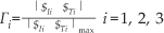
where $ Ii and $ Ti are as mentioned in Section 3.1, and denotes the reciprocal product in screw theory operation. The physical meanings of the denominator elements |$Ii $Ti | max and numerator elements |$Ii $Ti | are the actual power and the potential maximal power of the input members, respectively.
For an integrated parallel manipulator, we consider the minimum value of Gamma;i of every limb as the input transmission index of the whole manipulator.
b. Output transmission index
In a similar way, the output transmission index of the i-th limb can be defined as:

where $Ti and $Oi are the transmission wrench screw and the related output twist screw in the i-th limb. The index can be used to evaluate the motion/force transmission performance among the output members. Also, we take the minimum value of Λi of every limb as the output transmission index of the whole manipulator:

c. Local transmission index
For an integrated parallel manipulator, the transmission performance both in inputs and in outputs is supposed to behave well. Thus, it is necessary and reasonable to take the whole manipulator, including both input and output members, into account when evaluating the motion/force transmission performance. Thus, a local transmission index is defined as:

In this section, three indices have been defined to analyse the motion/force transmission capability in a parallel manipulator. Three points should be noted here: i) all these three indices are frame-invariant, which means the advantages of screw theory can be exploited; ii) since all these three indices indicate the motion/force transmission power coefficients of the manipulator, they all range from 0 to 1; iii) in order to obtain good transmissibility between input and output members, the three indices should be as large as possible. Conventionally, a value of Δ ≥ sin45 ≈0.7 is considered satisfactory, meaning that the parallel manipulator shows good motion/force transmission capability at the local configurations.
4. Comparison between the Sprint Z3 and A3 head based on transmission indices
Based on the proposed three indices, we can analyse and manifest the motion/force transmission performance of the Sprint Z3 and A3 heads, respectively. Without loss of generality, we can assume certain parameters for these manipulators: R = 250mm, r = 200mm, and L = 500mm for the purposes of comparison.
As these tool heads both generate three DOFs including one translation and two rotations, it is difficult to describe the transmission performance considering both the translational and rotational DOFs in one two-dimensional atlas. Thus, the motion/force transmissibility in the translational DOF and rotational DOFs should be taken into account separately.
Firstly, in the translational direction, the relationship between the local transmission index, Δ, and value, Z, is illustrated. Figure 9 and Figure 10 show the relationships between index Δ and value Z by fixing the two rotational angles φ = θ = 0 in the Sprint Z3 and A3 heads, respectively.

Relationship between local transmission index Δ and value Z in the Sprint Z3 head

Relationship between local transmission index Δ and value Z in the A3 head
Figure 9 demonstrates that the local transmission index, Δ, does not vary with the value, Z, for the Sprint Z3 head. This is due to the property that all actuation direction is parallel to the Z-axis, so the motion/force transmission is performed homogeneously along the Z-axis. This characteristic has been analysed theoretically in [21]. In contrast, the local transmission index generally increases with Z for the A3 head (Figure 10). The index approaches a maximum value of 1 as the telescopic limbs extend out to infinity and become parallel, yielding best transmission performance. Dimensional restrictions of the mechanism prohibit this, except in one particular case. When the radii of the platform and base are equal, the three limbs will be parallel with both rotational angles fixed, φ = θ =0. In this case, the motion/force transmissibility of the A3 head does not vary along the Z-axis (homogeneously along the Z-axis); the same is true with the Sprint Z3 tool head.
These analytical results lay down a theoretical foundation for the determination of the parameters of the A3 head. We now modify the assumed parameters to include the equal radius condition for the two manipulators:, R = r = 250mm, L =500mm. These figures relate to the optimal results presented in [22].
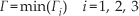
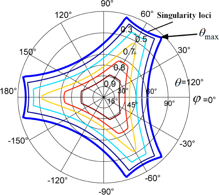
Secondly, for the rotational workspace, we should evaluate the motion/force transmissibility with the help of performance atlases. With the translational position arbitrarily fixed at x = 0, y = 0, z = 500mm, the performance atlases of input transmission index, output transmission index, and local transmission index of the Sprint Z3 head are illustrated in Figures 11, 12, and 13, respectively. Figure 14 shows the distribution of the input transmission index of the A3 head within the orientation workspace, while Figure 15 depicts the distributions of both the output transmission index and the local transmission index of the A3 head. All the performance atlases are illustrated in polar coordinates. In particular, the thick blue lines in Figures 11–13 and Figure 15 show the singularity loci characterized by a local transmission index equal to zero (Δ = 0). At the singular configurations, the manipulators cannot transmit any power between the input and output members.

Distribution of the input transmission index in the orientation workspace of the Sprint Z3 head

Distribution of the output transmission index in the orientation workspace of the Sprint Z3 tool head
Distribution of the local transmission index in the orientation workspace of the Sprint Z3 tool head

Distribution of the input transmission index in the rotational workspace of the A3 head
Distribution of the output and local transmission indices in the rotational workspace of the A3 head
By comparing the input transmission indices, Γ, illustrated in Figures 11 and 14, it can be seen that the input transmission index in the Sprint Z3 head is less than unity while the index in the A3 head is always equal to unity. Considering the physical meaning, when the directions of the input twist $I and the related transmission wrench $T are collinear, such as in the RPS, SPS, and UPS limbs (U denotes the universal joint) where the P joint is actuated, the input transmission index is always equal to its maximum value of 1. In this case, the potential power can be fully transmitted from its input members. Since the input transmission index, Γ, in the A3 head is equal to unity, we can simplify Eq (28) as:

which means the local transmission index Δ is equal to the output transmission index Λ for any configuration of the A3 head.
By comparing Figures 13 and 15, it can be seen that the maximum reachable tilt angle, θmax, is a little larger for the A3 head than for the Sprint Z3 head with the same structural parameters. That is to say the rotational workspace of the A3 head is larger than the Sprint Z3 head with the same structural parameters and fixed translational position.
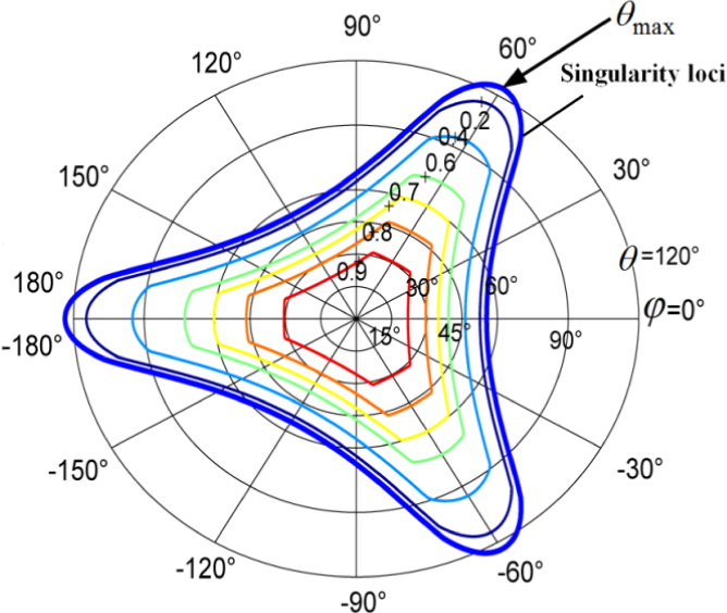
The local transmission performance does not differ too much between the Sprint Z3 head and the A3 head. Figures 16 and 17 illustrate the respective good transmission workspaces (GTW), which are enclosed by index Δ ≥ 0.7. The two figures both use a combined coordinates system including two rotational polar axes and one translational Z-axis. According to the comparison of the two GTW distributions, the GTW of the Sprint Z3 head is a little larger than that of the A3 head.
GTW of Sprint Z3 head enclosed by index Δ ≥ 0.7

GTW of A3 head enclosed by index Δ ≥ 0.7
5. Development of A3 tool head
An A3 tool head mechanism has been manufactured by Tianjin University in China (Figure 18), which will further contribute to experiments on motion/force transmission performance.
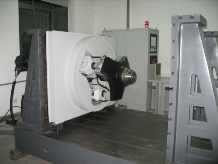
Prototype of A3 tool head
6. Conclusions
The Sprint Z3 head and the A3 head share common properties, such as similar actuation in the prismatic pairs, 1T2R DOFs with zero-torsion capability, and the same parasitic motions. On the other hand, from the comparison study of the two important tool heads in industry in terms of motion/force transmission performance, some distinctions can be drawn:
In the case of unequal base and mobile platform radii, the motion/force transmission capability of the A3 head gets better as the telescopic limbs extend. In the case of equal radii, the A3 head mimics the Sprint Z3 head's homogenous transmission capability along the Z-axis. In contrast, due to its structural properties the Sprint Z3 head can always possess homogeneous motion/force transmission performance, regardless of the parameters. The motion/force transmission power coefficient in the input members of the Sprint Z3 head is always less than that of the A3 head, which has an input transmission index of unity. The power from the input members of the A3 head can always be fully transmitted. At the same fixed translational position, the maximum reachable tilt angle, θmax, of the A3 head is slightly greater than that of the Sprint Z3 head, indicating that the A3 head has a larger rotational workspace than the Sprint Z3 head with the same structural parameters. However, the GTW (the workspace enclosed by Δ ≥ 0.7) of the Sprint Z3 head is slightly greater than that of the A3 head.
In sum, the comparison study results indicate that the A3 head with optimal parameters outperforms the Sprint Z3 head to some extent in terms of motion/force transmissibility, providing a desirable alternative for industrial application.
Footnotes
7. Acknowledgements
This project is supported by the National Natural Science Foundation of China (grant no. 51135008) and the National Basic Research Programme (973 Programme) of China under grant no. 2013CB035400.