
Abstract
This paper presents the novel method of mobile robot simultaneous localization and mapping (SLAM), which is implemented by using the Rao-Blackwellised particle filter (RBPF) for monocular vision-based autonomous robot in unknown indoor environment. The particle filter is combined with unscented Kalman filter (UKF) to extending the path posterior by sampling new poses that integrate the current observation. The landmark position estimation and update is implemented through the unscented transform (UT). Furthermore, the number of resampling steps is determined adaptively, which seriously reduces the particle depletion problem. Monocular CCD camera mounted on the robot tracks the 3D natural point landmarks, which are structured with matching image feature pairs extracted through Scale Invariant Feature Transform (SIFT). The matching for multi-dimension SIFT features which are highly distinctive due to a special descriptor is implemented with a KD-Tree in the time cost of O(log2N). Experiments on the robot Pioneer3 in our real indoor environment show that our method is of high precision and stability.
Keywords
Introduction
A key prerequisite for a truly autonomous robot is that it can simultaneously localize itself and accurately map its surroundings (Kortenkamp et al, 1998), which is known as Simultaneous Localization and Mapping (SLAM). Particle filters provide an attractive approach for updating distributions of data (Doucet, 1998). Early successes of particle filters can be found in the area of robot localization (Dellaert et al, 1999). Recently, particle filters have been at the core of solutions to higher dimensional robot problems such as SLAM, which, when phrased as a state estimation problem, involves a variable number of dimensions. Murphy adopted Rao-Blackwellized particle filters (RBPF) (Murphy, 2001) as an effective way of representing alternative hypotheses on robot paths and associated maps. Montemerlo et al. (Montemerlo & Thrun, 2003) extended this method to efficient landmark-based SLAM using Gaussian representations of the landmarks and were the first to successfully implement it on real robots.
The difficulty of the SLAM depends on the robot's environment, its sensors, and the representation of map. The environment could be relatively benign indoors with flat floors. But it could also be quite subversive such as aircraft and submarines. The most common sensors in use are sonar sensors, laser range finders and video cameras.
Sonar readings are susceptible to high degrees of uncertainty especially due to angular and radial errors. Lasers are accurate while they are heavy, expensive. Sonar and lasers are primarily used for 2D map. On the other hand, cameras are light, cheap, and can provide abundant environmental information, but are difficult to work with. Popular choices for the map representation include grid-based (Schultz & Adams, 1998), topological (Choset & Nagatani, 2001) and feature based models (Chong & Kleeman, 1999). Grid-based models are easy to build and maintain while implies high data requirements and induces high computational costs. Topological maps usually have the advantage of being compact, and more tolerant to errors in the robot location. Feature based representations have been difficult to build while being significantly less complex.
We primarily focus on investigating real-time, monocular vision based SLAM for indoor environments, and constructing 3D feature map from video data. Scale invariant features are extracted through Scale Invariant Feature Transform (SIFT) (Lowe, 2004), which are used to structure 3D landmarks because they are invariant to image scale, rotation and translation as well as partially invariant to illumination changes. We presents a fast and efficient algorithm for matching features in a KD-Tree in the time cost of O(log2 N ) (Moore, 1991). RBPF is used to estimate a posterior of the path of the robot, where each particle has associated with it an entire map, in which each landmark is estimated and updated by the unscented transform (UT) (Merwe et al, 2000), and unscented Kalman filter (UKF) is used to sample new poses that integrate the current observation. Furthermore, the number of resampling steps is determined adaptively, which seriously reduces the particle depletion problem. All of these specialties can make data association in this paper more robust than other methods. Experiment results are compared with those of the EKF methods applied to the same robot in the same environment and indicate superior performance.
Background
Consider the case of a mobile robot moving through an unknown environment consisting of a set of landmarks θ. The robot moves according to a known motion model p(st | su, ut), where st denotes the robot state at time t, and the control input ut carried out in the time interval [t-1, t]. As the robot moves around, it takes measurements of its environment. A measurement zt is related to the position of a landmark through observation model p(st | ut, θ, st-1). The SLAM problem is that of simultaneously inferring the location of all landmarks and the path followed by the robot based on a set of measurements and inputs. Ideally, one would like to recover the posterior distribution p(st,θ | zt, ut, nt), where the notation st denotes st,…st(and similarly for other variables). In (Doucet et al., 2000) Doucet et al. provide an implementation of RBPF for SLAM:

This can be done efficiently, since the factorization decouples the SLAM problem into a path estimation problem and individual conditional landmark location problems, and the quantity p(θ n | st, zt, nt) can be computed analytically once st and zt are known. The posterior p(st | zt, ut, nt) over the potential robot trajectories uses a particle filter in which an individual map is associated to each particle. Each map is constructed given the observations zt and the trajectory st represented by the corresponding particle.
A successful instance of the RBPF SLAM is FastSLAM, which offers many improvements over the traditional EKF-based SLAM framework: it has excellent time complexity; it does not need to linearize the robot's motion model; especially it can maintain several data association hypotheses. However, FastSLAM also has drawbacks: each particle has a different view of the map, integrating these views to obtain a single map is nontrivial, and more importantly, data association must be performed for each particle independently, which introduces a significant computational burden; FastSLAM is prone to diverge in regions where its measurements are not very informative, either due to high noise or the sparseness of landmarks.
RBPF calculates the posterior over robot paths p(st | zt, ut, nt) by a particle filter. The remaining M posteriors over landmark locations p(θ
n
| st, nt, zt, ut) are calculated and updated with UKF. Each UKF conditioned on robot paths estimates a single landmark pose. Each particle is of the form

Moving the samples in the prior to regions of high likelihood is important if the likelihood lies in one of the tails of the prior.
Here we need to calculate the posterior over robot paths p(st | zt, ut, nt) approximated by a particle filter. Each particle in the filter represents one possible robot path st from time 0 to time t. Since the map landmark estimates p(Θ n | st, zt, nt) depend on the robot path, the particles sampling step is very important. However, most methods use the state transition prior p(st | st-1, ut) to draw particles. Because the state transition does not take into account the most recent observation zt, especially when the likelihood happens to lie in one of the tails of the prior distribution or if it is too narrow, as shown in Fig. 1. If an insufficient number of particles are employed, there may be a lack of particles in the vicinity of the correct state, leading to divergence of the filter. This is known as the particles depletion problem.
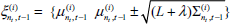
In our methods, the i-th new pose

EKF approximates the distribution through the first-order Taylor-series expansion of the nonlinear observation function zt=g(θ
nt
, st) around the mean

The first-order mean and covariance used in the EKF is given by Deterministically generate 2L+1 sigma points Si={Xi, Wi}:
Propagate the sigma points through the nonlinear transformation:
Compute the mean and covariance as follows:


Now we follow UKF algorithm to extend the path st,(i) by sampling the new poses Calculate the sigma points according to Eq. (4):
Using motion model to predict:
Incorporating new observation zt, along with the landmark nt:
Sampling new pose


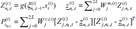
In this step, we update the posterior over the landmark estimates represented by the mean

The probability Calculate the sigma points:
Using observation model to compute the mean and covariance of the observation as follows:
Under this approximation, the posterior for the location of landmark nt is indeed Gaussian. The new mean and covariance are obtained using the following update:

Next, we resample from temporary particles set Št, then form the new particle set St. The necessity to resample arises from the fact that the particles in Št do not yet match the desired posterior. Resampling can avoid particles degeneracy. By weighing particles in Št, and resampling according to those weights, the resulting particle set indeed approximates the target distribution. To determine importance weight of each particle, it will prove useful to calculate the actual proposal distribution of the path particles in St. Under the assumption that the set of path particles in St-1 is distributed according to p(st-1 | zt-1, ut-1,nt-1), path particles in Št are distributed as:

Target distribution p(st,(i) | zt, ut, nt) takes into account the measurement zt along with the correspondence nt. The importance weight of resampling process accounts for the difference of the target and the proposal distribution, which is given by the quotient of the target and the proposal distribution, applying Bayes rule and Markov assumption and omitting the irrelevant variables:

To calculate

After the resampling, all particle weights are then reset to
SIFT Feature Extraction
The Scale Invariant Feature Transform (SIFT) was proposed in (Lowe, 2004) as a method of extracting and describing key-points, which are robustly invariant to common image transforms. The SIFT algorithm has four major stages: 1) Scale-space extrema detection. The first stage finds scale-space extrema located in Difference of Gaussians (DOG) function D(x, y,θ), which can be computed from the difference of two nearby scaled images separated by a multiplicative factor k:

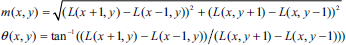

Maxima and minima are detected by comparing a pixel (marked with X) to its 26 neighbors in 3 × 3 regions at the current and adjacent scales (marked with circles).

A key-point descriptor.

Typical extracted SIFT features with their locations represented by ‘+’. The radius of the circle represents their scales: the 320×240 pixel test image taken at (a) 1618mm; (b) 756mm; and the result is (a) 278 key-points; (b) 267 key-points.
4) Key-point descriptor. Typical key-point descriptors use 16 orientation histograms aligned in a 4 × 4 grid. Each histogram has 8 orientation bins each created over a support window of 4 × 4 pixels (Fig. 3). The resulting feature vectors are 128 elements with a total support window of 16 × 16 scaled pixels. For a more detailed discussion see (Lowe, 2004). The number of features generated is dependent on image size and content, as well as algorithm parameters. In this paper, we use the vectors with 128 elements as key-point descriptor. Fig. 4 shows an example of SIFT feature extraction for a cluttered and occluded image of size 320×240 pixels.
This section describes KD-tree algorithm for determining the matching SIFT features pairs of successive images captured at relatively close positions along the robot's path by a monocular vision system mounted on the robot. Every time the CCD camera vision system is triggered, it captures the consecutive digital images of pixels and after SIFT feature extracting, generates SIFT feature match pairs in adjacent images through KD-tree based feature matching algorithm. The match pairs are used for the landmarks' 3D structure. Given a SIFT key-points set E, and a target key-point vector d, then a nearest neighbor of d, d′ is defined as:

After constructing the KD-tree, the nearest neighbor search algorithm which is depth first is used to search the child node which contains the target. The space occupied by set E is represented by a hyper-rectangle composed of two arrays: one of its minimum coordinates, the other of its maximum coordinates. To cut the hyper-rectangle, so that one of its edges is moved closer to its centre, the appropriate array component is altered. To check to see if a hyper-rectangle hr intersects with a hyper-sphere radius r centered a point target, we find the point p in hr which is closest to target. Write

The object intersect only if the distance between p and target is less than or equal to r.
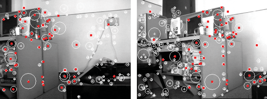
The SIFT feature matches based on KD-tree, and the matching pairs are represented by red “.”.

The key-point descriptor histograms of the matching key-point at different scale and direction.
We implement the SIFT key-points matching algorithm based on nearest neighbor algorithm in a KD-tree, and the distance of the key-points is represented using the Euclidean distance between their according 128 dimensional descriptor vector. The basic process for matching is as follows: A KD-tree is constructed using all key-points of the image It. For each key-point kp in the next image It+i, finding the two most nearest neighbors kp1 and kp2 based on nearest neighbor algorithm in a KD-tree. As proved in our experiment, if


Two viewpoints geometry and the epipolar constraint.
After the SIFT feature matching, we obtain the 2D SIFT image feature matching pairs used to structure the 3D spatial landmarks, which are in a single world model. As seen from Fig. 7, According to the epipolar constraint, all the entities P, O1, O2, p1, p2, e1, e2, b should be coplanar. Through epipolar constraint, the matches with large error are eliminated. Let/be the focus of the CCD camera. The relationship between a 3D point P(Xw, Yw, Zw) and the image coordinates p(u, v) where it is projected is given by the pinhole camera model (Ma & Zhang, 1998):


The solution of three unknown variants Xw, Yw and Zw can be obtained through the least square method.
The experiments are performed on a Pioneer 3-DX mobile robot incorporating an 800 MHz Intel Pentium processor as shown in Fig. 8(a). Motor control is performed on the on-board computer, while a 2.6GHz PC connected to the robot by a wireless link provides the main processing power for vision processing and the SLAM software. A monocular color CCD camera mounted at the front of the robot. The test environment is a robot laboratory with limited space as shown in Fig. 8(b).

(a) Pioneer 3 robot; (b) experiment enviroment.

Frames of an image sequence with SIFT features marked: (a) 2th frame; (b) 9th frame; (c) 19th frame; (d) 70th frame; (e) 79th frame; (f) 100th frame; (g) 150th frame; (h) 163th frame; (i) 172th frame.
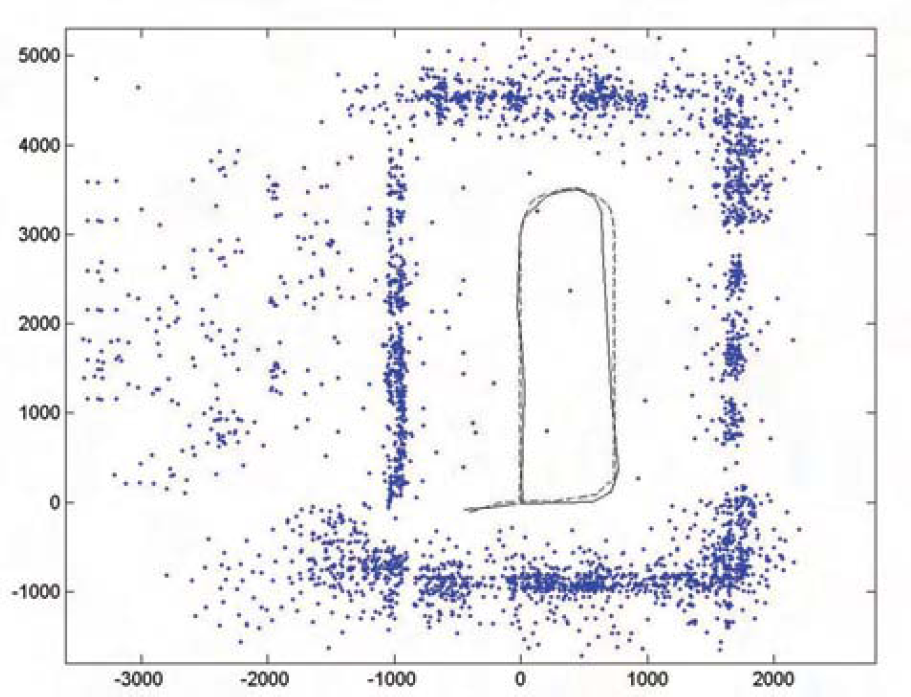
Bird's-eye view of the SIFT landmarks in the map. the dashed line indicates the estimated robot path and the solid line indicates the real robot path.

The 3D SIFT landmark database map viewed from different angles. Each landmark has appeared consistently in every view: (a) from top; (b) from left; (c) from right.
The images are captured and processed, the map is kept and updated on the fly while the robot is moving around. The robot goes around in the laboratory for one loop and to come back. Fig. 9 shows some frames of the 320 × 240 image sequence (189 frames in total) captured while the robot is moving around. A total of 4068 SIFT landmarks with 3D positions are gathered in the map. The runtime of our RBPF SLAM algorithm with different numbers landmarks is shown in Fig. 10. Other performance of our SLAM algorithm with different numbers of particles and landmarks is also shown in Fig. 12. Fig. 10 shows the bird's-eye view of all these landmarks. Fig. 11 shows three views of the 3D SIFT landmark map from different angles. Finally, we compare our method with traditional EKF method, and our method shows superior performance as shown in Fig. 13.

Performance of our RBPF SLAM algorithm: (a) robot position error and (b) landmark error with different numbers of particles; (c) runtime and (d) memory requirement with different numbers of landmarks.

Comparison of our RBPF SLAM algorithm and EKF for (a) robot position error and (b) memory requirement.
Novel RBPF is presented to implement monocular vision-based mobile robot SLAM in indoor environment. The particle filter is combined with UKF to sampling new poses integrating the current observation. The landmark position estimation and update is implemented through the UT and EKF respectively. For solving the particle depletion problem, the number of resampling steps is selected adaptively. Single camera tracks the 3D natural point landmarks, which are structured with matching feature pairs extracted through SIFT. The matching for highly distinctive SIFT features descripted with multi-dimension vector is implemented with a KD-Tree in the time cost of O(log2 N ). Experiment results show superior performance for our method.