
Abstract
A millimeters size omni-directional mobile micro-robot is presented in this paper. A unique duel-wheel structure is designed for no-slip motion during the steering, by turning the slip friction between the wheel and ground into rolling friction. The robot was driven by four electromagnetic micromotors with 2.1mm×2.1mm×1.3mm size. Three of them are for translation and the other one is for rotation. Kinematics model is analyzed to prove the omni-directional mobility. Virtual-Winding Approach (VWA) and PWM-Based Vector-Synthesize Approach(PBVSA) current control methods are presented to satisfy a requirement of higher positioning accuracy. Experimental results demonstrate the feasibility of this concept.
Introduction
The development of micrometer cube micro-robots has recently received much attention. The environments in which these robots supposed to operate are narrowed and potentially extra-complicated space, such as microfactory, blood vessel, and micro-satellite. The robot must have omni-directional mobility, high power and high load capacity, within micrometer cube volume, in order to accomplish the work efficiently.
Some researchers started to build micro-robots driven by different principle. The microprocessor and Interface Lab of EPEL has developed a 1cm3 car-like micro-robot with two Smoovy 3mm motors. R.H. Byrne and D.R. Adkins developed a 4cm3 volume and 28g weight micro-robot for plume tracking with two Smoovy micromotors (R.H. Byrne et al, 2002), with a car-like steering. James McLurkin designed Ants micro-robot with a 36.75cm3 volume and 33g weight, driven like a tank with pedtail(J. McLurkin, 1998). Caprari and Balmer built another car-like micro-robot with 8cm3 volume by watch motor(G. Caprari et al, 1998). Dario developed a millimeters size micro-motor by a novel type of electromagnetic wobble micromotor, with a three-wheel structure (Dario P. et al, 1998).
Several research groups are developing omnidirectional mobile robot due to inherent agility benefits(Robert L. Williams et al, 2002). These can be broken into two approaches: special wheel designs and conventional wheel designs. Fujisawa et al., Ferriere and Raucent developed the universal wheel for omnidirectional mobility (Fujisawa, S. Et al 1997)(Ferriere, L. & Neuman, C.P., 1998). Muri and Neuman developed the Mecanum wheel similar with universal one(Muir, P.F. et al, 1987). West and Asada developed the ball wheel(West, M. & Asada, H, 1997), while Killough and Pin developed the orthogonal wheel(Killough, S.M. & Pin, F.G., 1994).
These special wheels designs are demonstrated good omnidirectional mobility, however, they generally have complex mechanical structures. Other researchers tried to develop the omnidirectional vehicle by conventional wheels. Boreinstein, et al, designed the omnidirectional structure using steered wheels(Boreinstein, J. et al, 1996), while Wada and Mori using active castor wheel(Wada, M., and Mori, S, 1996).
Mobile micro-robot and Omnidirectional mobile robot were well developed recently. However, few Omnidirectional mobile microrobot has been reported. Special wheels developed are very difficult to realize in micrometers size due to their complexity. Further, these structures have limited load capacity with slender rollers. Traditional wheels are the possible solution for omnidirectional mobile microrobot within 1cm3 volume, due to their inherent simple structure. However, the micro actuator within 10 mm3 with high power output is still a challenge at present.
This paper presents an omnidirectional mobile microrobot by novel electromagnetic micromotors, which has an original duel-wheel structure within 1cm3 volume. This paper was motivated by a need of microfactory transport mission, which necessitated development of a high precision omnidirectional micro-robot.
This paper first presents our omnidirectional mobile micro-robot design, followed by kinematics analysis, then a control method to realize high precision, and experimental results to demonstrate omnidirectional mobility.
Design of omnidirectional mobile micro-robot
Novel duel-wheel structure design
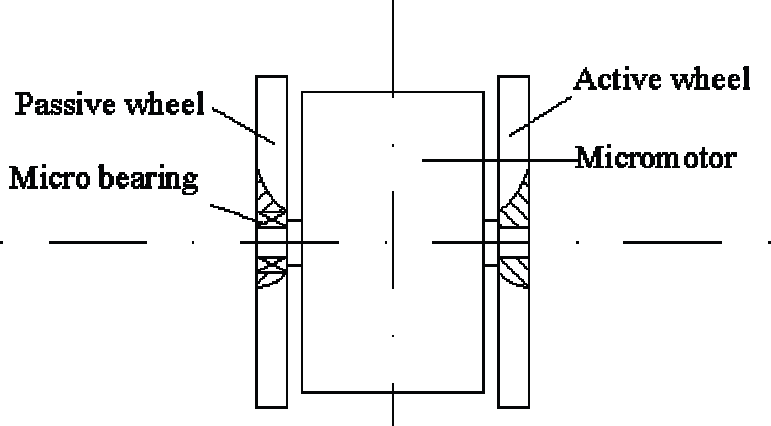
The novel duel-wheel design composed of two coaxial traditional wheels, which are separated at a distance, driven by electromagnetic micromotors, as shown in Fig. 1. The unique character of this design is the duel wheels are driven by one motor and by friction force independently, instead of being driven two motors. This motivation is driven by scaling the robot volume into 1cm3, while giving it the omnidirectional mobility, high load capacity and high positioning accuracy.
Structure of novel dual-wheel
This novel duel-wheel structure has certain advantage over single wheel designs and the normal duel wheels. Designs using conventional single wheel produce high friction and scrubbing during the steering as the wheel is actively twisted around a vertical axis. This causes a slip motion and reduces positioning accuracy and increases power consumption, which is especially important for a micro-robot. The scrubbing problem can be reduced using the duel wheels. However, in normal duel wheels structure, both wheels are driven by two independent motors, which increase the complexity and the size of the structure.
The novel structure is to change the scrubbing torque between the duel-wheel structure and the ground into rolling resistance during its steering, keeping the small volume as well. Two coaxial wheels, named active wheel and passive wheel, are connected to one micromotor shaft on both sides. The active wheel is fixed to the shaft, driven by micromotor. While the passive one has the rotary freedom around the shaft of the micromotor, driven by friction force between itself and the ground. Therefore, the wheels are always rolling even during steering, which keeps the pose of micro-robot chassis. The active wheel and the passive wheel rotate synchronously due to friction during translation. In contrast, the two wheels rotate with opposite directions. This structure is designed to achieve omnidirectional mobility with reduced wheel scrubbing, in limited volume.
Actuators are one of the major problems in designing micro-robots. The main reason is lack of available micromotors and poor performance of the existing ones. Several forces, including electrostatics, piezoelectricity hydraulics, pneumatics, and biological forces scale well into the micro domain. However, some of them are very difficult to build in small size. Electromagnetic forces can bring the micro motor larger output torque(R.S. Fearing, 1998) and longer operating lifetime in the same volume than others. The electromagnetic micromotors developed (such as smoovy micromotor and IMM micromotor) are design with radius flux structure, which bring the micromotor with a height a few times as its diameter. In this paper, an axial flux original electromagnetic micromotor is designed (shown in Fig. 2) with the following characteristics:

2mm axial flux electromagnetic micromotor
A novel structure in which the rotor is set between the two stators
The axial magnetic field shrank the volume of micro-robot.
The stator has multiple layers slotless concentrated planar winding.
The rotor has multi-polar permanent magnet with high performance.
The parameters of electromagnetic micromotor is designed and optimized by genetic algorithms (Zhenbo Li and Chen Zhang, 2000). According to the results of optimal design with GA, a stator winding of electromagnetic micromotor with 2mm diameter is manufactured by the micro-fabrication techniques. A stator winding which is composed of 6 layer coils, 42 turns and 9 pairs, its diameter is only 2mm and minimum line space is 1μm. the maximum operation current of coils is 230mA and resistor is 22–30Ω. The structure of the winding is shown as figure 3.

Structure of the stator
The rotor was made from SmCo permanent magnetic alloy. Special magnetization method was employed to write pairs of magnetic poles on the surface of rotor in the vertical direction. The performance is shown in Table 1.
Main performance index of micromotor

The omnidirectional micro-robot consists of three special castors composed of two coaxial normal wheels, which are separated at a distance, driven by electromagnetic micromotor, connected with each other by a set of gears, as shown in fig. 4. The set of gears are fabricated by LIGA process and have gear ratio of 1/3. The micro-robot is driven by four electromagnetic micromotors. Three of them are for translation movement, while the other one is for rotation movement. The active gear driven by steering micromotor is in the middle of the chassis. The other three gears are connected to the duel-wheel structures through axis perpendicular to the chassis plane. Power from the micro motor is transmitted through gears to the axis, and then to the duel wheels via friction between the wheels and the ground. Therefore the three structures will keep the same direction at every moment. The translation driven motors are controlled as one motor to rotate synchronously.
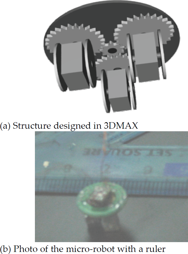
Structure and photos of the omni-directional micro-robot
Besides transmitting steering power, the set of micro gears amplify the rotate driving power and improve the rotary positioning accuracy of the micro-robot in the meanwhile.
The photos of omni-directional mobile micro-robot are shown as Fig. 4(b). It has a size with 9.8mm×9.8mm×6mm.
The structure of the novel duel-wheels is shown as Fig. 1. The active wheel is fixed to the micromotor shaft, while the passive wheel has the rotary freedom around the shaft. When the duel-wheel turns, the vertical shaft (transmission gear shaft) doesn't move. Therefore we can simplify the complicated wheels as a single virtual wheel locating in the center of the duel-wheel with zero thickness, which is drawn on Fig. 2b as the broken line. In the coordinate systems defined in Fig. 5.

Coordinate systems of a dual-wheel
Cr = (Or, Xr,Yr, Zr) is the robot inertial coordinate frame
C0 = (O0, X0, Y0, Z0) is the ground inertial coordinate frame
ψ the angle which Cr offset C0
xak x Coordinate of the point the Kth active wheel contacting with ground
yak y Coordinate of the point the Kth active wheel contacting with ground
xpk x Coordinate of the point the Kth passive wheel contacting with ground
ypk y Coordinate of the point the Kth passive wheel contacting with ground
xk x Coordinate of the point the Kth virtual wheel contacting with ground
yk y Coordinate of the point the Kth virtual wheel contacting with ground
θk (t) Rotation angle of the Kth virtual wheel from the vertical axis at time T
φk (t) Rotation angle of the first virtual wheel from the horizontal axis at time T
Since the micro-robot moves on a plane, the coordinate Cr is chosen to satisfy the analytic requirement. Therefore, the pose vector ζ consists of the Descartes coordinate of the reference point Qr in coordinate C0 and the offset angle Cr from C0.
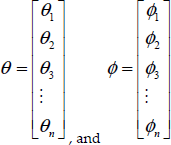
Because the micro-robot carried by the novel duel-wheels moves on a plane, its motion has three degrees of freedom. Assume that the micro-robot consists of n novel duel-wheel structures, therefore, we can express the micro-robot state (s) with 3+2×n vectors:

Where
While the micro-robot moves, the wheels only roll on the plane without slip. The velocity of the contact point between the virtual wheel and ground is zero.


Therefore, the steering motion of the micro-robot and the angle velocity of the virtual wheel can be drawn as following:


The micro-robot kinematics constraints can be expressed by considering the two novel duel-wheels.


where
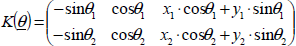


Assume A(s) express the constraints matrix of micro-robot kinematics, therefore,

The kinematics constraint equation is

The kinematics of the omni-directional micro-robot is to analyze the possible mobility under the kinematics constraint equation (11).
The Mobility
From the equation (5), the state vector 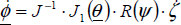
Therefore, the zero space of
Assume the turning angle the micro-robot is fixed, the matrix
After that, the micro-robot is proved to have only one freedom when it moves around the plane.
Under the constraint of equation (5), the directionality is defined to the micro-robot movement when the vector
The angle of the micro-robot to the frame 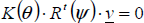
It proves that the micro-robot can achieve omnidirectional mobility under the kinematics constraint of equation (5).
Load capacity and positional accuracy are both key factors for robots to decide their application fields. Control of robot is equal to control of its drivers. Macro robot usually adopts the step motor as its driver, which realized the positional accuracy by the mechanical structure. Typically, a step motor is driven by six-step commutation. The conducting interval for each phase is 120° by electrical angle. The commutation phase sequence is like A-AB-B-BC-C-CA. The output torque of the step two phases conducted current is equal to the step only one phase conducted current. However, the output torque can be increased by improve the current in the phases, since the windings is permitted with high value current. In contrast, the micro-robot adopts micro motors as its driver, which is now impossible to process the same structure as macro step motor. Therefore, control approach is the only way to improve output torque and positional accuracy of micro-robot.
The micromotor designed in this paper has 8 polar on its rotor and 6 coils on stator, and is designed as a 3-phase synchronous motor, with the star-connected windings. Therefore, the micro-robot can move either fast or step-by-step, to satisfy different application requirements. The micromotor can be controlled with two approaches, 2–2 phases conducted approach (2–2 PCA) and 3–3 phases conducted approach (3–3 PCA). 2–2 PCA means only two phases conduct current at any time, leaving the third phase floating (vector figure is shown Fig. 6(a), AB̅ represents that current in windings is from A through middle point to B), while 3–3 PCA means all the three phases are conducted. In order to produce maximum torque, the inverter should be commutated every 60° by electrical angle. Therefore the micromotor need change 6 steps (Fig. 6(b)) rotating in 360° by electrical angle, while 24 steps in mechanical 360°. The micro-robot can move at a speed from 0 to 10cm/s controlled as a synchronous motor. At the same time, since the wheels of micro-robot are 3.3mm and the gears ratio is 1/3, the micro-robot has a positioning accuracy of 0.43mm/step(πD/24) in translation movement and 5°/step(360/(24*3)) in rotary movement, without output torque ripple, in such two control approaches.

Vectors in an electrical angles 360°
Such accuracy is not higher enough for the mission in micro field, for example, in micromanipulation. Novel approaches, Virtual-Winding Approach(VWA) and PWM-Based-Vector-Synthesize Approach(PBVSA) is designed to improve the output torque and positional accuracy of a electromagnetic asynchronous micromotor, without changing its structure. VWA is for 2–2 PCA and PBSVA is for 3–3 PCA.
Both the two approach are to control the value and direction of current in each phase, then to change value and direction of synthetical magnetic, therefore increase the steps of micromotor in 360° by electrical angle. The VWA is realized by connected the central point of the phases with a virtual winding (named as R') controlled by PWM signal, shown in Fig. 7. The average value of virtual coil was selected by changing the frequency of PWM pulse, to change the current value of each phase. In this approach, 72 steps in 360° by mechanical angle were realized by inserting two steps into one step in 2–2 PCA. The virtual windings value is supposed x times as the single phase resistor value, then the communication phases sequence is like:


Virtual coil principle for current divided
In contrast to 2–2 PCA, There are 2 new steps with VWA in a control step (are shown in Fig. 8), which means in 60° by electrical angle. Therefore the positional accuracy of the micro-robot is equal 3.14×3.3/72=0.143 mm/step, and the rotary accuracy is 1.667°/step.

Virtual coil control for step precision increasing
Figure 9 shown the experiments waves which the micromotor under 2–2 PCA control and virtual coil control. The black bumps in Fig. 9(b) wave are the voltage wave of the inserted steps. In theory, the even higher accuracy can be achieved in this approach. However, the approach has a disadvantage, which the virtual windings reduces the output torque, which weaken the performance of the micro-robot.
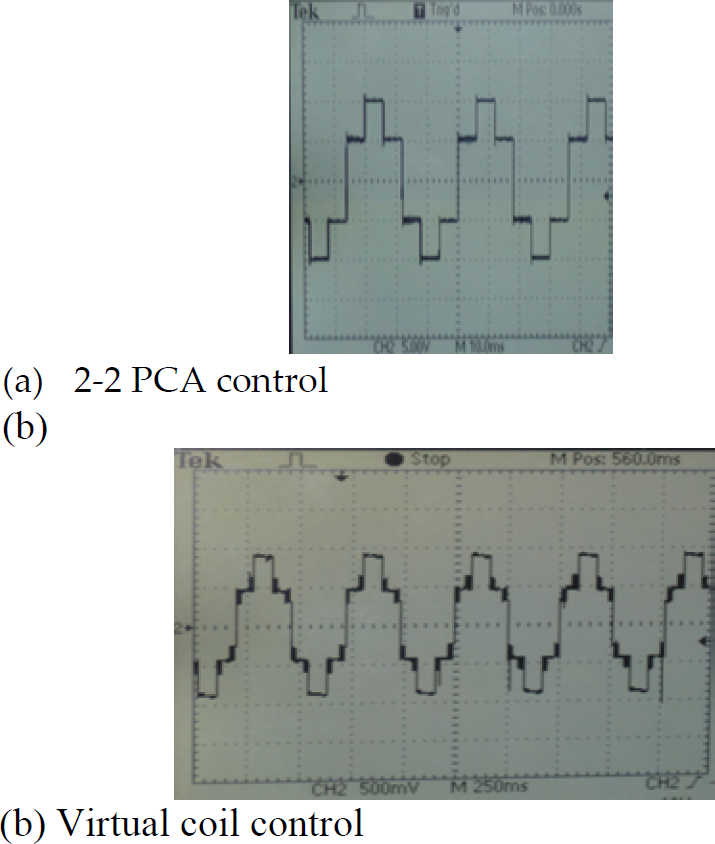
Voltage waveform of micromotor under 2–2 PCA control and VWA control
PBVSA is realized under 3–3 PCA control, by utilizing the third coil of the micromotor to dividing charge into two parts to synthesize the magnetic to insert steps required, since the three windings are star-connected. Two circuits are conducted alternately at high frequency realized by two PWM signals. The vectors in a 3–3 PCA step are shown in Fig. 10. Assume the windings are conducted with AB̅ and B̅C by two different PWM signals at this moment. By changing the ratio between the two circuits conducted time, the current values in the three windings can be changed as the requirement, then the different directional synthetical torque with constant value were obtained. Usually the frequency of PWM signal is at least ten times as the one of commutation.
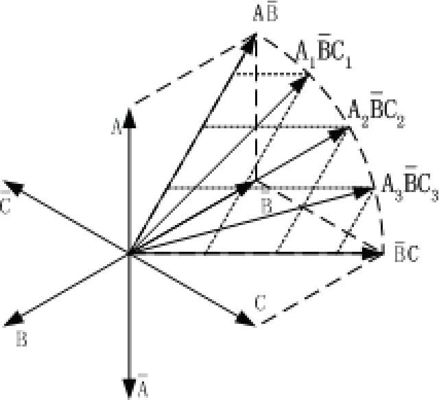
Commutation vectors under current control for microstepping
Microstepping of a star-connected PM micromotor is realized with constant torque, without any additional circuit. Therefore the efficiency is high. Experiments that at present 144 steps is realized under PBVSA control. The control waves, phase voltage changing relative to ground and the amplified part, are shown in fig. 11.

Waves of voltage between coil conducted and ground under 3–3 PCA control and PBVSA control
In this paper, an original omni-directional mobile microrobot design is presented. It is based on a novel duel-wheel structure and a new electromagnetic micromotor design. Each duel-wheel unit has two coaxial wheels, one of which is active driven by micromotor, and the other driven by the friction between the wheel and the ground. This design offers some advantages for micro-robot to be realized over existing omni-directional structure—simple mechanical structure, high loading capacity and slip-free motion. It brings the micro-robot lower wheel scrubbing resistance than conventional structure. This means higher power efficiency and higher motion precision. The results demonstrate that the micro-robot driven by electromagnetic micromotor has omni-directional mobility, enough load ability, controlled velocity and high motion precision.
Footnotes
Acknowledgements
This work was supported by the China NSFC.