
Abstract
People who suffer from hearing impairment caused by illness, age or extremely noisy environments are constantly in danger of being hit or knocked down by fast moving objects behind them when they have no companion or augmented sensory system to warn them. In this paper, we propose the General Moving Object Alarm System (GMOAS), a system focused on aiding the safe mobility of people under these circumstances. The GMOAS is a wearable haptic device that consists of two main subsystems: (i) a moving object monitoring subsystem that uses laser range data to detect and track approaching objects, and (ii) an alarm subsystem that warns the user of possibly dangerous approaching objects by triggering tactile vibrations on an “alarm necklace”. For moving object monitoring, we propose a simple yet efficient solution to monitor the approaching behavior of objects. Compared with previous work in motion detection and tracking, we are not interested in specific objects but any type of approaching object that might harm the user. To this extent, we define a boundary in the laser range data where the objects are monitored. Within this boundary a fan-shape grid is constructed to obtain an evenly distributed spatial partitioning of the data. These partitions are efficiently clustered into continuous objects which are then tracked through time using an object association algorithm based on updating a deviation matrix that represents angle, distance and size variations of the objects. The speed of the tracked objects is monitored throughout the algorithm. When the speed of an approaching object surpasses the safety threshold, the alarm necklace is triggered indicating the approaching direction of the fast moving object. The alarm necklace is equipped with three motors that can indicate five directions with respect to the user: left, back, right, left-back and right-back. We performed three types of outdoor experiments (object passing, approaching and crossing) that empirically verified the effectiveness of our proposed algorithm. Furthermore, we analyzed the time and direction response based on neck vibrations. The statistical analysis (including hypothesis test) suggests that the chosen alarm necklace can provide a rapid indication for a quick human response.
Keywords
1. Introduction
1.1 Background
Wearable haptic devices measure the state of the environment or of the human itself (with sensors) and provide the user feedback from the measured information (with actuators). These types of devices have a wide range of applications, most of which are targeted at building systems for aiding and rehabilitating elderly and disabled individuals. For example, Lee et al. built a haptic master system for physically disabled people, which can provide contact force by detecting the human shoulder movement [1]. Kayyali et al. developed a Cyber Force System to generate a force field to achieve daily motor rehabilitation [2]. Vaucelle et al. focused on touch therapy and made a couple of haptic interfaces (such as Touch Me, Squeeze Me, Hurt Me, Cool Me Down, etc.) for health care [3]. In this paper, we focus on aiding the mobility and independence of people with hearing impairment caused by illness or the deterioration of the hearing and visual senses due to age.
Persons with these types of disabilities face the challenge of learning how to move about in the world as freely and independently as possible. Taking on this challenge without a companion is a somewhat dangerous task, for example, when trying to walk outside on their own. This is particularly true when objects (humans, vehicles, etc.) move behind them, and the situation can be very dangerous for elderly people. A similar situation exists not only for the elderly or other people with hearing impairments, but also for people in extremely noisy environments such as construction sites. In order to aid these people with their mobility and avoid accidents under such circumstance, we propose a practical wearable haptic system: the General Moving Object Alarm System (GMOAS). The GMOAS monitors the motion of moving objects behind endangered people with a laser range sensor and alerts them by providing a special vibration signal to his/her neck.
Tactile vibrations have been recently used in systems that aid the hearing/visually impaired in their everyday life. For example, the V-Braille system introduced by Jayant et al. uses the vibrations and touch-screen on a mobile phone to haptically represent Braille characters for the deaf and blind [4]. Many assistive technology companies have launched vibration-based products for the deaf, hearing impaired, blind, low vision and physically challenged. These include vibrating watches developed by Assistech, and vibrating alarm clocks and bed vibrators developed by Harris Communications [5, 6]. In a similar way to these products, which represent characters and events with vibrations, we represent approaching objects by modulating vibrations in a necklace that indicates the general direction from which the object is moving towards the user.
The proposed General Moving Object Alarm System is composed of two main subsystems: a moving object monitoring subsystem (the sensory component based on laser range data) and the alarm subsystem (the feedback component based on tactile vibrations to the neck of the person).
1.2 Moving Object Monitoring Subsystem
For the moving object monitoring subsystem, we propose and evaluate empirically a computationally efficient method for detecting moving objects, monitoring their trajectories/approaching speed, and detecting where the approaching object is potentially dangerous.
Existing research on laser range-based motion detection and tracking has been focused mainly on human detection and tracking [7, 8] which has shown to have great relevance in surveillance applications [9, 10], as well as sports [11] and human-robot interaction [12]. In our research, we focus on evaluating a general approach that can handle any type of moving object, especially fast moving objects, and which is computationally efficient. Furthermore, our method can simultaneously track a number of different types of targets (like human, vehicle, etc.) in a given scene.
The key issues in this detection and tracking problem include object segmentation/association [13, 14] and object tracking. As the measurements obtained from laser range sensors are a series of points, it is necessary to segment these points into clusters to differentiate and track the various objects. The spectral clustering algorithm has become a popular approach to segment range data, due to its power of maximizing connectivity within clusters and minimizing the connectivity with different clusters. This connectivity is evaluated using a scaling parameter, a common measure of similarity. Ng el. firstly proposed a method to automatically calculate the best value for the scaling parameter [15]. Zelnik-Manor and Perona analysed the eigenvectors of the normalized affinity matrix by minimizing the cost function using gradient descent [16]. Although these methods are very powerful, the computational burden is huge.
The other key issue is object tracking. A common approach used in the literature for object tracking is to use optimal estimation. Schulz et al. used particle filters to track moving objects [17]. Tao et al. proposed a sampling algorithm to track multiple objects [18]. Bobruk and Austin applied a Kalman filter to estimate the velocity of objects [19]. The method series of optimal estimation can have a very good performance, but it also takes much time to get the optimal tracking results.
1.3 Alarm Subsystem
We choose to use vibration as an alarm signal for the GMOAS. To identify the approaching direction of the fast moving object, we provide five resolutions as left, back, right, left-back and right-back. The vibrations are produced by a mini-motor. The key issue is to choose a part of the human which is very sensitive to vibration. This tactile sensitivity issue has been researched for many years. Initially, researchers addressed the basic physiology of the skin [20, 21], such as fibre classification [20, 22, 23], absolute threshold [23–25], adapting analysis [26], etc. Afterwards, research was focused more on tactical sensitivity. Weber touched various areas of skin and compared tactile sensitivity for a particular body site compared with all the other body sites [27]. Weinstein compared the difference of tactile sensitivity for gender and for the left and right sides of the body. The result is that for pressure sensitivity, women are more sensitive than men. Sensitivity is generally the same for both the left and right sides of the body [28]. Wilska placed a vibrator (driven by a sinusoidal current) against skin on different areas of the body. The hands and soles of the feet are the most sensitive areas for vibration [29]. Furthermore, there have been studies showing the significant variability in vibration thresholds within a particular region among elderly and obese people [30, 31]. Stuart et al. found that younger subjects have higher sensitivity thresholds for the forearm, shoulder and cheek [32]. To conclude, Table 1 is from a technical report of an Army Research Laboratory on tactile sensitivity and human interfaces.
Body sites for tactile sensitivity measures [33]

As seen from Table 1, the most sensitive area for vibration stimulus are the hands and the soles of the feet. However, it is not convenient to place vibration actuators on these body parts. As the vibration sensitivity is relatively high in the larynx region and head region, we place the alarm actuator, i.e., vibration motors, around the neck region. As the neck is such a sensitive part of the body, it would sense the alarm of an approaching object more easily than in any other body part.
1.4 Paper Organization
In this paper, we developed a General Moving Object Alarm System (GMOAS) to monitor the approaching behavior of general objects behind a user, and quickly provide an alarm in the case where the situation is dangerous. In our method, continuous objects are detected with high efficiency. By updating a deviation matrix, the object association solution can also be quickly found. The alarm necklace is equipped with three motors indicating left, right, back, left-back and right-back directions. When the approaching speed is beyond a safety threshold, the alarm necklace is triggered, indicating the approaching direction of the fast moving object. Three categories of outdoor experiments were performed: objects passing, approaching as well as crossing, which empirically verified the effectiveness of the approaching speed monitor. Experiments and statistical analysis regarding the time and direction response of the neck vibration suggest that the alarm necklace can provide a rapid indication for a quick human response.
This paper is organized as follows. In Section 2, after describing the system architecture, we explain the approaching speed estimation method based on continuous object detection and their association. In Section 3, the GMOAS system is tested in angle/range tracking, approaching speed estimation and vibration response. Finally, we give the conclusion in Section 4.
2. Method
2.1 System Architecture
The equipment used in the GMOAS system includes a laser sensor and a special alarm necklace. The laser monitors the moving object behind the subject. When the approaching speed is beyond a safety threshold, the alarm necklace is triggered, indicating the approaching direction of the fast moving object (Fig.1).

Architecture illustration of the GMOAS system
The laser used is the LMS100 produced by SICK Sensor Intelligence. It repeatedly scans the environment in a counterclockwise direction and outputs range information for different angles in pairs. Its maximum radial range is 20m/18m (at 10% reflectivity), while its maximum angular range is 270°. It has two working modes, with either 0.5° or 0.25° angular resolution, and with 50Hz or 25 Hz scanning frequency. We chose the working mode as (50 Hz, 0.5°), given that speed is a requirement for our application. Thus, for each measurement taken in a certain moment in time (every 25msec), we have 541 samples corresponding to the range data for 0° to 270°.
The alarm necklace provides vibration indication to subjects. We use three motors on the alarm necklace placed strategically on the left side, back side and right side of the neck to indicate left, back and right respectively. In order to indicate left-back and right-back, both left and back, and right and back motors are stimulated. The three motors are driven by an Arduino, which is an open-source single-board micro-controller. The processor on the micro-controller is Atmel AVR and it can be programmed by Wiring-based language, similar to C++ with a little modification.
2.2 Continuous Object Detection
Since we focus on monitoring the speed of a moving object behind the user, the first step is to determine the range in which we should pay attention to. We set this range threshold as

where

Once the planar fan-shape occupancy grid is filled, we divide the laser measurements into different groups.
Each group represents a continuous object, the grouping is represented in a binary fashion, with “1” being a continuous object and “0” being no object. Based on the object detection above, we can get an object index vector with the following format
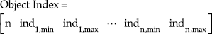
where n is the total object number.
2.3 Object Association
The laser scans the environment repeatedly at 50Hz. For each moment in time, we obtain a number of regions corresponding to objects through the continuous object detection method outlined above. A crucial issue however is to be able to identify the relation between adjacent moments in time. This answers the question: which regions detected in the previous moment in time correspond to the current detected regions? Of course, there is often more than one region detected. Moreover, the number of regions changes over time, as objects enter and exit the field of view of the laser. Thus, we perform region association across time frames, a process which is usually called object association. Fig.2 illustrates three basic states of object association, where the laser is in the centre, and the “0” or “1” values around the circular sector illustrate whether or not the corresponding sector of the fan-shaped grid is occupied.

Motion detection pattern. (a) Situation 1; (b) situation 2; (c) situation 3
In general, three distinct possible cases can occur during object association.
Case 1: The number of objects does not change, but their appearance does. For example, the object 1 in the previous scan (Fig.2 (a)) and the present scan (Fig.2 (b)) is the same object. But its position and orientation change.
Case 2: The number of objects changes. There are two possibilities for the number of objects changing: appearance and disappearance of objects. The first possibility is when an object is not present in the current scan but it appears in the next scan. For example, in situation 1 (Fig.2 (a)) and 2 (Fig.2 (b)) only object 1 is present, however in the next scan (Fig.2 (c)), object 2 appears. In the disappearance case, an example would be that in a further scan after situation 3, object 1 or 2 would no longer be present.
Case 3: Both the number, the identities, as well as the appearance of objects change. This is the most complex case: not only the objects change position and orientation, but also some objects appear and disappear with time.
The key point for the object association problem is to update a relation of object matching across consecutive time samples. Here, we consider three matching criteria for object matching: range deviation, angle deviation and size deviation. For each deviation, we built a deviation matrix as follows. Suppose we detect nj objects and nj+1 objects in two moments j and j+1. The deviation matrices' definitions are
where

for

It is noted that the deviation matrix Div is a square matrix only when the object number does not change for the two adjacent moments. We define a vector Ass to store the object association information. For an element
2.4 Approaching Speed Monitor
We monitor the moving speed of the object by tracking the range change of the centre of the object. Supposing the range of the centre of the object at the j-th moment is

If v̂app is larger than a safety speed threshold vapp,thr, we trigger the vibration system to alarm the subject, i.e.,

3. Result
3.1 Experiment Setting
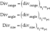
Three outdoor experimental sequences were conducted to evaluate the proposed approach: a passing experiment, an approaching experiment and a crossing experiment (Fig.3). Specifically, in the passing experiment, one subject moves from right to left; in the approaching experiment, one subject approaches the laser; in the crossing experiment, two objects move face-to-face, pass by each other, and move away from each other. These three experiments are the typical possible scenarios in practice. Complex scenarios are merely combinations of these three. Thus, we choose these three experiments to verify our algorithm. The trajectories of the moving objects in the three experiments are shown in Fig.4.
Experiment snapshots. (a), (b), (c) The passing experiment; (d), (e), (f) the approaching experiment; (g), (h), (i) the crossing experiment

Moving trajectory. (a) The passing experiment; (b) the approaching experiment; (c) the crossing experiment
3.2 Angle Tracking of the Objects
In these three experiments, we set rinterested as 6000mm, an acceptable initial distance taking into account the velocities of common moving objects and the reaction time of subjects. The number of the moving objects always changes between adjacent moments. In our experiments, the number of the moving objects changes from 4 to 14. Fig.5 gives the angle tracking of all the objects where (a), (c), (e) show the 3D grid matrix, and (b), (d), (f) show the contour of the corresponding 3D grid matrix.

Angle tracking of the objects. (a), (b) The passing experiment; (c), (d) the approaching experiment; (e), (f) the crossing experiment
The x-axis is the angle index from 1 to 541; the y-axis shows the time index of the time sample throughout the experiment; the z-axis is the occupation state for the 540 fan-shape grids. The motion of all the objects is accurately tracked and this can be seen clearly in the 3D grid matrix. It must be noted that four types of objects exist in this experiment: (i) a moving human, (ii) stationary objects (like tree trunks), (iii) environmental uncertain objects (like flying birds), (iv) noisy measurements from the laser sensor.
3.3 Range Tracking of the Moving Objects
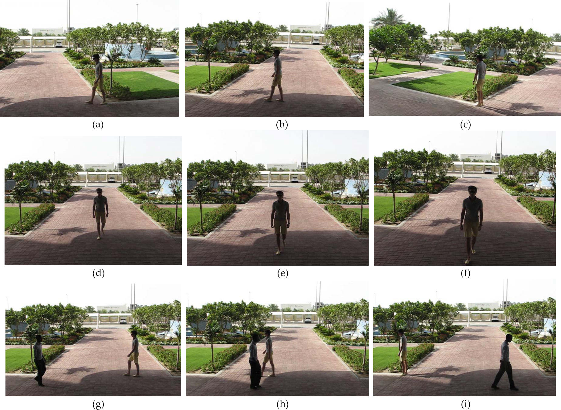
In these three experiments, we tracked the change in range distance of the moving objects (Fig.6) where the x-axis is the time index and the y-axis is the range data. In the passing experiment, as the subject moves from right to left, the trajectory is approximately a straight line. Thus, the range reaches a minimum distance at about the intermediate position of the trajectory (a). In the approaching experiment, the subject starts to move at about the 15-th moment and stops at about the 50-th moment. The total moving distance is about 3000 mm (b). In the crossing experiment, for each subject, the basic moving pattern (i.e., curve shape of range) is the same as that in the passing experiment. However, as the two subjects need to avoid collision between each other, they slightly change moving trajectories ((c) and (d)).
Range tracking of the moving object. (a) The passing experiment; (b) the approaching experiment; (c), (d) the crossing experiment
3.4 Approaching Velocity Monitor of the Moving Object
Based on the range tracking and angle tracking, we monitor the approaching velocity of the moving objects. In this research, we set the approaching velocity to trigger the alarm as 3m/s. Hence, vapp,thr = −3000 mm/s. The monitoring results of the passing and approaching experiments are shown in Fig.7. The range information obtained from the laser sensor contained noisy measurements, so we used a simple IIR low-pass filter to remove these disturbances.

Approaching velocity monitor. (a) The passing experiment; (b) the approaching experiment
3.5 Vibration Response Analysis
As the studies previously presented show that sensitivity is generally the same for both the left and right sides of the body [28], we do not consider this issue in this paper. Instead, we focus two other important issues: direction-response and time-response. There are in total 24 subjects from 12 countries participating in the experiment. We divided all the subjects into two groups: male group (12 subjects: 33.6±7.0 years old; 175.4±6.1cm height; 71.1±12.7kg weight) and female group (12 subjects: 26.6±4.5 years old; 160.3±10.6cm height; 56.4±11.3kg weight). For each group we applied the following basic procedures in vibration response analysis, including:
Stimulate the subject with vibrations on the left, back, right, left-back and right-back directions. Meanwhile, we communicate to the subject the generated stimulus direction and the subject must press the respective button on the real testing phase. When the subject is familiar with the vibration system, we begin the real test;
The system randomly triggers the vibration necklace in the five directions mentioned earlier. The subject presses one of five buttons to respond. The system automatically records the direction and time response. The total time for the experiment is approximately 2 min;
Apply statistical analysis on the experimental data and compare the response in male group and female group.
In Fig.8, the vibration direction is denoted in the rule: M-male group, F-female group, L-left, B-back, R-right, LB-left back, RB-right back. Before processing T-Test, the normality of the experiment data was tested by the Shapiro-Wilk test.
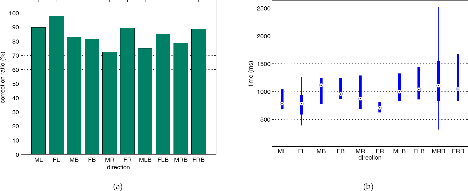
Vibration response comparison. (a) Correction ratio of the direction-response; (b) time-response of the male and female group in 5 vibration direction
For direction response, Fig.8 (a) shows the correct direction response ratio in percentage where the x-axis denotes the directions and y-axis denotes the percentage of the correct response in direction. It is clear that both the male and female groups have a high accuracy in direction response (normally more than 80%). In addition, based on the T-Test, the female group has an higher accuracy in direction recognition than the male group in the right direction (p=0.08).
For time response, we give the statistical result of the response time in 5 directions respectively (Fig.8 (b)) where the x-axis denotes the vibration directions, the y-axis denotes the response time. Here, the central mark is the median. The edges of the box are the 25th and 75th percentiles. The line outside of the box shows the boundary of the measured data. However, as it is beyond approximately +/–2.7σ range (i.e., 99.3% coverage in probability), we can consider them as abnormal response events. In the experiment, this usually corresponds with the initial response when the subject is not used to the vibration stimulus. It is shown that both the average response time and the variance range are small, indicating the effectiveness of the developed system. Additionally, the T-Test result shows that the female group has a shorter response time in the right direction (p=0.01).
Regarding the comfort issue of the alarm necklace, compared with men, women felt more comfortable with the alarm necklace because they are used to having accessories around their necks. Some of the subjects thought that the alarm necklace felt a little tight when wearing.
3.6 Discussion
From the above results on the tracking performance and vibration response, the GMOAS is verified for functionality. However, as it is still a prototype, the system can be improved towards comfort. First of all, the laser used in this research weighs 1.1kg. This is too heavy for everyday use and a lighter version of the laser can replace the existing one. Additionally, the alarm necklace is made out of nylon which makes the necklace feel tight on the neck, a more comfortable material can used instead. Third, a main circuit for computation and control is desirable to make the whole system compact for movable usage.
4. Conclusion and Future Work
Motivated by the need for preventing collisions with objects approaching humans from behind who are elderly, hearing-impaired, or in noisy environments, we created a system based on a laser ranging sensor and a haptic buzzer neck-mounted alarm. In this paper, we described an efficient yet highly effective algorithmic solution for detecting moving objects and tracking their approaching behaviour, in order to appropriately trigger the alarm in the case of impending danger. In this research, we do not focus on tracking all moving objects on a very large scale, but only focus on its approaching behaviour in a certain scope, dictated by requirements regarding safety. We illustrated how the object segmentation and association can be solved based on fan-shaped grids. The proposed object association is a local optimal algorithm, and for most application cases, it is computationally very effective. Three kinds of outdoor experiments empirically verified the effectiveness of the proposed algorithm in the real world. As the current system is a prototype, our future work will be improving the system towards miniaturization and comfort, such as applying wireless communication, reducing the system weight, etc.
Footnotes
5. Acknowledgement
We would like to thank Joseph B Juma, Dmitriy A Tretyakov, Theodoros Varvadoukas, Leonard Helmrich and Mo Ogrodnik for their valuable assistance.