
Abstract
Spring vibration–isolated foundations are widely used today to support medium-speed mills in thermal power plants. The vibration of machine body should be considered in the design and vibration evaluation of the foundation of dynamic machine. To investigate the dynamic characteristics and vibration reduction measures used with these foundations, eight mills, including one mill supported by a non-isolated foundation, were tested on site. Vibration safety was evaluated based on the test results. Furthermore, a mill-foundation coupled finite element model was built using ANSYS to analyze modal and harmonic responses. The calculation results were generally in accordance with the test results. Finally, vibration reduction measures were discussed by parametric analysis including the number of isolators and the mass ratio of the foundation to that of the machine. This study shows that the vibration could be effectively reduced by the spring vibration–isolated foundation, particularly for the ground. The vibration displacements of medium-speed mills supported by spring vibration–isolated foundations meet code requirements, but the vibration displacements of the machine body are larger than the code requirements. To achieve good vibration isolation, the maximum horizontal vibration displacement at the top of the foundation is suggested to be 50 µm, and the mass ratio of the foundation to the machine should be 3.0 ± 0.2.
Keywords
Introduction
Mills are important auxiliary dynamic machines in thermal power plants. Their primary function is to pulverize lump coal into coal powder that can be used to combust fully and thereby heat the boiler efficiently. Mills can be divided into three types: low-, medium-, and high-speed mills. The medium-speed mills operate within 50 and 300 r/min, the low-speed mills within 15 and 25 r/min, and the high-speed mills within 750 and 1500 r/min. In recent years, medium-speed mills have been widely used in thermal power plants due to their cheap initial investment costs and low power consumptions.
As a type of dynamic machine, medium-speed mills generate significant disturbing forces while running. This is one of the primary vibration sources in the deaeration coal bunker of the primary plant. There have been few researches on the vibrations in the foundations and plants caused by medium-speed mills, but some researchers have investigated vibration characteristics of similar dynamic machines. Gazetas 1 proposed that the basic target for the design of dynamic machine foundations is to reduce its vibration amplitude for safe operation and avoid influencing the work performed on nearby equipment. Kim et al. 2 evaluated vibration characteristics according to the foundation type of an emergency diesel generator in a nuclear power plant. Mohamed and Hasan 3 showed how to control the harmful effects due to nonlinear vibrations using passive and active control mechanisms attached to the foundation of dynamic machines. Lapkin 4 studied the transfer of vibrations from a machine’s foundation to nearby building foundations. Some other investigations into the analysis of foundations’ resistance to dynamic loads from supported machinery have been reported in the literature.5–7 In these studies and related specifications, the vibration of foundations and nearby structures was mainly concerned, but the effects of the machine body were not considered.
Many engineering technicians have accumulated extensive experience in the long-term design of dynamic machine foundations; thus, many designs are created by simply matching dynamic characteristics of a system to those of previous systems. 8 For example, in the design of foundations for medium-speed mills in thermal power plants, the mass ratio of the mill to the foundation must be known, and the centers of the mill’s body and its foundation must be coincident. Although this simplified approach has been developed based on long-term design experience, the nature of the associated vibration problems is ignored. Because the design of mill foundations typically depends on experience, overrunning vibration is common. Therefore, a large number of vibration mitigation and isolation measures are typically used to control the vibration and spring isolators are normally employed.
The current codes and specifications only limit vibration displacements at the top surface of dynamic machine foundations, but those of machine bodies are not specified. It may appear that the vibration displacements of foundations meet code requirements, but the actual vibration responses of equipment bodies are large. For example, vibration displacements of many foundations for mills are small, but that of the machine bodies are very large, particularly for mills with spring vibration–isolated foundation.
This article focuses on the evaluation of vibration performance and analyzing vibration reduction of medium-speed mills with spring vibration–isolated foundations in thermal power plants. This article consists of seven sections. The dimensions of a medium-speed mill with a spring vibration–isolated foundation are introduced in section “Vibration-isolated foundations for medium-speed mills,” and eight mills in five power plants are tested on site in section “Field tests.” According to the test results, safety assessments on the vibration of the mill are discussed in section “Vibration safety assessment.” Then, the dynamic response of the mill is analyzed by the finite element method in section “Finite element analysis.” Section “Parametric analysis of the vibration reduction of a medium-speed mill” further discusses the vibration reduction parameters of the system. Finally, some conclusions are listed in section “Conclusion.”
Vibration-isolated foundations for medium-speed mills
Massive rigid foundations are conventionally used for the medium-speed mills. A spring vibration–isolated foundation for the medium-speed mill typically comprises upper and lower bedplates and spring isolators; the lower bedplate is on the ground, the upper bedplate is attached to the machine and the spring isolators separate the bedplates. An elevation view of a vibration-isolated foundation for a medium-speed mill is shown in Figure 1. As shown, there are two buttresses over the lower bedplate, and the distance between the upper bedplate and buttresses is 330 mm. Spring isolators are placed between the two buttresses. Twelve sets of spring isolators are placed on each buttress; thus, a total of 24 sets of isolators are placed. Normally, in the design of spring vibration–isolated foundations for medium-speed mills, the maximum horizontal vibration displacement at the top of foundation is limited to be 60 µm, and the mass ratio is near 2.5.

Spring vibration–isolated foundation for a medium-speed mill (mm).
Field tests
Test instruments and arrangement of measuring points
To investigate the vibration performance of medium-speed mills, eight medium-speed mills in the Yuzhou, Yaomeng, Xinyang, Sanmenxia, and Hebi power plants in Henan Province in China were tested. Among these power plants, only the mill in the Xinyang power plant was supported by non-vibration-isolated foundation, and the other plants all utilized spring vibration–isolated foundations for their mills. All medium-speed mills in these five power plants were ZGM113-type roller mills.
In the field tests, 891-II-type vibration measurement instruments including vibration pickups, amplifiers with a frequency response ranging from 0.5 to 100 Hz, an INV306 intelligent signal acquisition and processing analysis system, and a DASP data processing program were used.
After considering site conditions, the measurability of the desired data, and the dynamic characteristics of the mill, four test points were placed to measure horizontal vibration displacements and accelerations; two test points were used to measure vertical vibration displacements and accelerations. The arrangement of these test points is shown in Figure 2. In this figure, HTP means horizontal test point and VTP means vertical test point. Among these test points, the HTP1 transducer was used to measure the horizontal vibration of the lower bedplate of the foundation or the ground, the HTP2 transducer was attached to the upper bedplate, the HTP3 transducer was attached to the middle of the mill, and the HTP4 transducer was attached to the top of the mill. The VTP1 transducer was used to measure the vertical vibration of the lower bedplate of the foundation or the ground, and the VTP2 transducer was attached to the upper bedplate of the foundation.

Arrangement of test points (m).
Test phenomenon
The vibration amplitude of the medium-speed mill (numbered as 3D) and its foundation in the Yuzhou power plant was found to be very large, but that of the ground was relatively small. The noise in this plant accompanied by whistling caused by the mill was the largest of the five studied power plants; serious powder leakage and large amounts of dust were also noted. The vibration of the foundation and ground in the Yaomeng power plant were also large, with more serious powder leakage and dust caused by powder leakage. In the Hebi and Sanmenxia power plants, the vibrations of the foundation and ground were smaller, powder leakage was not serious, and only small amount of dust was found. For the non-vibration-isolated foundation used in the Xinyang power plant, the vibration of the foundation platform was found to be small, but that of the ground was significantly large; nearly zero powder leakage and noise was also noted. The leaking powder in the Yuzhou and Yaomeng power plants primarily originated from the pipe joints.
Test results
Tests were conducted during the working steady stage of the medium-speed mills, and vibration displacements and accelerations were measured by the described transducers. In this condition, the vibrations of the foundation and mill body were assumed to be the ergodic and stationary random processes; the collected samples can thus describe the vibration characteristics of the mill. 9 Typical vibration curves for the mills obtained from the tests are shown in Figure 3, and the maximum vibration values of the mills are listed in Table 1.

Typical vibration curves: (a) horizontal vibration displacements of the 3D mill in the Yuzhou power plant, (b) horizontal vibration accelerations of the 3D mill in the Yuzhou power plant, (c) horizontal vibration displacements of the 4D mill in the Xinyang power plant, and (d) horizontal vibration displacements of the 4D mill in the Xinyang power plant.
Maximum displacements and accelerations measured in the vibration tests.

HTP: horizontal test point; VTP: vertical test point.
S is the vibration displacement; a is the vibration acceleration; transversal is the transversal direction of the primary plant; and longitudinal is the longitudinal direction of the primary plant. 3A, 3D, 5C, 2E, 2F,3C and 4D are the numbers of the medium-speed mills in their thermal power plants.
It is shown in Table 1 that the maximum transverse horizontal vibration displacement at the top surface of the non-isolated foundation of the 4D mill in the Xinyang power plant was 0.05228 mm, which was nearly equivalent to that of most foundations with spring isolators in the other four power plants. However, compared to the other four power plants, the vibration displacements of the ground in the Xinyang power plant were quite different; the maximum horizontal vibration displacement of the ground for the mill in the Xinyang power plant was 0.02061 mm, which was two to three times as large as that for the mills with spring vibration–isolated foundations in the Sanmenxia power plant (0.01261 mm) and the Hebi power plant (0.0067 mm). These results show that the transmission of vibration can be effectively reduced by the spring vibration–isolated foundations, and thus protect the primary plant and its foundation.
Vibration safety assessment
It is specified in the Chinese Code for design of dynamic machine foundation 10 and Code for vibration isolation design 11 that the allowable value of the vibration displacement at the top surface of a dynamic machine’s foundation is 0.25 mm when the rotational speed of the machine n satisfies n ≤ 300 r/min, and 0.20 mm when 300 r/min < n ≤ 750 r/min. The rotational speeds of the medium-speed mills studied were less than 300 r/min, so the allowable vibration displacement is 0.25 mm.
According to this allowable value, the maximum horizontal vibration displacements at the top surface of the foundation of the 3A mill in the Yuzhou power plant, the 5C mill in the Yaomeng power plant, the 2E and 2F mills in the Hebi power plant, the 3C and 3D mills in the Sanmenxia power plant, and the 4D mill in the Xinyang power plant are all less than the allowable value; thus, they all meet the vibration safety requirements. However, the maximum horizontal vibration displacement of the 3D mill in the Yuzhou power plant was 0.41823 mm, which exceeds the allowable value and does not meet the vibration safety requirements. The reason for this vibration overrun may be due to the design of the machine body, its manufacturing and installation, the design and construction of the foundation, the adjustment of spring vibrators, and the coal quality, 12 which should be considered comprehensively.
Limiting the vibration displacement of the foundation cannot guarantee the vibration safety of the mill body. For example, the vibration displacement of the foundation in the Yaomeng power plant was less than the code requirement, but the maximum horizontal vibration displacement of the mill body was 0.64208 mm. Large vibration displacements of the machine body may lead to fatigue damage of the partial rigid connection in the mill system, causing sealing to fail and thus producing powder leakage and dust pollution; these issues may even affect the normal use of the mill. It was found that the coal leakage in the Yaomeng power plant was serious. This is likely due to a failed or loose seal at the interface between the mill body and the pulverized coal pipes caused by the excessive vibration displacement of the mill body. Further research is needed to determine how to define the limitation value of the vibration displacement of a machine body.
Because the vibration of the medium-speed mill is at intermediate and low frequencies, vibration displacement is proposed to be a control index in the design of mill foundation. Actually, most relevant codes and specifications use vibration displacement as a control index, while vibration acceleration is relatively less considered.
Finite element analysis
Modeling
Normally, in vibration analyses, engineers build a model of the foundation of a medium-speed mill and then apply the disturbing force of the mill onto the foundation of the vibration analysis. These may also be completely static analyses. To reasonably reflect the vibration behavior of a mill, it is suggested that the medium-speed mill and its foundation should be considered as a coupled system, and this coupled model of the medium-speed mill and its foundation should be appropriately built to obtain the vibration of the machine body at the same time. This modeling methodology can be utilized in the design of such systems.
The 3A mill in the Yuzhou power plant was used as the prototype for the developed finite element model. A three-dimensional finite element coupled model of a medium-speed mill and its foundation was built using ANSYS. 13 SOLID185 elements were used to simulate the foundation, the mill, and the motor; SHELL181 elements were used for the frame and chassis; BEAM188 elements were used for the pressure frame; COMBINE14 elements were used for the isolator; and MASS21 elements were used for the load. 14
The frame, motor, and mill were rigidly connected with the upper bedplate of the foundation. The boundary condition of the lower bedplate of the foundation was simulated using spring elements, which represented the constraint effect of the soil to the foundation. For the coordinate system of the model, X represented the transverse direction of the foundation of medium-speed mill and Y represented the longitudinal direction. The mesh size of the finite element model was between 100 and 200 mm. The finite element model is shown in Figure 4, and the primary parameters of the mill and vibration isolator are listed in Table 2.

Finite element model of the 3A mill and its foundation in the Yuzhou power plant.
Parameters of the mill and vibration isolator.

Modal analysis
Using the Block Lanczos method, 15 a modal analysis was performed. The first three structural modes and the corresponding vibration frequencies are shown in Figure 5 and Table 3, respectively.

First three modes of the model: (a) first modal shape, (b) second modal shape, and (c) third modal shape.
Vibration frequencies.

Harmonic response analysis
Harmonic analysis at the service load of a medium-speed mill was performed. The analytical results were then compared with the test results.
First, the exciting frequency of the medium-speed mill should be determined. Considering that the frequency of the steady-state solution to the harmonic response is equal to the exciting frequency, the excitation frequency can be identified according to the measured results. According to the measured results in the Xinyang power plant, the frequency of the disturbing force is near 7 Hz.
The vibration amplitude–frequency curves from 0 to 15 Hz were obtained through harmonic response analysis, which included the working speed of the mill. Typical amplitude–frequency curves are shown in Figure 6. As shown in Figure 6, the values 0.000, 6.636, and 11.136 represent elevations, which agree with Figure 2. The symbols of PT_01 and PT_02 indicate the points 01 and 02, which locate the inner shell wall of the finite element model, as shown in Figure 7.
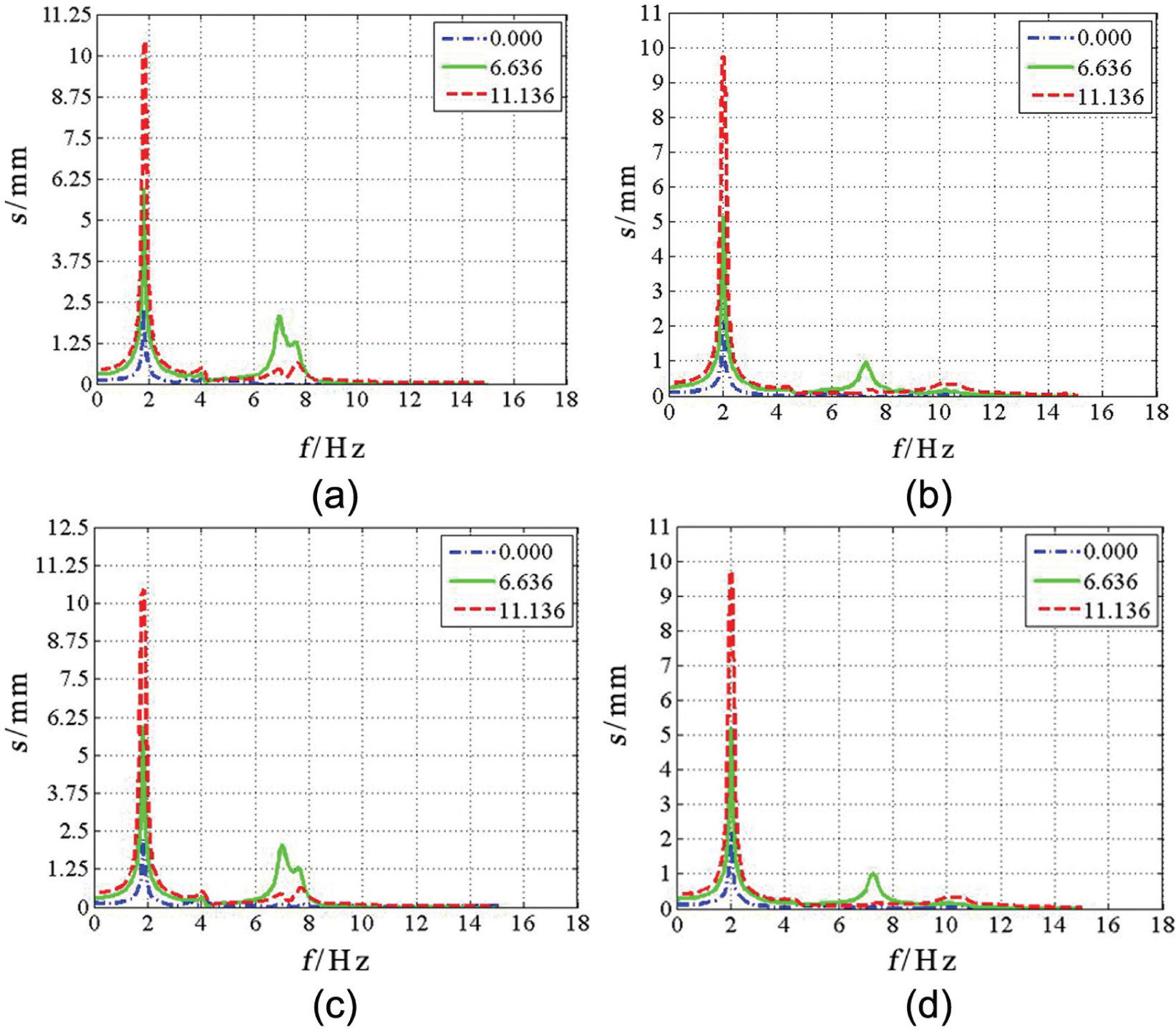
Typical displacement–frequency curves: (a) PT_01 X-direction, (b) PT_01 Y-direction, (c) PT_02 X-direction, and (d) PT_02 Y-direction.
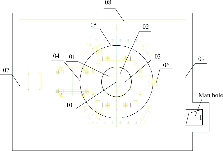
Points on the bedplate at ±0.000 elevation.
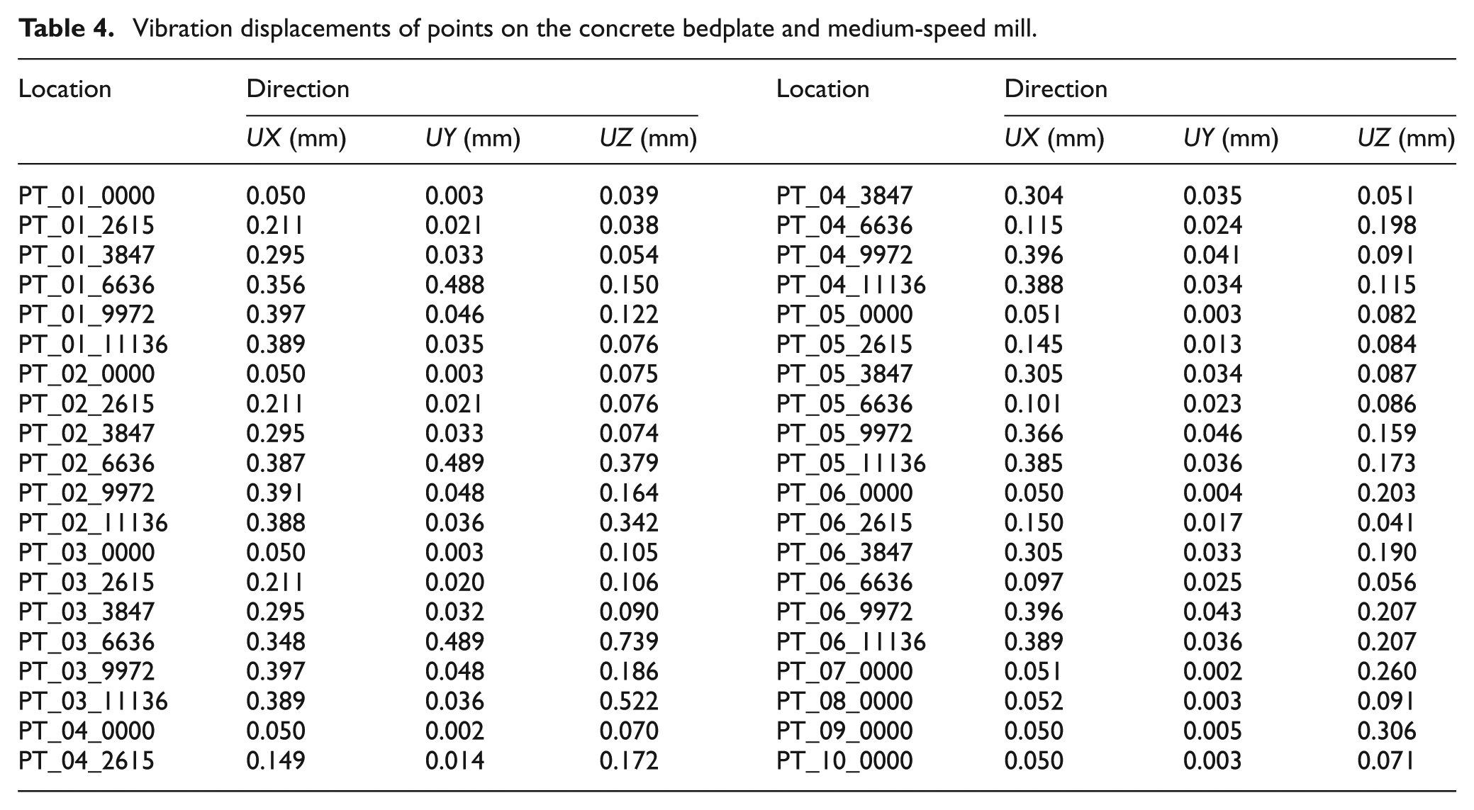
The vibration displacements at different elevations of the concrete bedplates and the medium-speed mill corresponding to the exciting frequency of 7 Hz can be obtained from the harmonic response curves; the associated results are shown in Table 4.
Vibration displacements of points on the concrete bedplate and medium-speed mill.
The comparison of the numerical and test results of the transverse horizontal vibration displacements is shown in Table 5. Test points 2, 3, and 4 are illustrated in Figure 2, and the numerical results of these points are associated with the test points in the finite element model. The numerical results generally agree with the test results, which verify the accuracy of the mill-foundation coupled model and the harmonic analysis.
Comparison of vibration displacements between the finite element analysis results and the field test results.

Parametric analysis of the vibration reduction of a medium-speed mill
To analyze the primary factors affecting the vibration of the medium-speed mill and its foundation, the number of isolators and the mass ratio of the foundation bedplate to the mill are considered in the harmonic response analysis. Assuming the number of isolators is equal to 16, 20, 24, 28, 32, and 36, and the mass ratio of the foundation bedplate to the mill is equal to 1.5, 2.0, 2.5, 3.0, 3.5, and 4.0, the calculation results derived from the harmonic response analysis are shown in Figure 8.
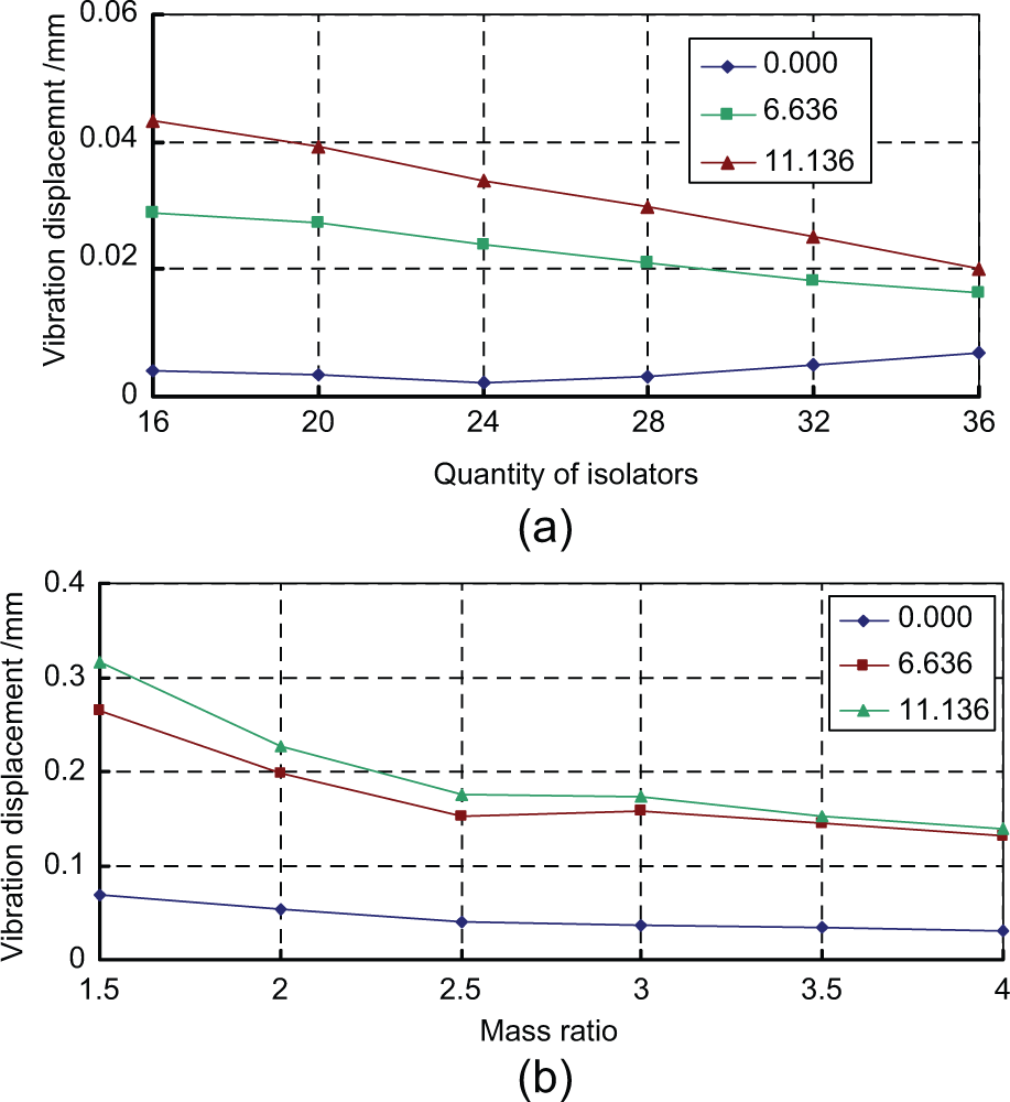
Influence of the quantity of isolators and the mass ratio on the vibration of mill: (a) PT_04_UY and (b) PT_01_UZ.
The analysis results show that as the number of vibration isolators increases, the natural vibration frequency of the model increases gradually, while the vibration response significantly decreases. When the number of vibration isolators is increased from 24 to 28, the vibration displacement is shown to decrease by 40% by means of statistics. The quantity of isolators can be determined by limiting the horizontal vibration displacement of the upper bedplate of the foundation in the design. The actual vibration displacement of the mill body is too large, according to the current limitation of 60 µm to the horizontal vibration displacement at the top surface of the foundation. Combined with the parametric analysis in this section, the limitation value of the vibration displacement at the top surface of foundation is suggested to be 50 µm.
With an increase in mass ratio, the natural vibration frequency of the model decreases gradually; the vibration response of the model can also be reduced by increasing the mass ratio. When the mass ratio increases from 2.5 to 3.0, the maximum vibration displacement at the top surface of the bedplate is shown to be reduced by 16%. Because the actual vibration displacement of the mill body is too large when considering the current limitation of the mass ratio (i.e. 2.5), and considering the parametric analysis in this section, the mass ratio of the foundation bedplate to the mill is suggested to be 3.0 ± 0.2.
Conclusion
In this article, the vibration behavior and vibration reduction measures of medium-speed mills in thermal power plants are investigated by field tests and finite element analyses. The major conclusions are summarized as follows:
The tested medium-speed mills with spring vibration–isolated foundations meet vibration safety requirements except for one mill in the Yuzhou power plant; this was evaluated according to the limitation value of vibration displacement at the top surface of the foundation as specified in some related codes. This shows that a spring vibration–isolated foundation can effectively reduce the vibration of a medium-speed mill. The horizontal vibration displacements of vibration-isolated foundations are shown to be nearly identical to those of non-isolated foundations, but the ground vibration displacements of non-isolated foundations are shown to be two to three times larger than the former.
In the design of medium-speed mills with spring vibration–isolated foundations, it is suggested that the vibration displacement of the mill body should be considered. It is also suggested that a model of the mill-foundation coupled system should be built to calculate and analyze its vibration characteristics. Although the vibration control index of the mill body is insufficient for the proper design of these systems, it can be used to reduce the vibration displacement of the mill body by controlling the vibration displacement of the foundation.
Finite element analysis results are shown to be basically consistent with the measured results, which verify that the finite element method is feasible to analyze the vibration performance of these types of mills. The dynamic characteristics and the vibration displacement under a disturbing force of the mill-foundation coupled system can be accurately estimated through modal and harmonic analyses. Thus, this method provides a basis for the dynamic optimization in the design of the foundation for medium-speed mills.
The results of the parametric analysis indicate that increasing the number of isolators can significantly reduce the vibration displacement at the top surface of the foundation, and increasing the mass ratio of the foundation to the mill can also decrease the vibration displacement at the top surface of the foundation effectively. It is thus proposed that the maximum horizontal vibration displacement of medium-speed mills with spring vibration–isolated foundations should be limited to 50 µm, and the mass ratio of the foundation to the mill should be limited to 3.0 ± 0.2.
Footnotes
Academic Editor: Anand Thite
Declaration of conflicting interests
The author(s) declared no potential conflicts of interest with respect to the research, authorship, and/or publication of this article.
Funding
This work was supported by the project of Shaanxi Province Excellent Young Scholars (2013KJXX-53), China Scholarship for Study Abroad, Program for Changjiang Scholars and Innovative Research Team in University, and Innovation Team of Xi’an University of Architecture and Technology.