
Abstract
The harsh weather conditions offshore wind turbine blades are working under have necessitated the need for a more effective approach for detecting their failures. Dynamic characteristics e.g., vibration, carry useful information related to blades structural health. Critical analysis of the blade’s free vibration represents one of the fundamental steps for assessing structural dynamics. When a rotating blade deflects, either in the plane of rotation or perpendicular to it, the centrifugal force exerts inertia force along the blade span, which increases the blade’s natural frequencies compared with the stationary ones. However, the influence of different blade parameters on the flap-wise vibrations is not very well understood. In this paper, the effects of such parameters on dynamic characteristics of National Renewable Energy Laboratory (NREL) 5-MW wind turbine blades are investigated using different beam theories. The examined models have been used to determine the natural frequencies and mode shapes of the National Renewable Energy Laboratory (NREL) 5-MW wind turbine. Results demonstrate that increasing angular velocity significantly impacts the natural frequencies and mode shapes. The rotary inertia is found to influence the free vibration responses of the studied blades. Moreover, increasing hub radius, pre-cone and pitch angles are found to have less influence on the natural frequencies. Mode shape comparisons were also carried out using MSF (modal scale factor) and MAC (modal assurance criteria). Compared to the other investigated methods, Bernoulli’s based algorithms are found to produce less accurate results.
Introduction
The blade is considered one of the most critical components in a wind turbine due to the unpredictable external forces such as the atmospheric environment and varying operational conditions. The challenge is further complicated as the size of the blade becomes larger and as the wind turbines are constructed in more difficult terrains.1,2 Blades are a major contributor to the downtime of wind turbines and account for over 41% of total failures. 3 Therefore, vibration analysis has been and continues to be a subject of immense importance because it leads to understanding the dynamic characteristics of wind turbine blades. Natural frequencies and mode shapes play an essential role in the design and control of these structures. The blade is usually modelled as a rotating beam. The out-of-plane bending vibration of the Euler-Bernoulli beam is examined in, 4 which uses the variational iteration technique. Natural frequencies and mode shapes of a rotating beam are studied for various angular velocities and different taper ratios. The flexural free vibration analysis of a double tapered Euler-Bernoulli is investigated in. 5 The differential transform method technique is used to solve the governing differential equation. The centrifugal force is incorporated in order to find its effect on the dynamic characteristics. A composite Timoshenko beam (TB) with single delamination travelled by a constant amplitude moving force is modelled in. 6 The governing differential equation of motion is derived, and the effects of shear deformation and rotary inertia have been accounted for. Eigen-values technique and Ritz method were used to obtain the dynamic response under the action of moving force. The mechanical behaviour of the delamination layers is modelled by a piecewise-linear spring foundation. 6 The flap-wise bending vibration of a rotating tapered Rayleigh beam is analysed in. 7 The integral equation method was developed to determine the natural frequencies. The influences of hub radius, rotational speed, taper ratio and rotary inertia on the natural frequencies are elucidated. The horizontal axis wind turbine blades were developed with varying cross-section that gradually twists from circular at the root to different aerofoil profile along the blade span. These types of blades are usually installed on the hub with a pre-cone angle and a pitch angle during the operation process. The contributions of pre-cone angle and the pre-twist angle variation on the kinetic and strain energy, the influences of centrifugal force and rotary inertia are addressed in. 8 Hamilton’s principle in combination with differential transform method is used, 9 the free vibration analysis of a Timoshenko beam featuring in the direction of the transverse bending-lateral bending-torsion coupling is analysed based on energy expressions. Thus, the kinetic and the potential energy are used to incorporate the rotary inertia, shear deformation, rotational speed, hub radius and bending-bending-torsion coupling deformation. The work in 10 reports the development of a vibration monitoring system to estimate the deflection at the tip of the blade, especially in cases when the blades begin to vibrate excessively. Analytical methods are used in 11 to investigate the forced vibration of the symmetric cracked Timoshenko beam under harmonic excitations. The response displacement and the rotating angles of a coupled bending and torsional vibrations of the cantilever Timoshenko beam are studied. Analytical methods are used in 11 to investigate the forced vibration of the symmetric cracked Timoshenko beam under harmonic excitations. The response displacement and the rotating angles of a coupled bending and torsional vibrations of a cantilever Timoshenko beam are studied. The TB is divided into several segments due to the existence of cracks. 11 The general form of Green’s functions of each beam segment with the unknown boundary conditions is derived. The study described the matching conditions of the cracked cross-section and the relationship between the boundaries of the beam segments. The damaged cross-section is modelled as a mixture line-spring, and the compliances are determined through the Paris equation. The study found that the depth, location and number of cracks have significant effects on the natural frequencies of the TB. Also, the location of cracks can be easily positioned by the discontinuity of the beam response. If the wind turbine blade has a long span, it is appropriate to simplify the blade as a non-uniform beam. In each blade section, the shear centre may not be coincident with the beam centroid, which leads to a coupled bending and torsional vibration. There have been several studies examining the influences of coupled vibrations on the dynamic response. The differential transform method is applied in 11 to solve the coupled partial differential equations. 12 A non-linear beam model based on the geometrically exact beam theory is used in 13 to build the wind turbine blade. Taking the NREL 5MW wind turbine blade as an example, the free vibration analysis is used to investigate the dynamic analysis under periodic unsteady inflows.
As stated, due to the externally applied force from a precise atmospheric environment and varying operational conditions, the free vibration analysis of the wind turbine blade is the first issue that should be addressed accurately to find the modal parameters. Numerous studies with different approaches have been carried out to investigate the flap-wise vibration of rotating beams. Some studies have adopted Euler-Bernoulli rotating-beam theory4,5 or even non-rotating Bernoulli beam due to its simplicity. Timoshenko beam theory which added the rotary inertia and shear deformation was also considered for vibration analysis.6,7 Rayleigh beam theory14,15 is among the main methods used as it investigates free vibration by considering the rotary inertia, which is found to have an influence on the dynamic characteristics and forced response of wind turbine blades. The work in 8 uses Rayleigh beam theory and incorporates the influence of the pitch and pre-cone angles on the dynamic characteristics of the horizontal axis wind turbine blade in the flap wise direction. The study in 13 is adopted the geometrically exact beam theory to find the natural frequencies and corresponding mode shapes in the flap-wise and edge-wise directions to find the deflection response in both directions. Despite the significant contribution being made to analyse the flap-wise vibration, there are some shortcomings. The aforementioned studies4,5,6,7 did not achieve accurate free vibration results that would predict the dynamic response of the blade. However, unless a comprehensive dynamic model takes into account parameters such as centrifugal forces, rotary inertia, gravity, angular velocity, hub radius, pre-cone and pitch angles, the supplying input data to model-based control would be inaccurate. A significant advance was made in 8 by scrutinising the effects of harmonic excitation due to the gravitational force, pre-cone and pitch angles, in addition to the other parameters. However, a shortcoming in the study was not applying the comparison of methods on a blade with the same geometry. Furthermore, despite mentioning the significant effects of pitch and pre-cone angles with increasing the rotating speed, the results did not clarify these effects or the mentioned factors' effect on the high natural frequencies. The work in 13 is found the natural frequencies of a single blade at zero rotation speed. However, the natural frequencies without considering the influences of centrifugal force and different values of rotation speed would not be accurate and sufficient as a comprehensive model.
In this study, the comparison between different beam theories is established for the model of modern wind turbine blades. The finite element code is written using the specification of 5MW NREL blade for structural modelling and simulation studies. Modal properties, including the natural frequencies, translational mode shapes, angular mode shapes, modal scale factor and modal shape correlation coefficient, are compared. The effect of changing the blade parameters, including hub radius, pitch and pre-cone angles, on the blade performance is investigated. The effect of increasing the angular velocity on the modal parameters is also studied.
Derivation of the governing equations
In this study, the horizontal axis wind turbine blade under the flap-wise vibration is considered. The effect of rotary inertia, centrifugal force, and the effect of pre-cone and pitch angles are included. The blade deformation can be expressed by the superposition of static displacement-time independent- and dynamic displacement due to the influence of angular velocity and axial component of gravity force. The blade is modelled by a cantilever beam with variable cross-sections. One end of the blade is fixed to a rigid hub with radius R, and the other is free. The blade is considered to rotate at an angular velocity
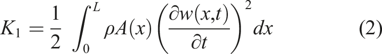
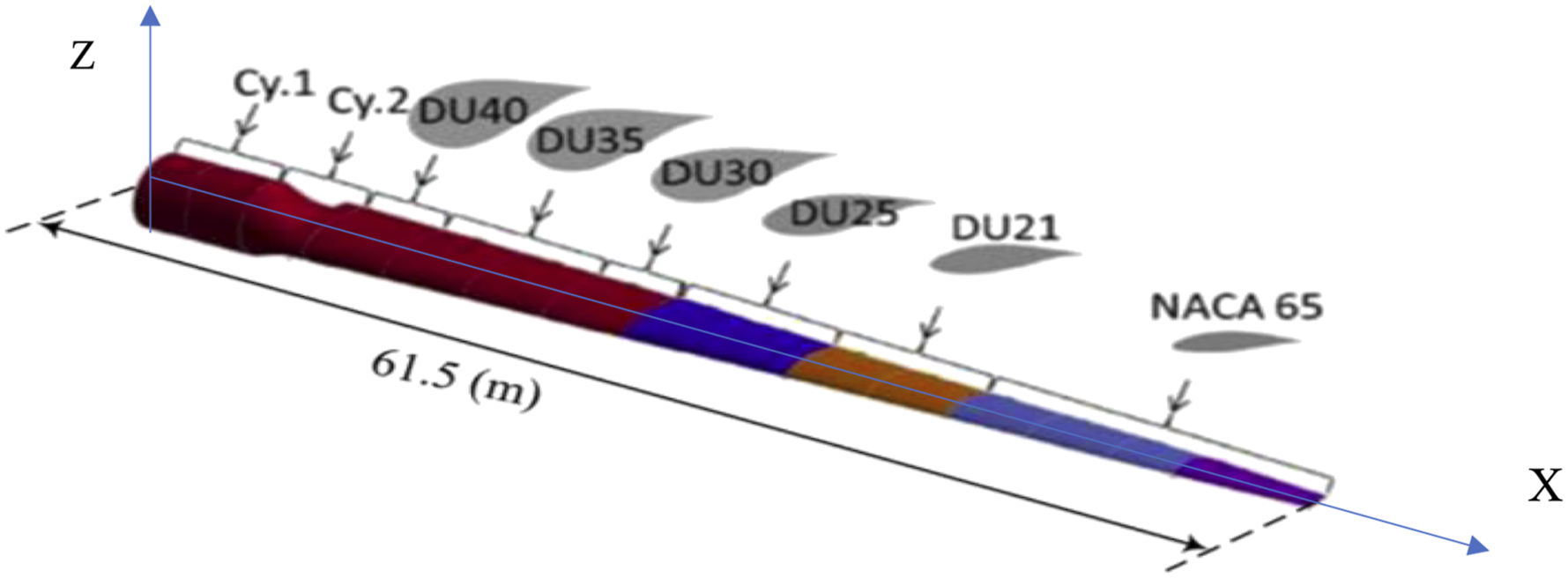
The blade being considered in this study is shown in Figure 2. The Z-axis is along the hub’s central axis; the X-axis is along the spanwise of the blade, and Y-axis follows the right-hand rule. The total kinetic energy of the horizontal axis wind turbine blade due to the flap-wise vibration is

The first term is due to the flap-wise bending, expressed as
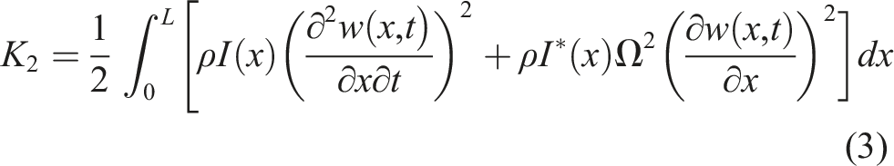
The second expression of the kinetic energy results from the rotary inertia of the blade, as follow
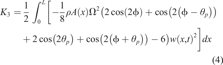
The last term of the kinetic energy is resulted from adding the effects of pre-cone and pitch angles, and comes from the fact that the axis of rotation is not parallel with the flap-wise direction of the blade.
8
In the above equations:
The first term of the kinetic energy equation (1) is due to the flexural vibration of the flap-wise direction and is identical to the Bernoulli, Timoshenko and Rayleigh beam theories. The second and third terms are due to the rotary inertia of the blade. These terms are ignored in the Euler-Bernoulli theory. The second term is found in the Timoshenko beam theory. The third term comes from the fact that the axis of rotation is not parallel with the flap-wise span by the effect of pre-cone and twist angle of the blade. 8
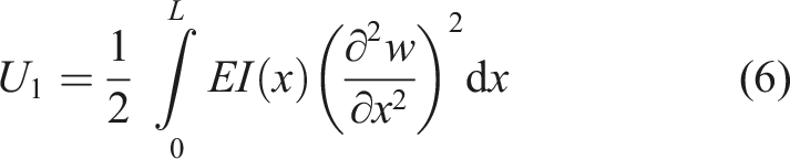
The potential energy of the HAWT blade is

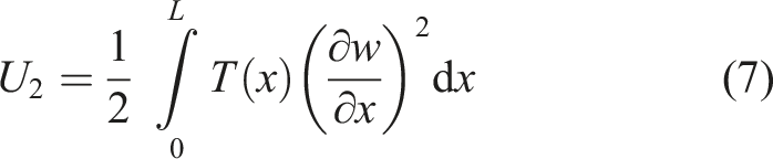
The strain energy of the blade due to flap-wise bending is
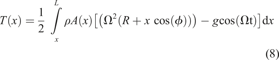
The potential energy due to the centrifugal force is
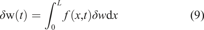
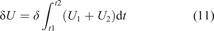
The virtual work of the applied distributed force,
Noting that the operation of variation is commutative with respect to both integration and differentiation. So, the variation of kinetic and potential energy can be written as
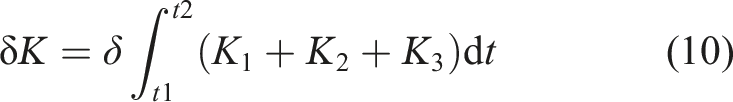
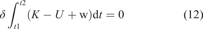
Hamiton’s principle can be stated as

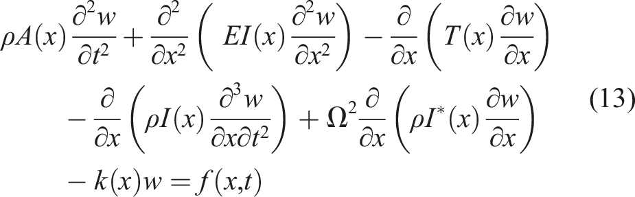
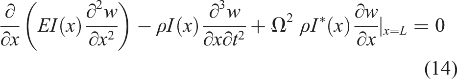
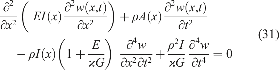
The governing equation of motion is obtainable as
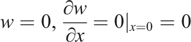
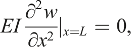
and at x=L
Free vibration analysis
There are many methods that may be used to find the free vibration analysis of rotating beams. Most of those methods are applied for beams with certain cross-sections. Therefore, they cannot be applied to the blade with various and complicated cross-sections. Approximate methods such as Galerkin residual approach can be adopted. The governing equation (13) together with approximate solution
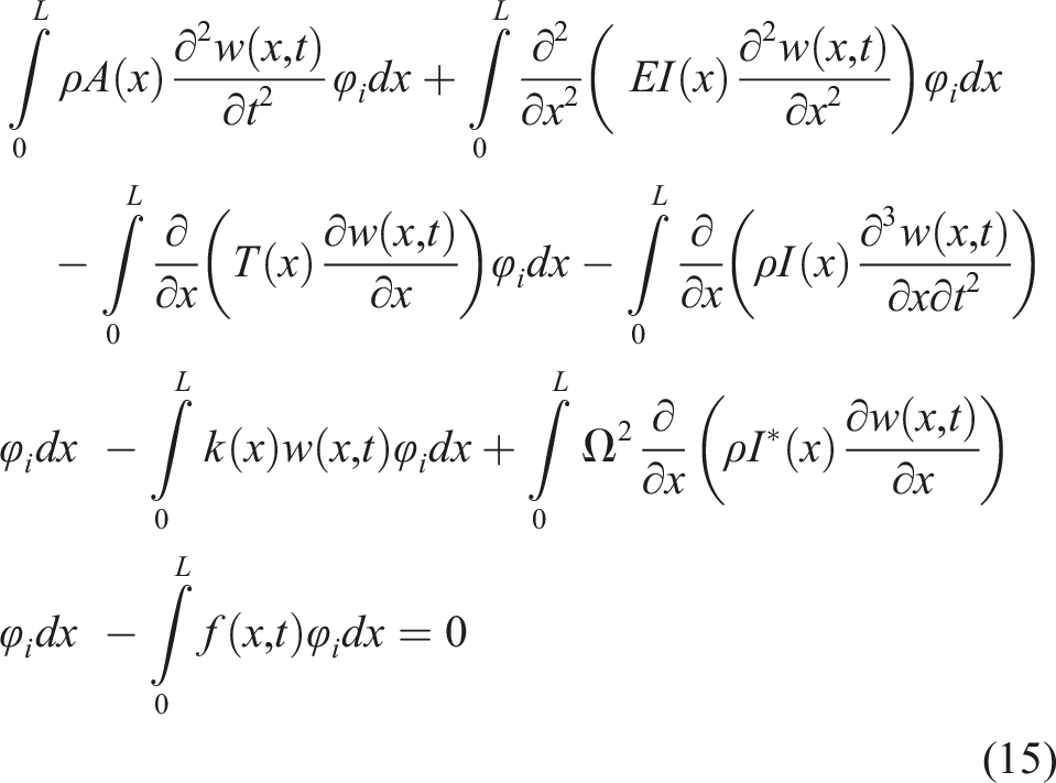
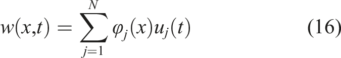
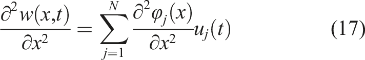
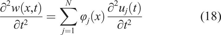
The flap-wise deflection and the slop due to flexural vibration of the wind turbine blade are approximated by a weighted linear combination of trial functions
16
The second derivatives of the trial solution are expressed as


From equations (20), we get

If the damping matrix
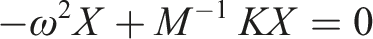

The previous equations yield the

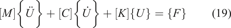
The governing equation of the flap-wise deformation equation (15) is transformed to the general form of the matrix equations for free vibration of N degree of freedom system as indicated in equation (23) which it is represented the fundamental equation to form the pertinent equations to determine the natural frequencies and mode shapes configuration of the wind turbine blades. The elements of mass and stiffness matrices are
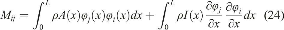
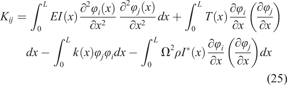
The global mass and stiffness matrices can be constructed once the elementary value of mass and stiffness from equations (24) and (25) were obtained.
Figure 1 shows the computational procedure that followed in order to programming the free vibration analysis. Free vibration computational procedure.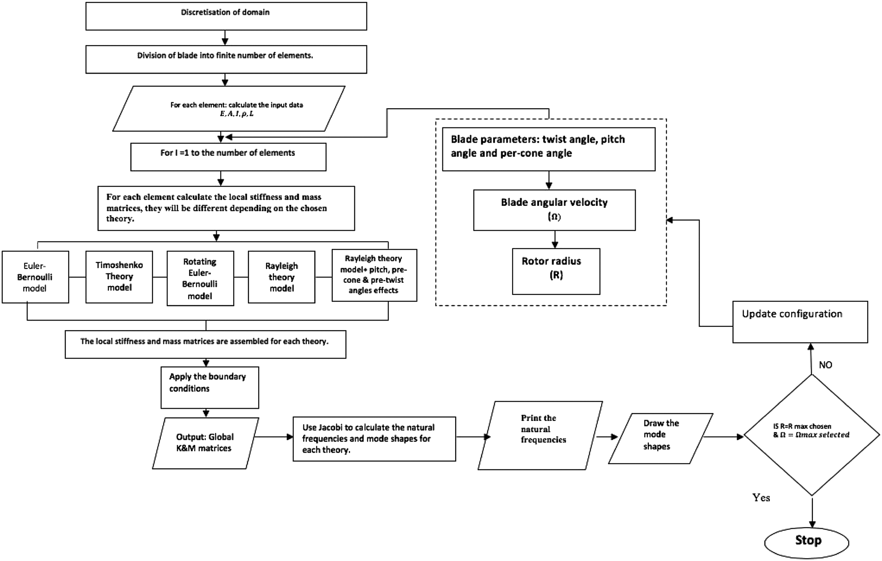
Applicability of Euler-Bernoulli, Rayleigh and Timoshenko beam theories in fap-wise deformation
If the first two terms of equation (13) are considered, and the rest parts are neglected, the Euler-Bernoulli beam’s governing equation for the forced flap-wise vibration of non-uniform and non-rotating beam is obtained as
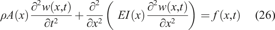
If the third term of equation (13) is added, the Euler-Bernoulli rotating beam’s governing equation for the forced flap-wise vibration of non-uniform beam is obtained as
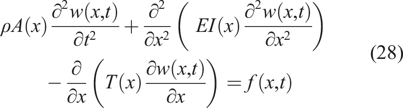
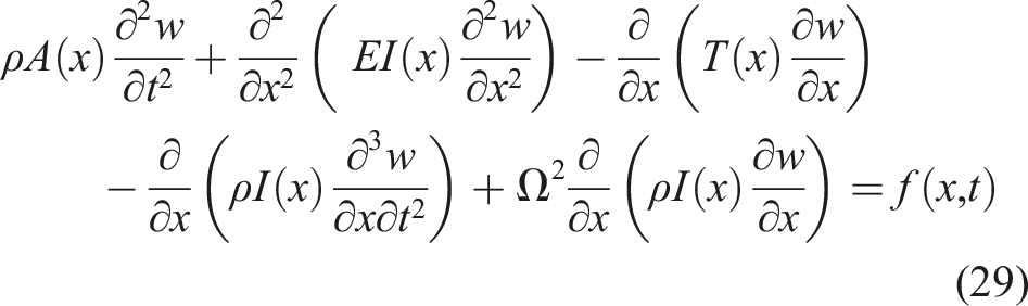
The governing equation for a rotating Rayleigh beam can be expressed directly from equation (13) by neglecting the terms of the effect of pre-cone and pitch angles to be as
If the shear deformation and rotary inertia are considered, the procedure, presented by Timoshenko beam theory. The governing equation for the forced flap-wise vibration of non-uniform beam is obtained as
16
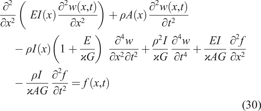
For free vibration equation (29) reduces to
Shear correction value of wind turbine blade
Timoshenko beam theory is based on the concept of a characteristics response to shear force. The theory adopts the correction shear factor that compensates for the assumption of a constant shear strain over the cross-section. The shear factor is a reciprocal value that primarily depends on the shape of structure cross-section, on the other hand, Timoshenko suggested constant value of shear coefficient depending on the shape of cross-section; for the symmetric beam with a rectangular section, it is 0.83, whilst with a circular cross-section it is 0.9. 17 This correction value is defined as the average shear strain within a section to the shear strain at its centroid. 18 The study 19 adopted many methods to evaluate the shear correction values. All the values are estimated according to the aspect ratio of the cross-section; the value of the circular cross-section is 0.9 and this value decreases with decreasing the ratio of aspect ratio to 0.286. 19
The primary design drivers for large wind turbine blades are blade fatigue, as wind blades are required to be certified for 20 years of life span. Moreover, the natural modes of vibration, which are determined by its physical behaviour are inherent to the dynamic system, need to be predicted with accurate values. The forces on the blade element are assumed to calculate by means of the dimensional of each aerofoil characteristic along the spanwise direction of the blade.
20
Based on the technical report,
21
the blade is divided into 17 different elements considering the coincident aerofoil in each element,
22
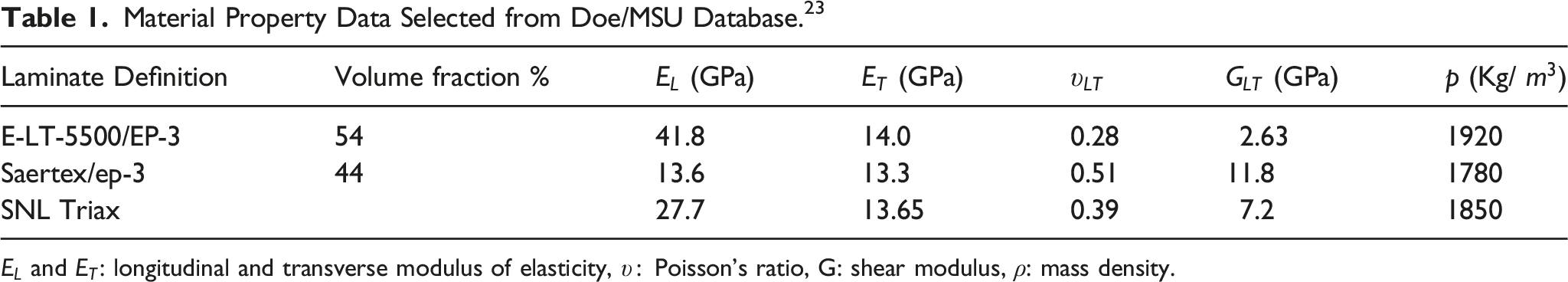
as shown in Figure 2. According to the Composite Material Fatigue Database,
23
the elastic material property data and mass density are listed in Table 1. Properties for triaxial material, which are denoted as SNL Triax, were determined by averaging the test-derived data for the uni-axial and double bias material.
23
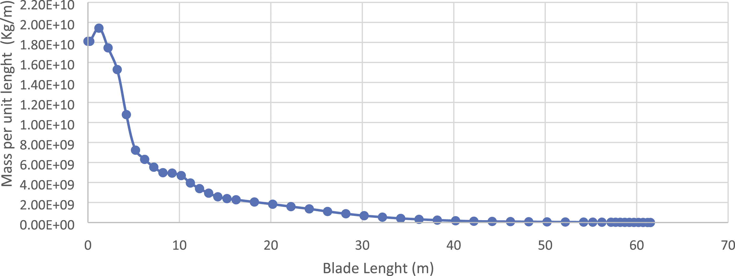
Splines were drawn for mass and stiffness along the blade span according to data,
21
as shown in Figure 3 and Figure 4 are clarified the complicated distribution of blade mass and stiffness along the blade span. In this study, the correction shear factor starting at the value of 0.9 as the first section is circle cross-section and decreasing according to the chord and thickness of different blade aerofoils.
21
Division of the blade into 17 elements.
21
Material Property Data Selected from Doe/MSU Database.
23
the mass per unit length (ρA) distribution along the spanwise of NREL 5MW blade.
21
the flap-wise flexural rigidity (EI) distribution along the spanwise of NREL 5MW.
21

Comparison and correlation between mode shapes
It is possible to identify the structure condition from the variation of modal-based indices such as the frequency and mode shapes. The aim is to obtain the baseline of structure modal parameters when it is perfectly healthy. However, when any changes of these parameters occur, it may be possible to derive the causes which bring about the change.
The mode shapes are spatially distributed characteristics that include information about the structure. The first index for quantifying the comparison between the pairs of mode shapes is Modal Scale Factor(MSF). This technique represents the slope of the individual points of mode shapes which these points should be close to the straight line through which they will have a slope of 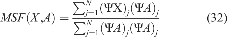
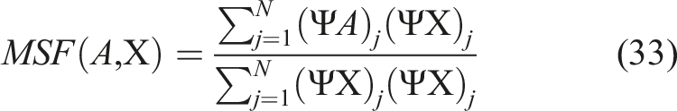
If
In the second case, they differ by a simple scalar multiplier
The second index is the Modal Shape Correlation Coefficient (MSCC) and this provides the correlation of two pairs of the mode shapes.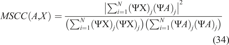
The
Results and discussion
The flowchart of the algorithm that used in this study is shown in Figure 1. The National Renewable Energy Laboratory (NREL) 5MW reference wind turbine is chosen to validate the previous equations and analysis. It is an upwind three-blade horizontal-axis multi-megawatt wind turbine. Based on the technical report
21
the blade is divided into 17 different elements considering the coincident aerofoil in each element, as shown in Figure 2. The rotor radius and the hub diameter of the blade are about 63m and 3m, respectively. The pre-cone and pitch angles are
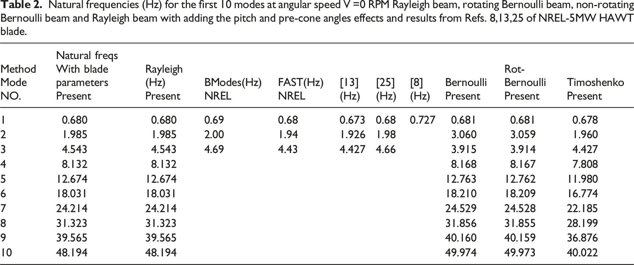
The data in Table 2 shows the first 10 natural frequencies of the NREL 5MW at zero rotational speed. The comparison is made between the natural frequencies by applying the different beam theories: Rayleigh, rotating Bernoulli, non-rotating Bernoulli beams, and with the blade parameters such as pitch, pre-cone angles and gravitational force component, for the same geometry and material properties of NREL-5MW HAWT blade. The comparison is made against the BModes and FAST codes, and from,8,13,25 it was found that the results obtained by the present study agree well with the numerical results calculated from other investigations. The fundamental frequencies by adopted different theories in this study have approximately the same value, which indicates that ignoring the influence of centrifugal force at the stationary value, lead to the same results in the fundamental mode. In the same Table 2, there is a significant change in the second and third frequencies for both rotating and non-rotating Bernoulli theory. According to equations (26) and (28) the rotary inertia effect is not included, and, as a result, it has a significant impact on the second and third modes. However, this impact becomes less in the higher modes.
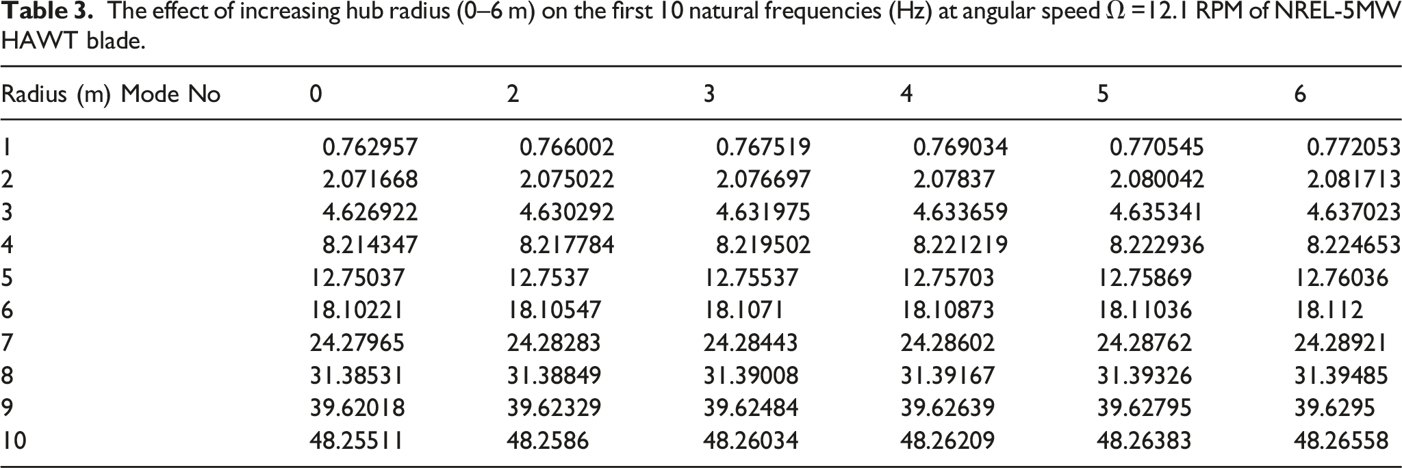
The effect of increasing hub radius (0–6 m) on the first 10 natural frequencies (Hz) at angular speed Ω =12.1 RPM of NREL-5MW HAWT blade.
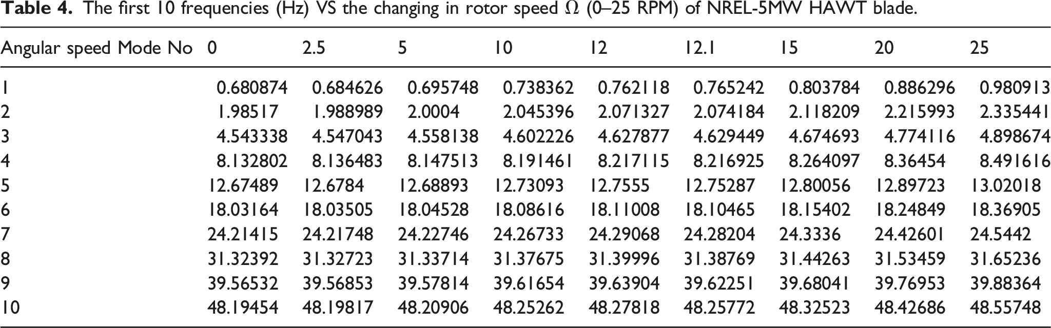
The first 10 frequencies (Hz) VS the changing in rotor speed Ω (0–25 RPM) of NREL-5MW HAWT blade.
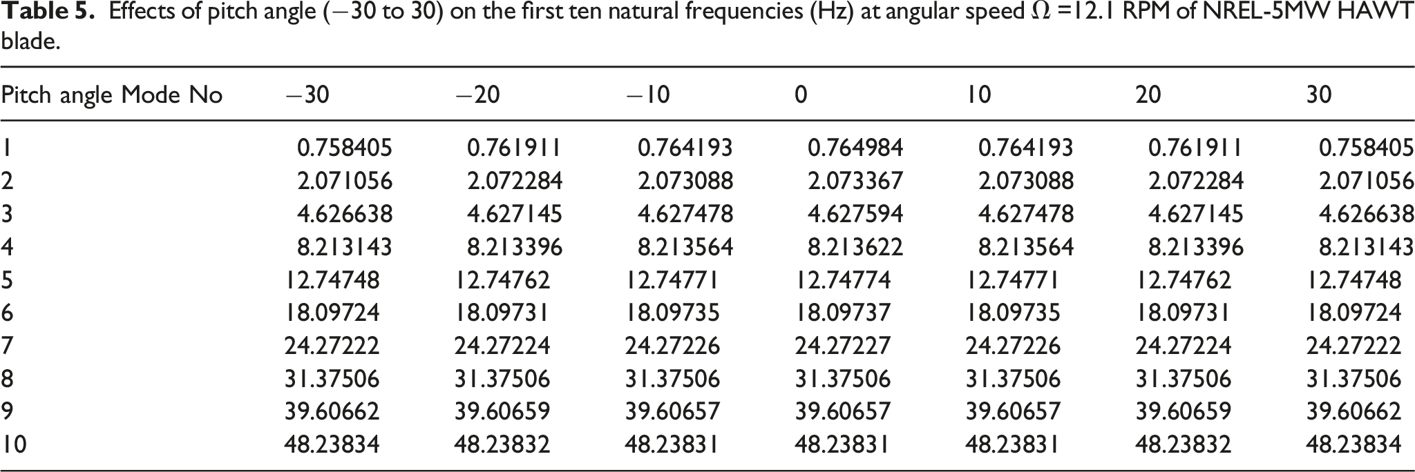
Effects of pitch angle (−30 to 30) on the first ten natural frequencies (Hz) at angular speed Ω =12.1 RPM of NREL-5MW HAWT blade.
Effects of pre-cone angle (−5 to 5) on the first 10 natural frequencies (Hz) at angular speed Ω =0 RPM of NREL-5MW HAWT blade.
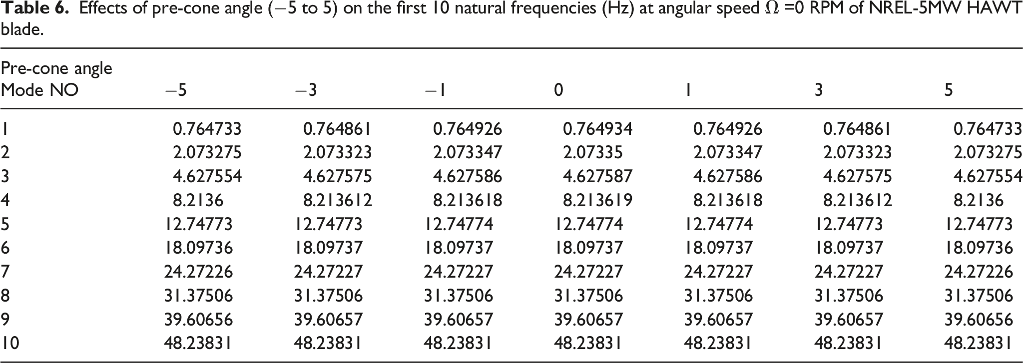
Figure 5 shows the first six mode shapes for Rayleigh, rotating Bernoulli, non-rotating Bernoulli and Timoshenko beams, and blade parameters such as pitch, pre-cone angles, and gravitational force component at angular velocity = 0 RPM. The mode shapes from different theories are superimposed on the same figure to show the shape comparison. The figures show that the fundamental mode has the same path line in all adopted theories. The discrepancy was clearly noticed in the second and third modes. However, this agrees with the discrepancy in natural frequencies in the same modes and confirms that the rotary inertia significantly impacts the second and third modes. As in Table 2 and Figure 5, it can be seen from mode number four that the effect of rotary inertia is significantly decreasing, and its influence on the dynamic characteristics become less important in all modes higher than mode four. In Figure 5 it is possible to see that not only the degree of corresponding between the pairs of mode shapes is achieved, but also the nature of any discrepancies which do exist. It can be pointed out that the blade parameters such as pitch and precone angles have not affected the mode shapes. Furthermore, the rotating and non-rotating- Bernoulli methods have also the same mode shapes, which indicate that the existence of rotary inertia with their counterparts theories has an impact on the mode shapes. This elucidates that the influence of adding centrifugal force has no effect at a stationary value of angular velocity, whilst the rotary inertia has an impact on the first three of natural frequencies and mode shapes. Mode shapes of the first six modes of NREL-5MW HAWT blade at rotational speed=0 RPM.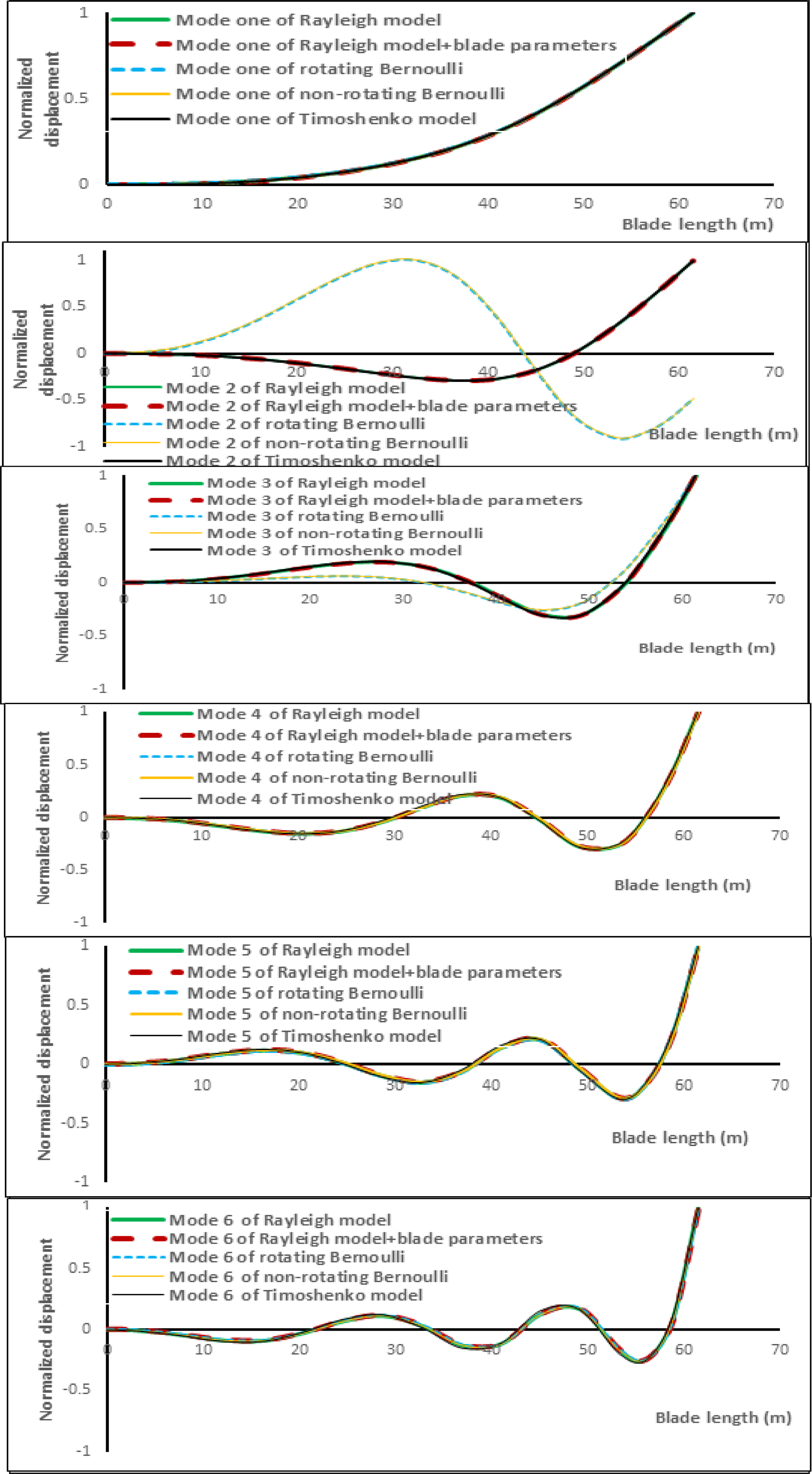
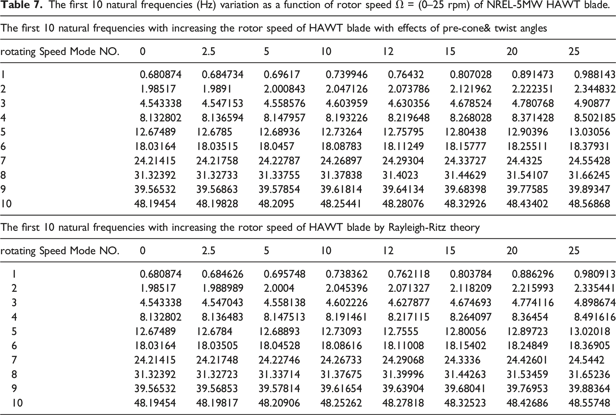
The first 10 natural frequencies (Hz) variation as a function of rotor speed Ω = (0–25 rpm) of NREL-5MW HAWT blade.
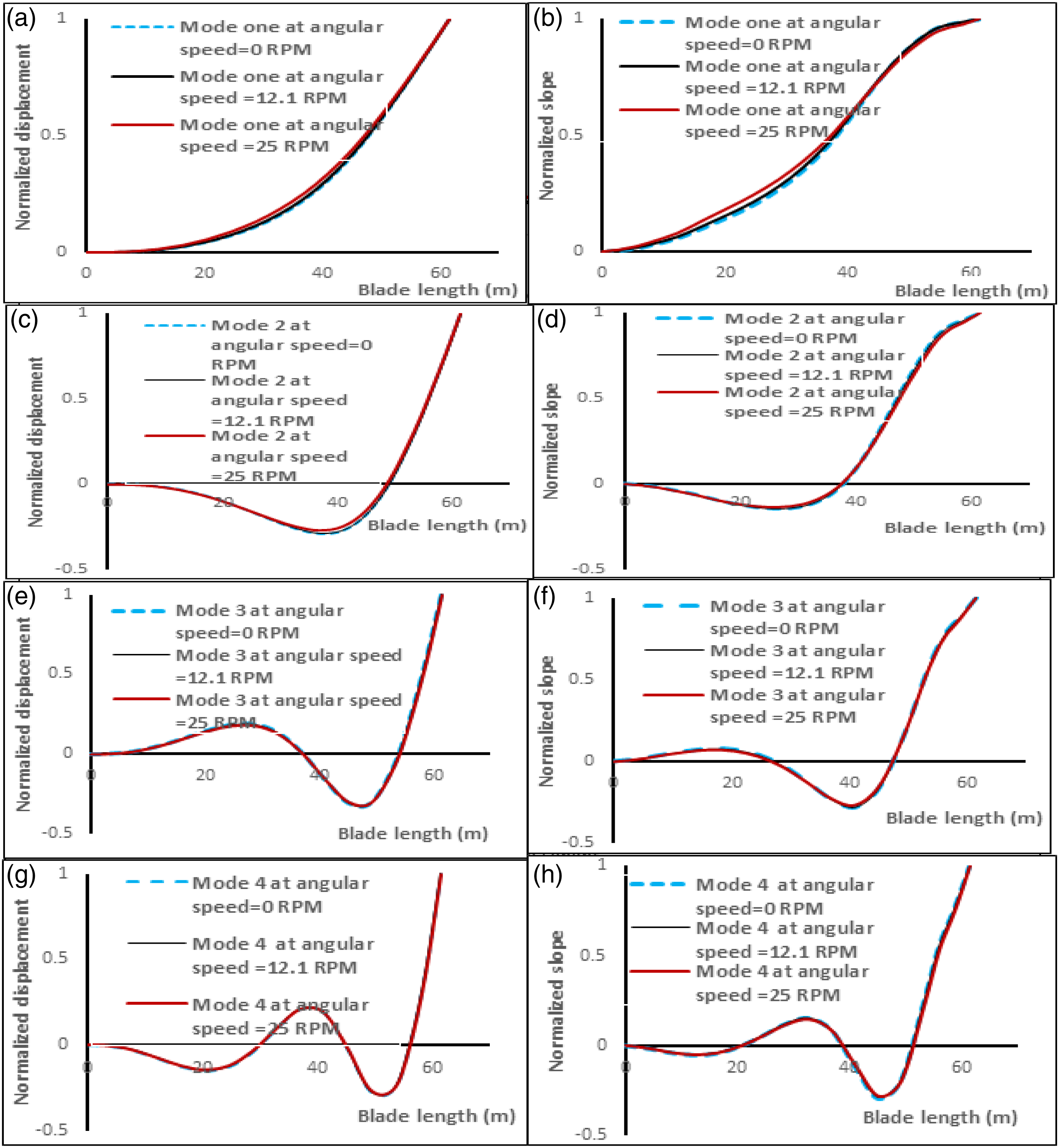
The first, second, third and fourth mode shapes of NREL-5MW HAWT blade at different angular velocities.
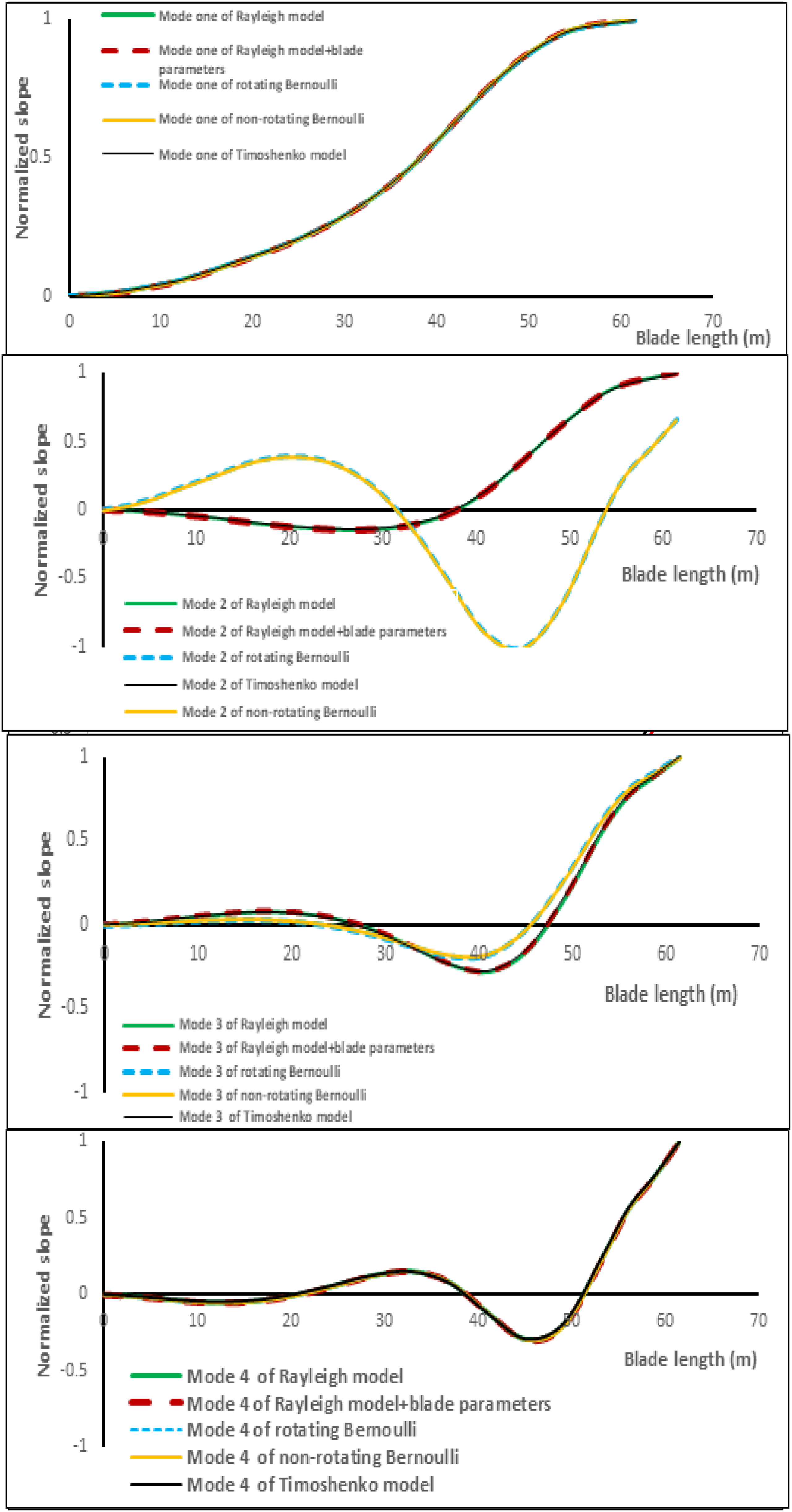
The first, second, third and fourth angular mode shapes of NREL-5MW HAWT blade at rotational speed=0 RPM
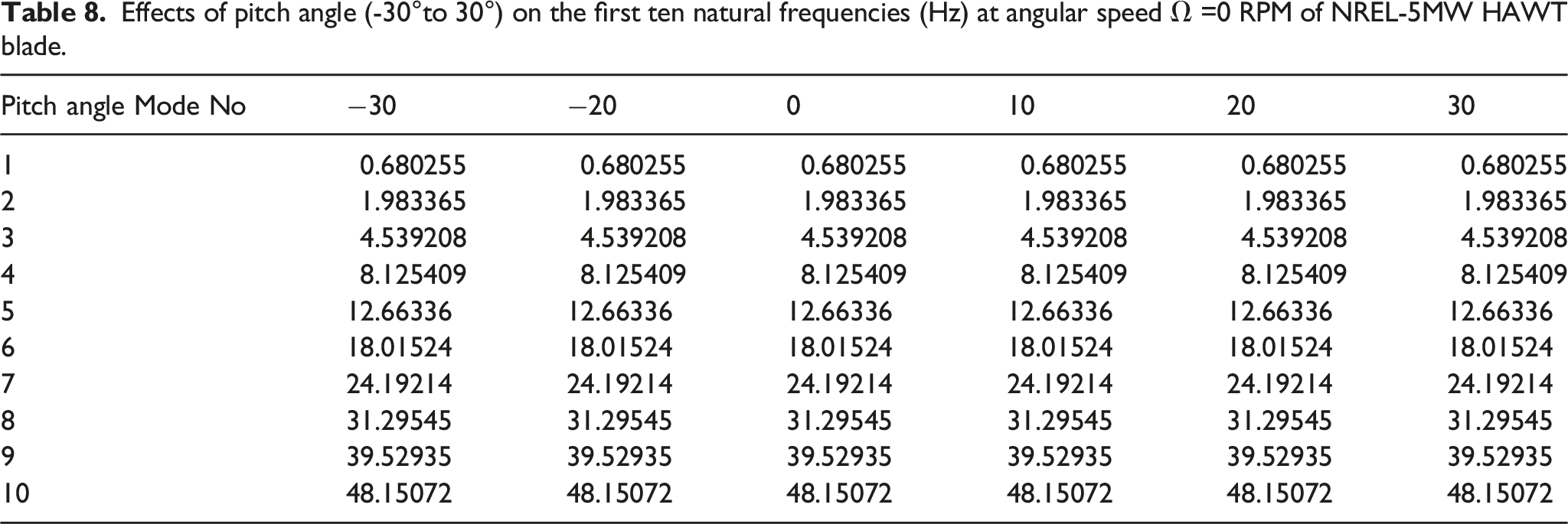
Effects of pitch angle (-30°to 30°) on the first ten natural frequencies (Hz) at angular speed Ω =0 RPM of NREL-5MW HAWT blade.
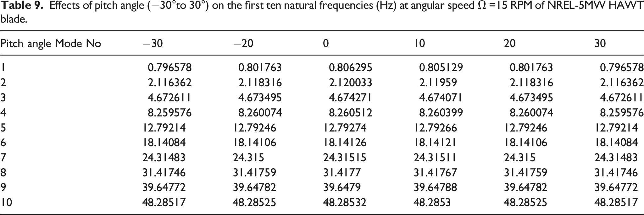
Effects of pitch angle (−30°to 30°) on the first ten natural frequencies (Hz) at angular speed Ω =15 RPM of NREL-5MW HAWT blade.
Effects of pitch angle (-30°to 30°) on the first ten natural frequencies (Hz) at anngular speed Ω =25 RPM of NREL-5MW HAWT blade.
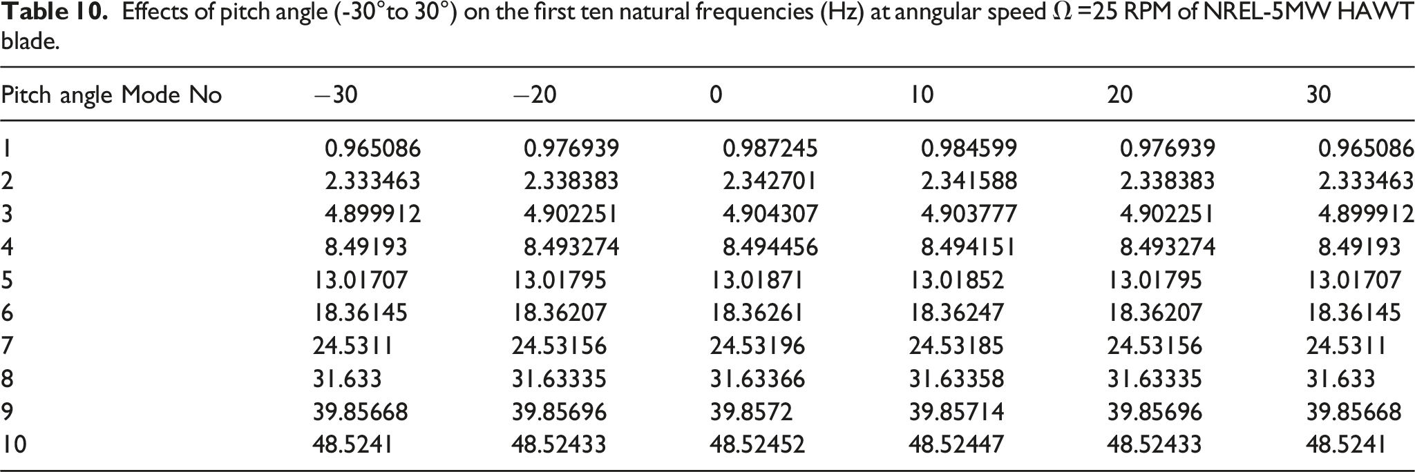
Table 9 shows the influence of changing the pitch angle at angular velocity = 15 RPM. The frequency values are increasing by increasing the rotational speed. Furthermore, these frequency values are slightly changing with changing the pitch angle, and this change becomes less and less in the higher modes. According to Table 10, the natural frequencies become higher by around 30% at angular speed = 25 RPM comparing to Table 8. As in Table 9, the changes in frequencies with changing the pitch angle are barely noticeable in the lower and higher modes at rotational speed =25 RPM.
Figure 8 shows the comparisons between the first 10 frequencies values for all the adopted theories against the frequencies of the Rayleigh theory for each of the modes included in the comparison. From the figure, it can be seen the degree of correlation between the counterparts of the results. Furthermore, it can be noticed that the Rayleigh model without the effect of control angles is closely correlated with the Rayleigh model with the effect of blade control angles. Furthermore, there is a high level of correlation in the Timoshenko model compared with the Rayleigh model. first 10 natural frequencies of the 5 MW wind turbine blade by different theories.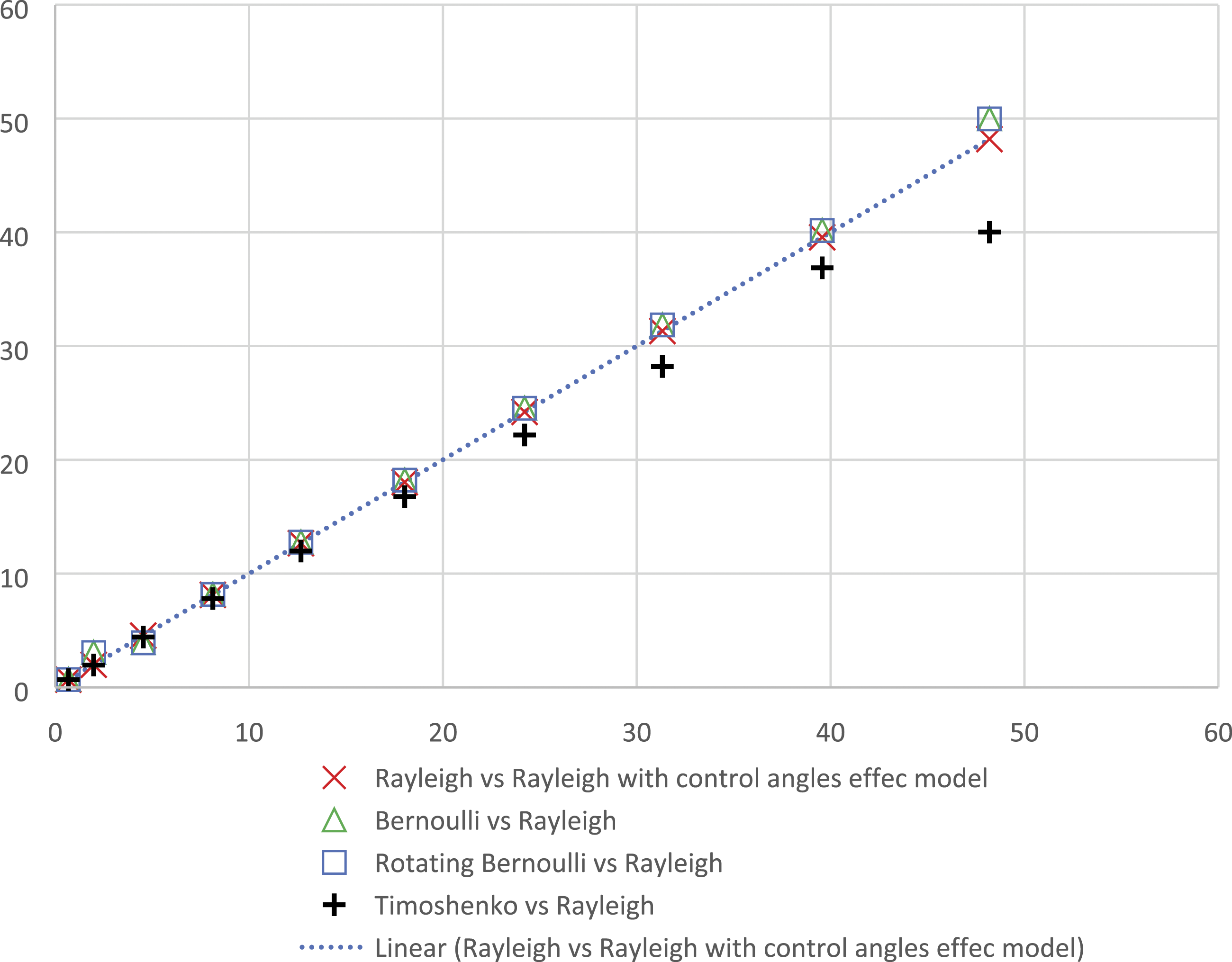
Whilst Figure 9 shows the natural frequencies at different rotation speeds versus counterparts frequencies at rotational speed = 0 rpm. As illustrated, the frequencies are coincident with the stationary values along the line 45°, which indicates no apparent discrepancies between them. However, some positive identification of each mode with its counterpart can be achieved clearly by the mode shape correlation method. frequencies of various rotational speed vs. the stationary values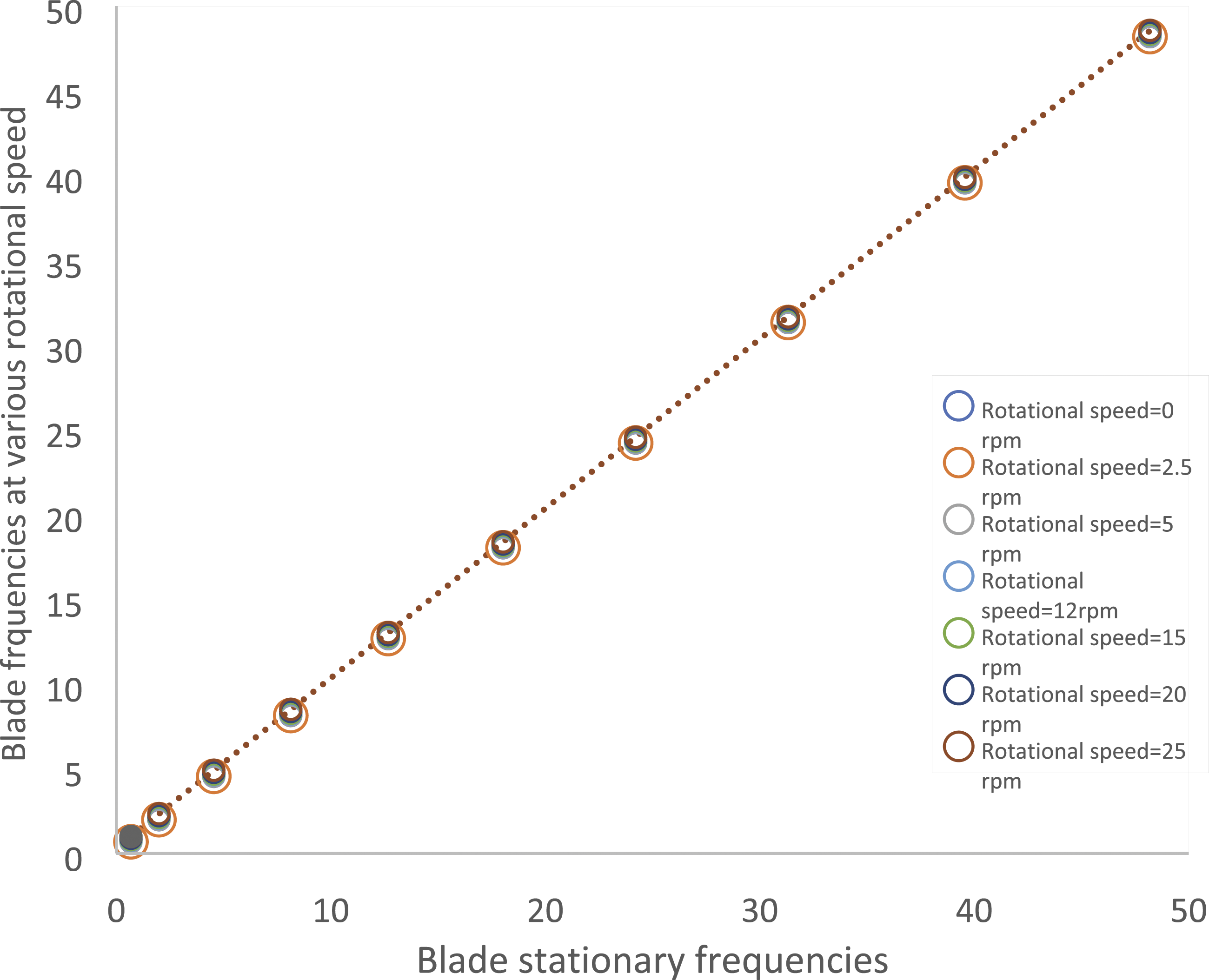
The results of MSF are demonstrated in Figure 10 for the first three mode shapes in the case of rotational velocity = 012.1 and 15 RPM. Although the three modes in different pairs of modes are correlated and close to one for counterparts values, the figure shows the scalar multiplier γ becomes less when comparing the modes at 12.1 RPM rotating speed with 15 RPM. It reveals that this parameter gives small sensitivity of MSF index as it represents the slope of the best straight line through the pairs of comparing mode shapes points. The deviation of first three mode shapes by applying Modal Scale Factor index, blade at rotating speed=12.1 RPM, blade at rotating speed =0 RPM comparing with rotational speed =15 RPM.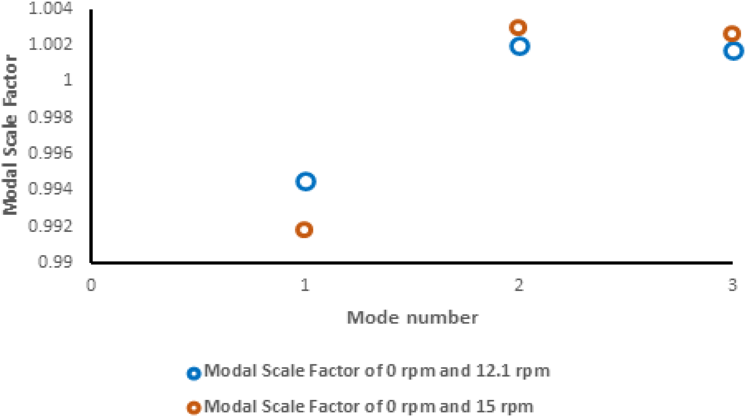
Figure 11 shows the Mode Shape Correlation Coefficient index results of the pairs of the first three mode shapes for quantifying the comparison between them at different rotational speeds. The MSCC results are not significantly deviated which all values are close to unity. The MSCC values of mode shapes at 0 RPM counterpart of mode shapes at 15 RPM exhibit more deviation comparing with values of mode shapes at 12.1 rpm counterpart of mode shapes at 15 RPM. However, MSCC results are very close to the unity, and any small sensitivity may bring a change in the structural characteristics. The deviation of first three mode shapes by applying Mode Shape Correlation Coefficient index, blade at rotating speed=12.1 RPM, blade at rotating speed =0 RPM comparing with rotational speed =15 RPM.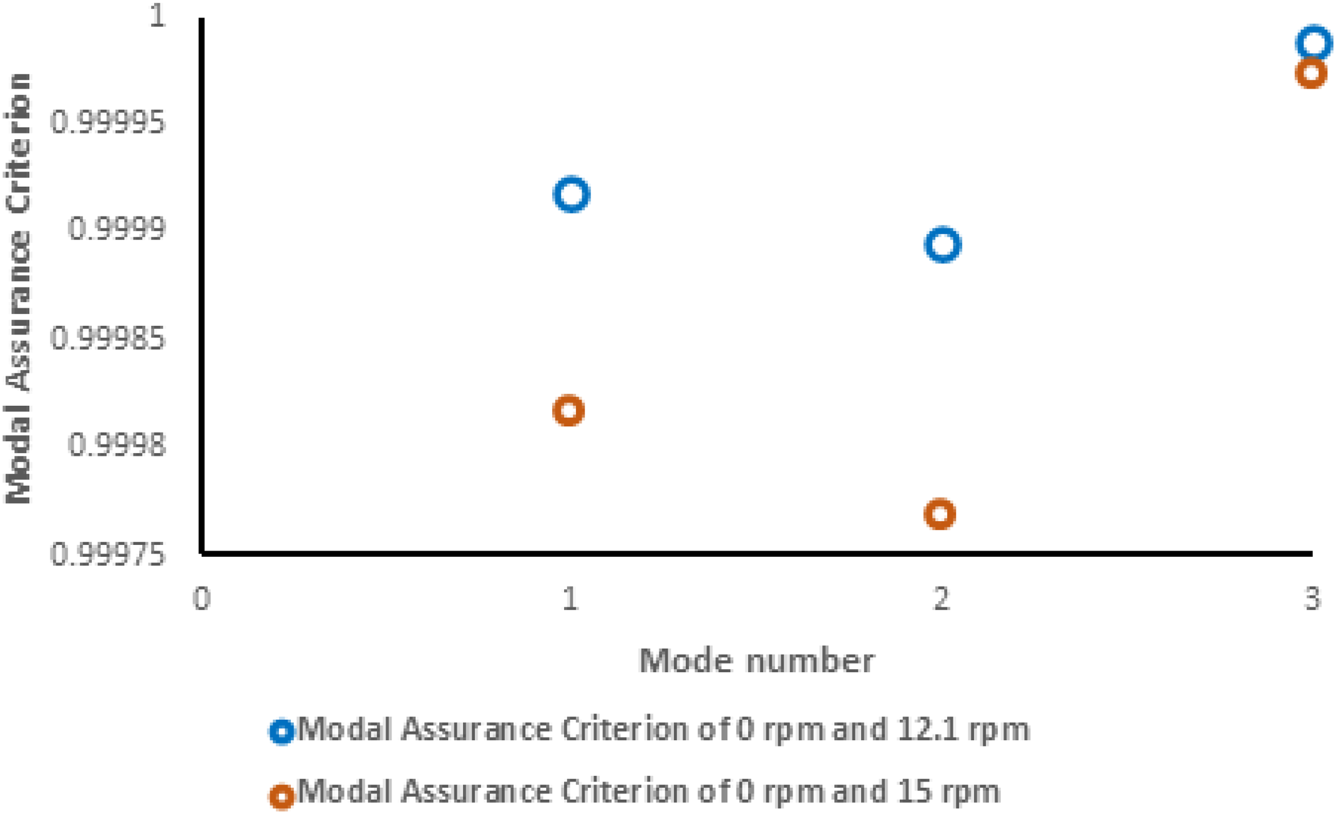
An alternative approach to comparing the mode shapes is by making an x-y plot to represent each element in the mode shape vector, such as is shown in Figure 12. The first six mode shapes of the Rayleigh model with and without the effect of pitch and pre-cone angles are represented in this figure. Each individual type of point on this figure is related to a specific degree of freedom. It could be noted that all the points in all the first six modes lie close to a straight line passing through the origin, which indicates the two models are perfectly correlated. The comparison of 5 MW blade mode shapes, Rayleigh model with control angles effect vs Rayleigh model without control angles effect.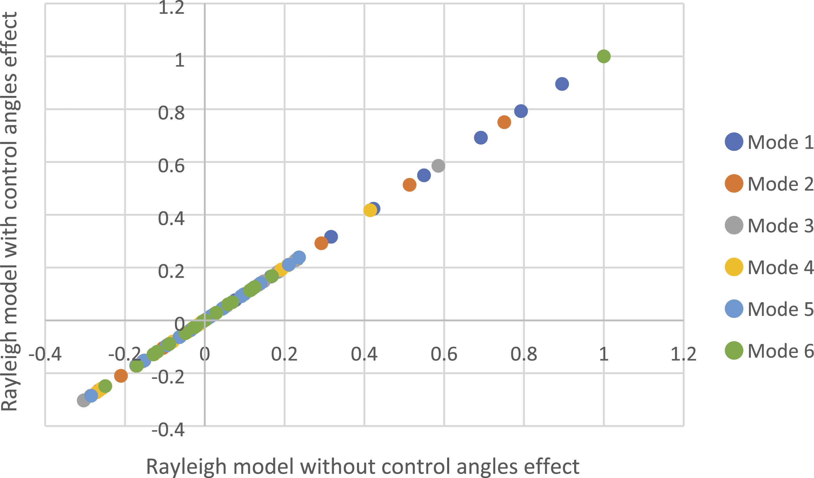
The data is represented in Figure 13 to compare the first six mode shapes of the Rayleigh and Timoshenko models in the case of the translational mode shapes Figure 13 a and angular mode shapes Figure 13 b. It is clear that there are discrepancies from the straight line in angular mode shapes. The deviations of the points from the expected line are systematic in some way in the second, three and fourth modes which indicates the existence of a correlation between them. There is a deviation in mode one, which infers that the effect of shear deformation may affect the angular mode shape due to the existence of shear angle. The discrepancy is increased in mode six in the same figure, which indicates the effect of shear in the higher modes. . a. The comparison of 5 MW blade of translational mode shapes, Rayleigh model vs Timoshenko model b. The comparison of 5 MW blade of angular mode shapes, Rayleigh model vs Timoshenko model.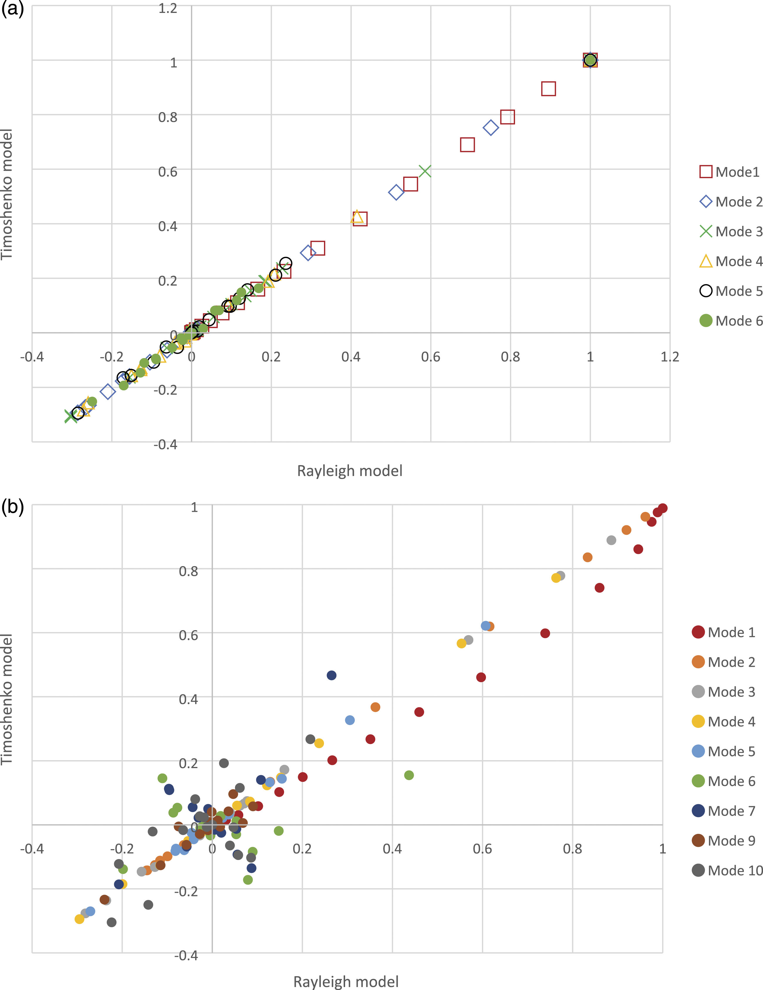
Figure 14 and Figure 15 represent the MAC for the translational and angular mode shapes data of the Rayleigh model comparing with adding the blade parameters such as pre-cone and pitch angle effect. The figures show that the data from the two models are perfectly correlated in the case of translational mode shapes Figure 14, and angular mode shapes Figure 15. From Figures 14 and 15, it could be noticed that only the first six modes are included. The MAC matrix is symmetric, and there are non-zero off-diagonal numbers that indicate that some of the mode shapes appear to exhibit a degree of correlation with each other, which may not be expected since the orthogonality between non-diagonal modes is predictable. However, the orthogonality property can only be translated to a perfect condition when all the degrees of freedom are included in the comparison. MAC index of translational mode shapes of 5 MW blade, correlation of Rayleigh and Blade with adding the control angles models. MAC index of angular mode shapes of 5 MW blade, correlation of Rayleigh and Blade with adding the pitch and pre-cone angles effect.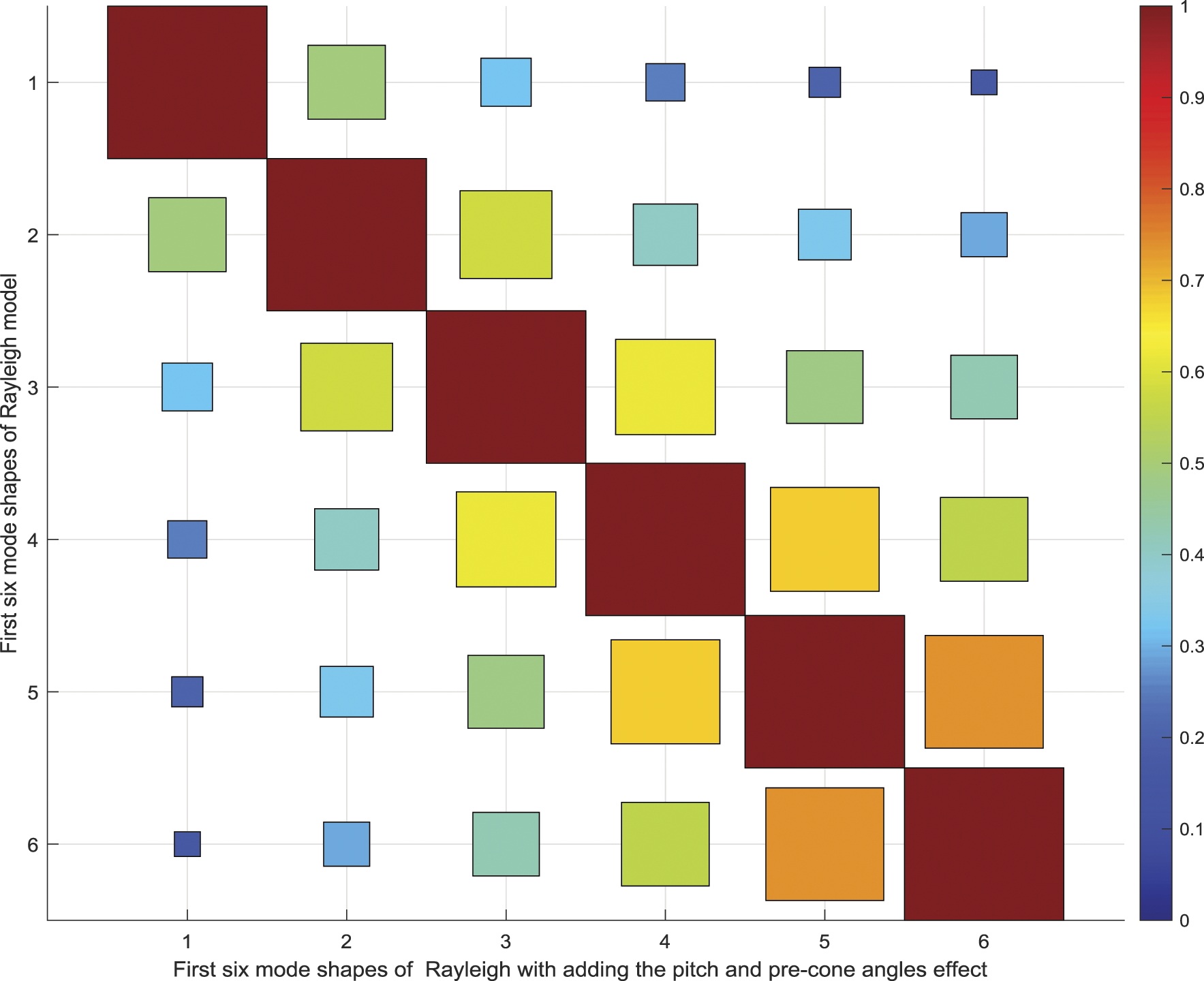
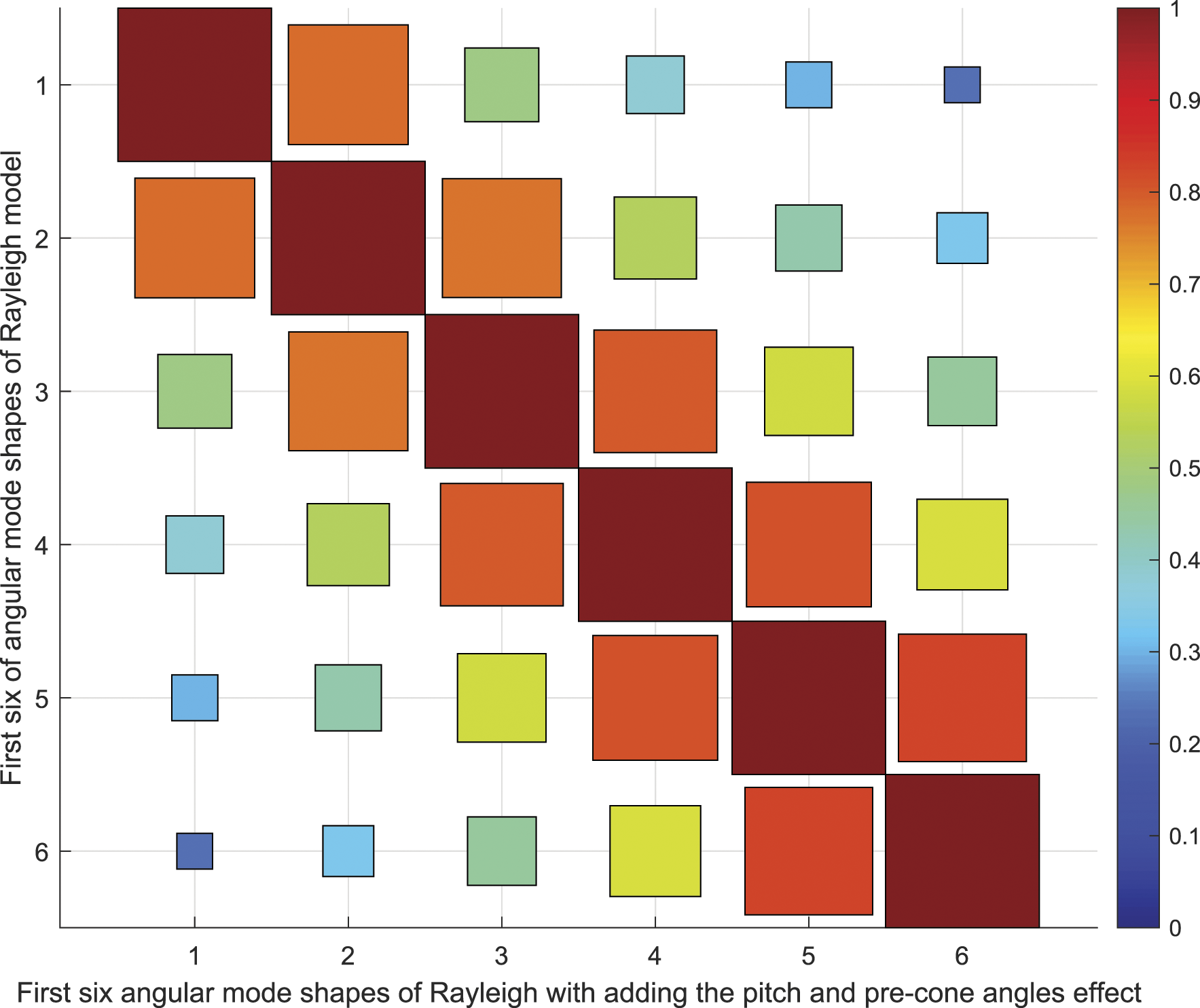
Figure 16 and Figure 17 represent the MAC matrices of the Rayleigh model with rotating speed = 0 RPM and 25 RPM in the case of translational and angular mode shapes. The correlation was slightly different in both figures. There are discrepancies in the matrix values around the diagonal comparing with the MAC matrix of the Rayleigh model in the case of translational and angular mode, as shown in Figures 16(b) and 17(b). It could be interpreted as the modes appear to exhibit a different degree of correlation between each other. a. MAC index of translational mode shapes of 5 MW blade, correlation of Rayleigh models at 0 RPM and 25 RPM.b, correlation of Rayleigh model with and without the blade control angles effect at 0 RPM. a. MAC index of angular mode shapes of 5 MW blade, correlation of Rayleigh models at 0 RPM and 25 RPM. b, correlation of Rayleigh model with and without the blade control angles effect at 0 RPM.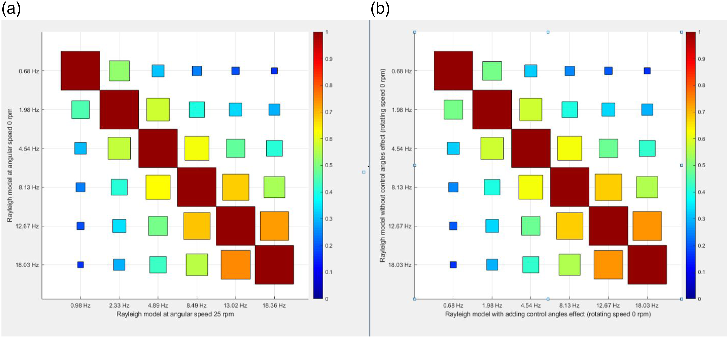
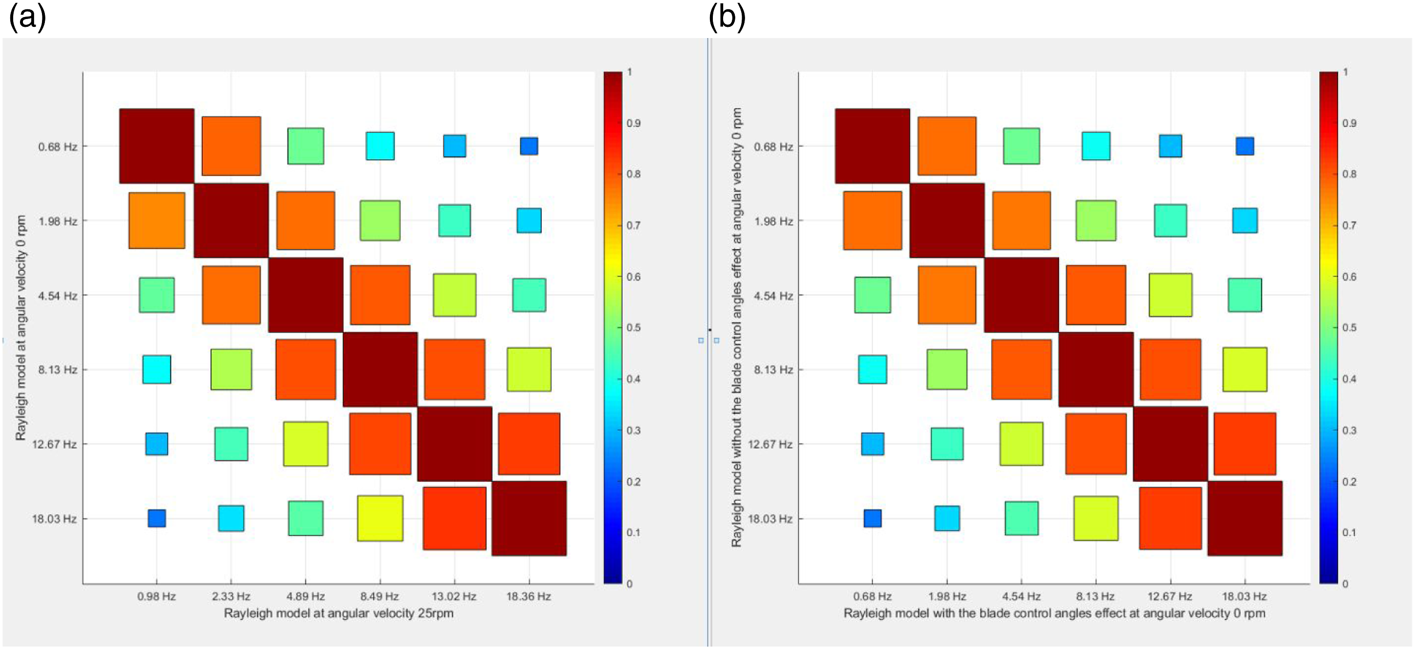
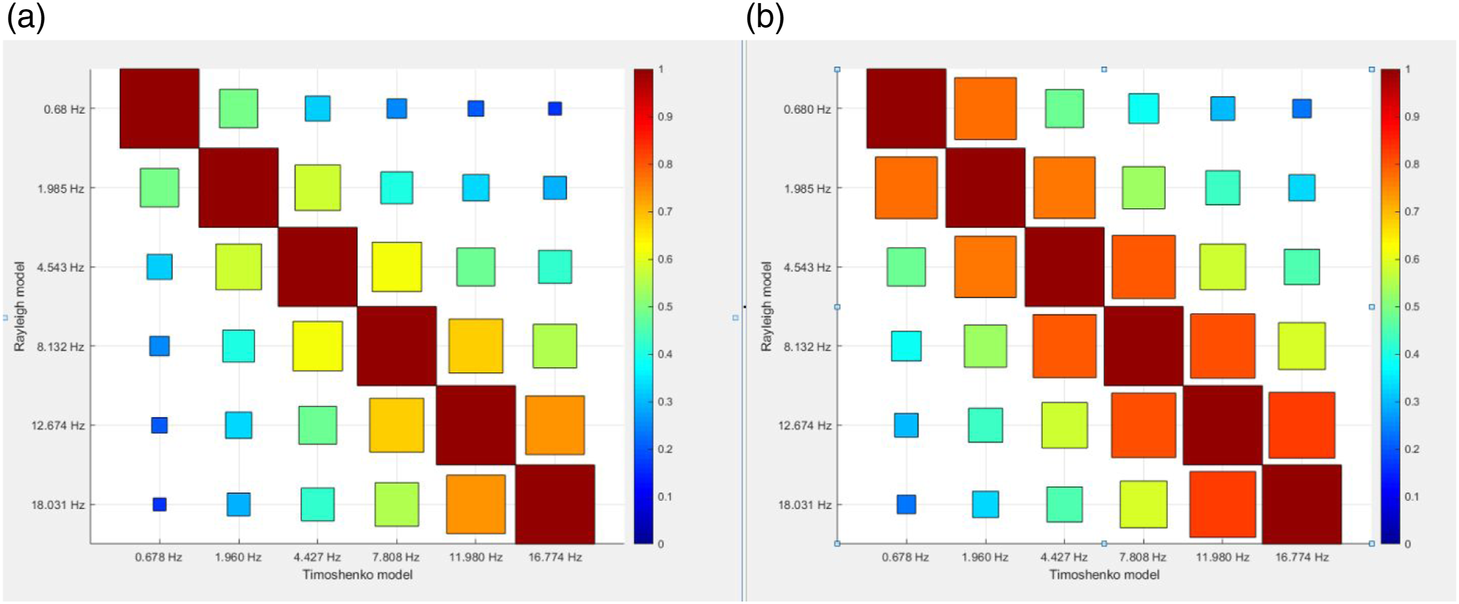
Figure 18 represents the MAC index of the rotating Bernoulli model comparing with the Rayleigh model at rotating speed = 0 RPM. In Figure 18 a, the matrix represents the translational mode shapes whilst 18 b represent the angular mode shapes. Both of them exhibit poor correlation in modes two and three. The MAC index of Timoshenko theory comparing with Rayleigh theory is showed in Figure 19 a and b in case of translational and angular mode shapes. The figures show a perfect correlation between the two models. a. MAC index of translational mode shapes of 5 MW blade, correlation of Rayleigh model and rotating Bernoulli model at 0 RPM.b, correlation of angular mode shapes of Rayleigh model and rotating Bernoulli model at 0 RPM. MAC index of 5 MW blade. a, correlation of translational mode shapes of Timoshenko and Rayleigh models; b, correlation of angular mode shapes of Timoshenko and Rayleigh models.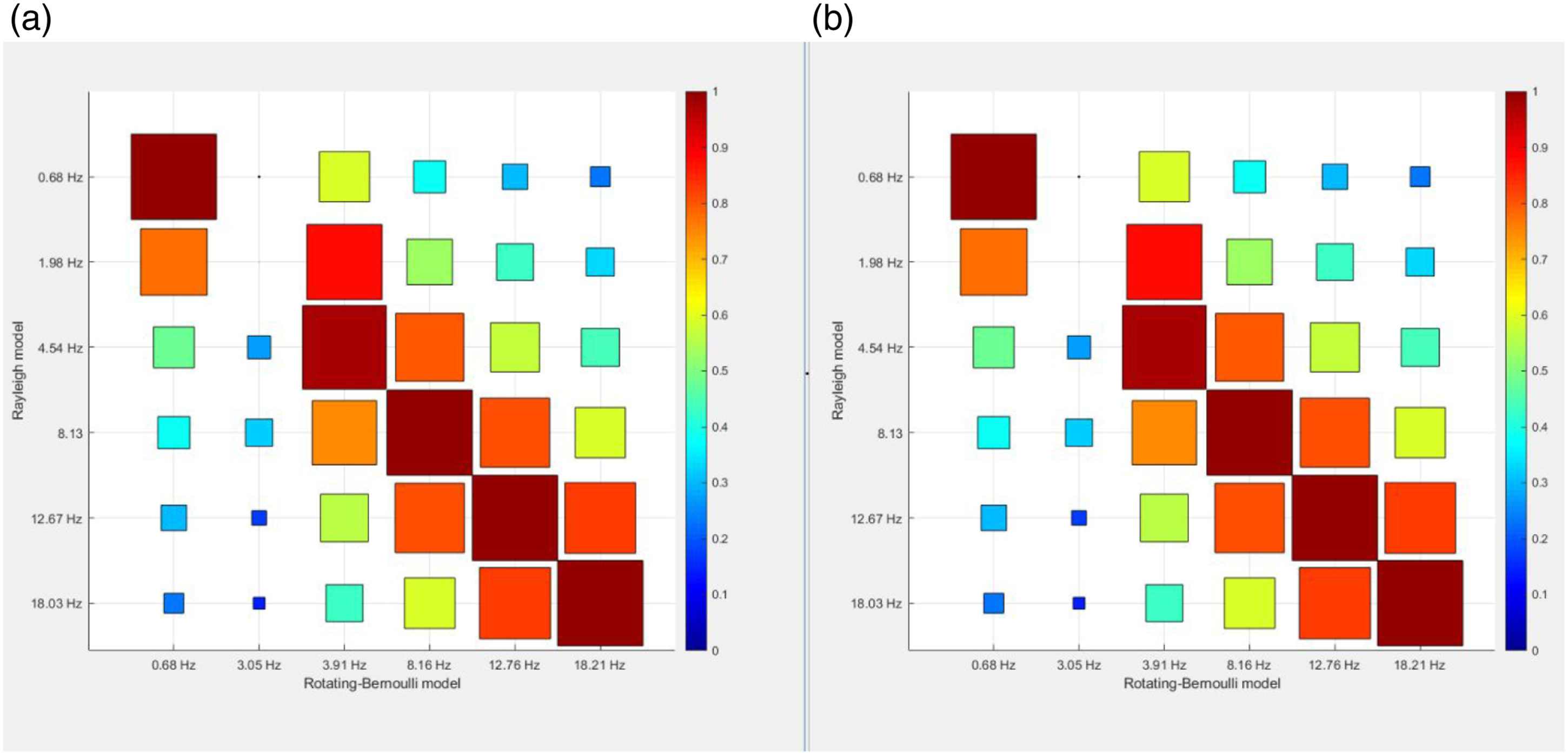
Conclusion
The flap-wise vibration of the NREL-5MW HAWT blade was investigated. All the blade parameters are included in this study, such as the centrifugal force, gravitational axial component, rotary inertia, pitch angle, pre-cone angle and hub radius. Subsequently, the Rayleigh, Timoshenko, rotating and non-rotating Bernoulli theories are used with the same model, same blade geometry, same material properties and the same choice of degrees of freedom as an effective way to make a clear comparison between them. The aim is to develop an accurate model that has clearly explained that for precise condition monitoring, a comprehensive dynamic model ensure the accuracy in determining the natural frequencies and corresponding mode shapes. The comparison procedures between the chosen models are based on the modal data. According to the obtained results, the following points are concluded: 1. Comparison of natural frequencies is made by tabulation of all chosen models results. The similarity of natural frequencies has been confirmed. The results clearly indicate that the free vibration analysis in the flap-wise direction is approximately the same in the case of the Rayleigh method and the model, which includes the blade control angles such as the pitch and pre-cone angles. Also, the results showed that increasing the angular velocity has a significant effect on the natural frequencies, whilst the influence of increasing the hub radius has less effect. The pitch and pre-cone angles have minimal influence on the natural frequencies. An important conclusion is that Bernoulli theory does not produce accurate results. 2. The second way to compare the theories is by plotting the natural frequencies for each mode included in the comparison. The frequencies values plot of the Rayleigh method with blade control angles effect versus the Rayleigh without the control angles effect are exactly coincident along the lone 3. The comparison between the mode shapes is performed by plotting the deformed shape of each adopted theory along the blade span and overlaying the plots on each other for the first six mode shapes to show the points of similarities and differences. The mode shapes figures show a similarity in the fundamental mode where it has the same path line in all adopted theories. The discrepancy was clearly noticed in the second and third modes of Bernoulli and rotating-Bernoulli. However, this agrees with the discrepancy in natural frequencies in the same modes and confirms that the rotary inertia significantly impacts second and third modes. 4. Another way that is adopted to compare the different mode shapes is by making x-y plot. This comparison was convenient to verify the Rayleigh model, where all individual points on the plot lie close to the straight line passing through the origin. Also, there is the inconsistency of Timoshenko versus Rayleigh in the first six mode shapes plot in the case of angular mode shapes, which indicates the influence of shear deformation. 5. In the goal to reinforce the conclusion and to validate the most accurate model, many different types of comparison were achieved and not just to rely on one. The MSF indicate sensitivity as an index, and the deviation of the corresponding mode shapes can be adopted to compare the effect of different parameters. The comparison between the mode shapes using MAC provides a measure of similarity of the pair-wise eigenvectors/mode shapes. Using The MAC index gives the same conclusion, and the shortcoming of Bernoulli theory in the first and second modes is clearly noticed. The MAC index indicates the correlation in the Timoshenko mode shapes values compared with Rayleigh. Useful means of quantifying the degree of correlation between different theories. The Timoshenko theory has the influence of angular mode shapes, which indicates the effect of shear deformation to predict the vibrational behaviour of wind turbine blades and their dynamic characteristics.
Footnotes
Declaration of conflicting interests
The author(s) declared no potential conflicts of interest with respect to the research, authorship, and/or publication of this article.
Funding
The author(s) received no financial support for the research, authorship, and/or publication of this article.