
Abstract
Inspired by the bite and swallowing function of a snake's mouth, a robot end-effector grabbing mechanism was designed. The grabbing movement is realized by the ‘bite’ function of the bionic snake mouth actuator, and the ‘swallowing’ function insures a continuous grip on the object. To implement the continuous grip function of the new robot end-effector, the complex motion of a snake's mouth is simplified into three basic movements based on the anatomy of a snake's mouth and with a combination of bionics and engineering. The upper jaw consists of a double four-bar linkage mechanism and the lower jaw mechanism implementing a lateral expansion function are the two elements of the robot end-effector. The relationship model and the corresponding curves of the actuating force and gripping force are necessary to implement an open-loop control of the robot end-effector. Through analysis and simulation, linkage parameters are determined to implement the desired motion.
1. Introduction
Most of the present robot end-effector grabbing mechanisms are performed by clamping devices and cannot work effectively within small operating spaces because of size limitations. For example, the robot end-effector used in minimally invasive surgery can only clamp one object at a time and is not applicable for the continuous clamping of a smooth edged object. Besides, after surgeries of areas such as the gall bladder, ovary, spleen, appendix and tumour, doctors need to remove pathological tissue from the patient's abdominal cavity and keep its edge and kernel complete as much as possible at the same time. Sometimes in order to obtain an accurate diagnosis of a disease, a complete sampling of tissue fluid is also required for further effective staining and slice tests.[1-2] Therefore, a new robot end-effector grabbing mechanism which can perform continuous grabbing of a smooth object is needed. In this paper, a new bionic design method[3] of a robot end-effector grabbing mechanism was proposed, inspired by the bite and swallowing function of a snake's mouth.
The structure of a snake's body has some very novel features from an engineering perspective. A snake can swallow prey 3 times the volume of its mouth, for the upper and lower jaws can generally open as wide as 150 degrees while a human's can only 30 degrees. Therefore, the study of robot end-effector grabbing mechanisms based on a bionic snake's mouth has important significance in scientific research and fields of application, meanwhile, the study of animal anatomy and the kinematics of mechanisms are the theoretical basis and research approaches for this study of a bionic snake's mouth.
2. Anatomy and mechanism of the snake mouth
The structure of a snake's skeleton is different from other animals and this makes a snake's mouth able to expand to 3 times its volume. The quadrate, ectopterygoid and the pterygoid connect the upper jaw to the lower jaw and can move independently, therefore the lower jaw can open a wide range, generally more than 150°. Besides this, the lateral bones of the jaw are connected by muscles and ligaments and can move independently from each other while other animals' are usually joined as one part at the front of head and cannot move separately [4–10]. This flexibility of the snake skull makes the snake's mouth able to open a wide range not only vertically but also laterally. The upper jaw connects to the lower jaw by the quadrate and the lower jaw can be separated into the right and left sides in order to expand its mouth capacity for larger prey.
Due to the loose connections of the jaw apparatus, a snake's mouth can swallow its prey in a special and flexible way. The actual kinematic displacement of the jaw is controlled by ligaments, articular surfaces and muscular activity, at the same time the skin of a snake is smooth and of great elasticity, making the snake's mouth able to open wide in order to swallow bigger prey. Figure 1 shows the morphology of the elements of a snake's skull [11].
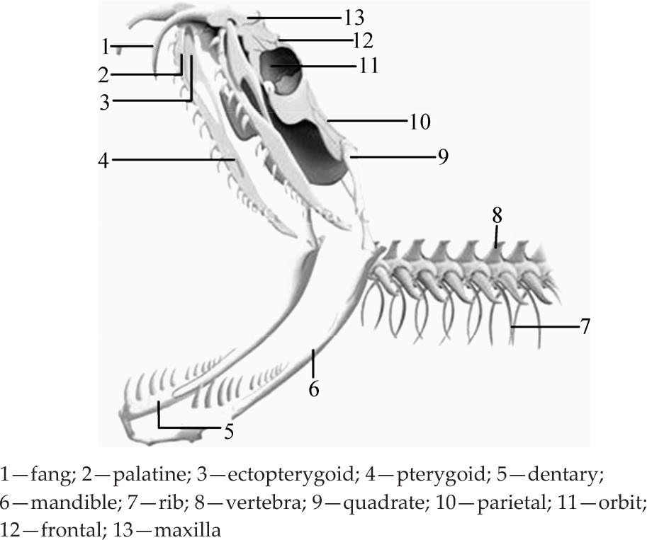
Morphology of snake skull elements
The skull of the snake connects to the quadrate and rotates at the front-end of the quadrate within a certain range. The bones of the upper jaw apparatus can be considered as a closed loop linkage mechanism and the motions of the upper and lower jaws are relatively independent. Kardong[12] took the rattlesnake as a representative object of study and abstracted the jaw apparatus to a multi-linkage mechanism connected by joint hinges, as shown in figure 2.

Schematic diagram of rattlesnake mouth
3. Mechanical principle of robot end-effector grabbing mechanism based on bionic mouth
3.1. Mechanical diagram of the bionic mouth end-effector grabbing mechanism
The aim of the end-effector grabbing mechanism is to imitate the bite and swallow motion in order to implement the continuous grabbing of smooth objects by combining bionics and engineering together. Based on the main functioning of a snake's mouth, we divide the predation process into two parts: the first part is the open and bite motion of the snake's mouth. In this part the upper jaw and lower jaw move up and down respectively, the lower jaw stretches laterally to expand the inner space of the mouth and at the same time the quadrate moves upright to the pterygoid in order to erect the fang to hook the prey. The other part of the predation is the swallowing movement with which the prey is dragged into the mouth by the hook-shaped fang and the pterygoid is driven by the motion of the quadrate.
The mechanism consists of two parts: the grabbing mechanism and the steel wire-driven flexible manipulator. The mechanical diagram of the grabbing mechanism is shown in figure 3.

Mechanical diagram of the grabbing mechanism
3.2. Mechanical principle of robot end-effector grabbing mechanism based on bionic mouth
As is shown in figure 3, the upper jaw apparatus can be simplified into a bilaterally symmetrical four-linkage mechanism. Taking the left part of the mechanism as example, the bionic mouth grabbing mechanism is connected to the flexible manipulator by the rotation centre D. Bar 4 lifts when the mouth opens, meanwhile, the lower jaw opens downwards. Bar 1 swings on the axis of the connecting points D, driving bar 2 and bar 3 to carry out the opening and biting motion of the fang of the upper jaw. Then the swallowing motion is finally carried out and the object is dragged into the mouth. The lower jaw mechanism consists of bar 5 and bar 6 which are connected to the upper jaw by revolute pair E to carry out the opening and closing motion of the lower jaw. Bar 5 and bar 6 are connected by revolute pair F, which is perpendicular to the axis of the revolute pair E. Bar 6 implemented the lateral stretching and retracting of the lower jaw. Generally, the left and right parts of lower jaw of a snake's mouth are joined together by muscles and ligaments in the front and could stretch laterally for bigger prey. As this separable jaw apparatus is hard to implement with mechanical connections, bar 6 is made into an L shape with an arc-slot in the front. The left and right parts of the lower jaw are laterally symmetrical and joined by a revolute shaft. The whole grabbing mechanism is covered by an elastic material similar to snakeskin. With the movements of the mechanism, soft and smooth objects can be successfully grabbed and held.
The motion of the grabbing mechanism and the flexible manipulator is conducted by steel wires. Therefore the manipulator can make miniature shapes and has high flexibility, and is especially suited for use in conditions of restricted motion space such as minimally invasive surgical sampling. One end of the steel wires is fixed to the bars by screws; the other end passes through the guide pulley on D and the guide holes on the base component and connects to the remote operating motors. The revolute pair D is connected to the base and has pulleys on the axis. The corresponding steel wires on the two sides of the grabbing mechanism are bilaterally symmetrical and driven by the same motor; this will not only allow the inner space of the bionic mouth to be as large as possible but also ensure the correct coordination of its movements. As is shown in figure 4, each end of the flexible joints is controlled by three steel wires and the wires are evenly distributed by 120°. The steel wires are embedded in the edges of the joints in order to control their motion. The driven motor exerts a torque at the end of each flexible robot and the driven force is assigned out by cover components at the end of the robots. Then the flexible robot can bend and the grabbing mechanism at the end of the manipulator can reach desired positions by changing the length of the corresponding driven steel wires.

Schematic diagram of the steel wire-driven flexible manipulator
4. Analysis and simulation of the robot end-effector grabbing mechanism based on bionic mouth
The main concepts in the design of the bionic mouth grabbing mechanism are 1) the structure should be simple and compact and applicable in a limited operating space; 2) the motion and control should be as flexible as possible and have enough degrees of freedom; 3) it should allow for the continuous grabbing of objects with smooth edges.
4.1. Working process of the bionic mouth grabbing mechanism
The parameter of the grabbing mechanism is 24mm×10 mm×6.5 mm when it is closed and when it is completely open the height and the width reach 53mm and 16mm respectively. The grabbing mechanism can open up to maximum of 150°. The outside diameter of the flexible manipulator is 13.5mm, thus the grabbing mechanism mounted on the end of the manipulator can pass through small wounds in minimally invasive surgeries. Figure 5 shows the working process of the bionic mouth grabbing mechanism and in this paper we take the grabbing of a soft ball with a diameter of 18mm as an example.

Working process of the bionic mouth grabbing mechanism
First, the grabbing mechanism should be small enough when retracted and the flexible manipulator long enough and have sufficient degrees of freedom in order to pass through small holes in the abdomen and get into the body smoothly(a). When it is about to grab the object the steel wires driven by the remote motors pull bar 1 and bar 4 upwards and bar 5 downwards and at the same time bar 6 stretches laterally to expand the volume of the bionic mouth (b), then the object is grabbed and bar 4 moves downwards, extends the fang bar 3 while bars 3, 4 and 6 hold the object(c). Bar 3 moves forward and backward under the drive of bar 1 and with the dragging of a barb-like tooth on bar 4 and the squeezing of the bars the object will eventually be ‘swallowed’ into the grabbing mechanism and taken out from the patient's body (d,e,f).
4.2. Position and orientation of the flexible robot
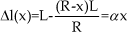
The flexible manipulator discussed here is a two-level flexible robot with 4 degrees of freedom. In practical applications the degrees of freedom can be increased by adding flexible robots to the manipulator. Three steel wires are needed for every one more flexible robot and at the same time increasing the wires will increase the difficulty of controlling the whole robot. Figure 6 is the schematic of a single flexible robot bending. We assume the bending is a compression process, L and D are the original length and diameter of the flexible robot, R is the curvature radius and α is the bending angle in radians, x is the distance from the point on the cross-section to the uncompressed outer end AB, then the length of arc CD is:
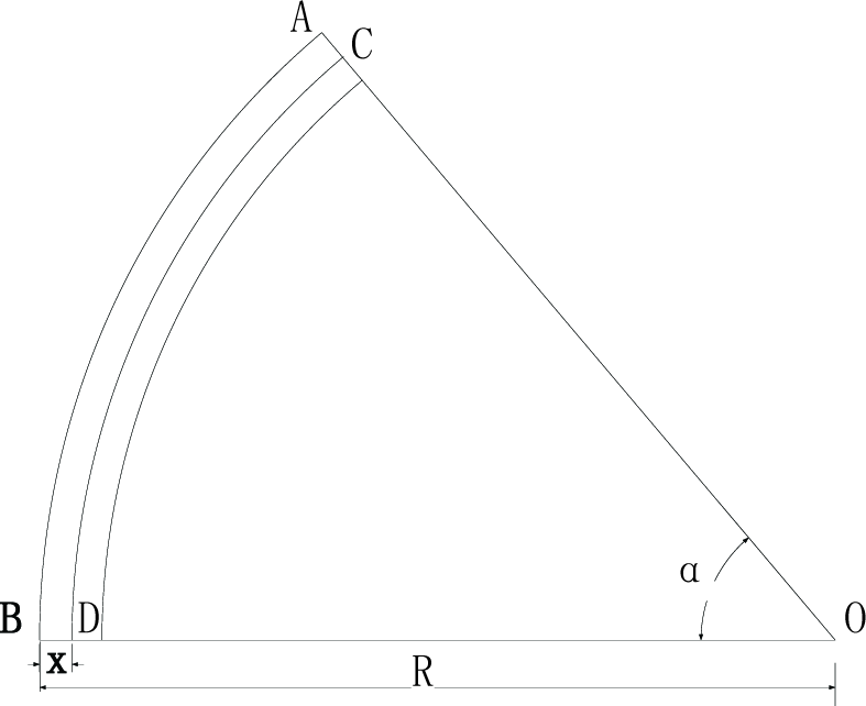
Schematic of single flexible robot bending

The amount of compression of arc CD is the required traction distance of the motor:
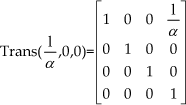
The bending movement of the flexible robot is controlled by changing the length of three steel wires. The base component is named joint 0, the first flexible robot is joint 1 and the second flexible robot is joint 2, Pi is the orientation matrix of joint i, see figure 7. then the transfer matrix from joint i-1 to i is:

Translation of single flexible robot
Rotate angle θ around the z-axis (the bend direction of the flexible robot):

Move l/α along the x-axis (the bend radius of the flexible robot):
Rotate angle α around the y-axis (the bend angle of the flexible robot):
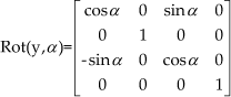
The transfer matrix is:

The orientation transfer relationship from flexible robot joint i-1 to i is:

The transfer matrix from joint i to the base component is:

Then the overall orientation transfer matrix is:

4.3. Static analysis
In this paper the static analysis of the process of grabbing spherical objects is carried out as follows. Due to the symmetrical structure of the grabbing mechanism, the left part is disused in a two-dimensional analysis. Figure 8 shows the static model of the grabbing mechanism and the model is simplified as follows: 1) as there is no high-speed movement in the application of the bionic mouth grabbing mechanism, inertia force and impact loads are ignored; 2) the grabbing mechanism is already in the static state of the grabbing process and the forces are balanced; 3) the tension of the steel wire is equal to the driving force provided by its motor; 4) friction is ignored. According to the Newton-Euler equation, for planar linkage mechanism of linkage number N:

The static model of the grabbing mechanism

Where
The equation of static equilibrium of the mechanism model is:


Where,
F1, F2, F3 - the counterforce to the grabbing mechanism.
T1, T2, T3 - the pull force of the steel wires exerted on the mechanism.
Fix, Fiy - the counterforce of each revolute pair.
θ0, θ1, θ2, θ3, θ4- degrees between linkages and the x-axis.
θT1, θT2, θT3 - degrees between the direction of the steel wires and the linkages they are connected to.
d1, d2, d3 - vertical length from the revolute centre to the direction of the steel wire on the linkage.
lT1, lT2, lT3 - vertical length between the revolute centre and the point where the steel wire mounted to.
Then the relationship between the driven force T1, T2 and T3 and the grabbing force F1, F2 and F3 can be obtained from the known conditions and the equation of the static equilibrium. Besides, in order to ensure that the object can be swallowed into the mouth successfully, the condition that degree θ between F1 and F3 should not less than 180°, is:

Where, R is the radius of the object to be grabbed.
4.4. Simulation analysis
Without considering the friction, we obtained the relationship between the drive force of the steel wire and the grabbing force by means of simulation. When the object to be grabbed is determined, that is, R is set, we can obtain the relationship curves of the ratio of F1 and T1 varying with θ4-θ0. When lT1 and the radius r of the pulley on D have different values, we get different curves. Where, θ4-θ0 is the degree between bar 5 and bar 1. The bigger F1/ T1 is, the higher the transfer efficiency of the drive of the steel wire and the easier it is to drive the mechanism. As shown in figure 8, we can conclude that the ratio of F1 and T1 reaches its maximum when θ4-θ0 is between 60°~86°, in addition, the ratio and the transfer efficiency become smaller when θ4-θ0 becomes bigger.
Figure 9-a shows the relationship curves between F1/ T1 and θ4-θ0 when the radius of the pulley is at 2.5mm and lT1 is of different values. We can conclude that F1/ T1 increases with the increase of lT1, that is, the transfer efficiency of the drive of the steel wire improves. However, when lT1 is bigger, the ratio of F1/ T1 decreases fast with the increase of θ4-θ0 and the grabbing force F1 will be more unstable. In figure 9-b, lT1 is 4mm while the radius r varies. The relationship between F1/T1 and θ4-θ0 shows that when r is at 2.5mm to 3mm, the grabbing force F1 is more stable.
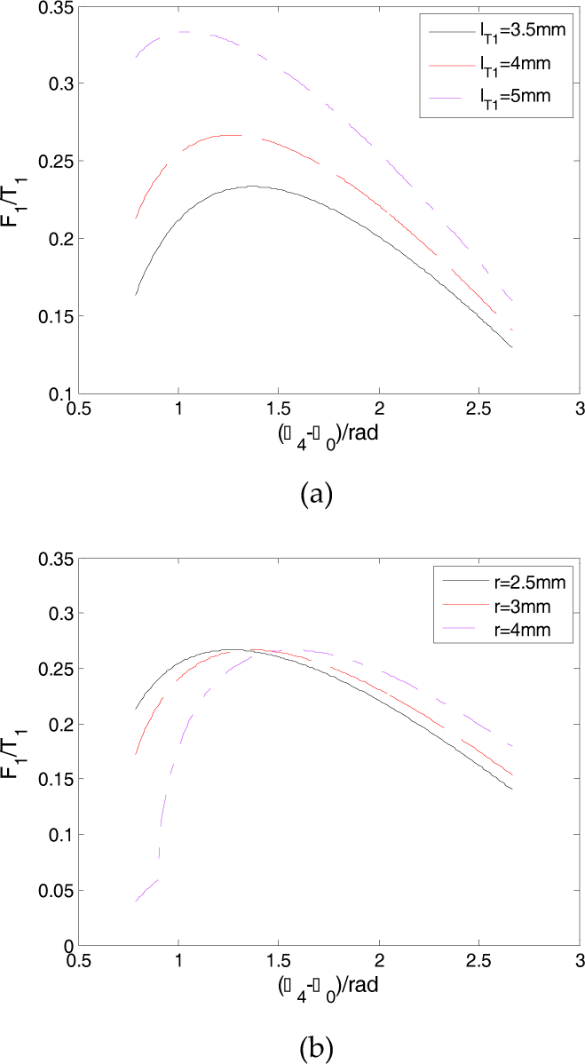
The relationship curves between T1 and F1
Figure 10 shows the relationship curves between F3/T3 and the angle of bar 1 and bar 4. In figure 10, F3/T3 increases when the connecting point of T3 has different values. From the curves we can see that the grabbing force is larger and the efficiency is higher when the angle of bar1 and bar4 is between 58°~80°. The efficiency of the drive force T3 is at its maximum when the angle is about 70°.

The relationship curves between T3 and F3
5. Summary
The robot end-effector grabbing mechanism based on a bionic mouth is designed by means of a combination of bionics and engineering. The relationship model and the corresponding curves of the actuating force and gripping force are discussed and an analysis and a simulation are conducted, linkage parameters are determined and the desired motion is implemented. As it is controlled by steel wires, the grabbing mechanism is compact, simple, flexible and especially fitting for small-scale situations and those requiring remote-control like sampling in minimally invasive surgery.
Footnotes
6. Acknowledgments
This work was partially supported by the Research Fund of State Key Lab of MSV, China (Grant No. MSV-MS-2010-03), the State Key Laboratory of Robotics and System (HIT) (Grant No. SKLRS-2010-ZD-06) and the National Natural Science Foundation of China under Grant No. 61075086, 60875058.