
Abstract
Water Strider Robot (WSR) is a kind of bio-inspired micro robot that can stand and move on water surface via surface tension. In this paper, a design method is presented with algorithms for designing driving leg. Structure, control system and software of the robot are also discussed in details. A prototype Water Dancer II-a that is driven with two electric motors is presented as successfully tested in lab. The proposed WSR is tele-controlled with infrared signals and has the capability of turning and speed regulation with features of light tiny volume and low power consumption. Experimental results are reported and discussed to show practical feasibility of the presented WSR prototype. The new results in the paper are related also to the WSR prototype design with a robot body of less than 30 × 30 mm size and with ten leg rods of 90 mm length and 0.2 diameter that are able to provide lifting force for a water walk of the 6.0 grams robot at a forward speed of 20 cm/s or angular velocity of 9 degree/s with two micro DC motors(RoomFlight 4 × 8 mm, 28 Ohm).
Introduction
Biology has amazing performance of fulfilling complex and dexterous operation with compact and efficient inner structure. Copy this kind of ability with novel mechanisms is currently a big challenge of engineering. At the same time, biologically inspired system is a great means of developing advanced novel robotic mechanisms. Therefore, there are many researches focused on the bionic robot.
On the view of different contact media, most of current micro robots can be catalogued as ground type (insect, snake, etc.), under water type (fish), and air type (micro-flyers). But Water Strider Robot (WSR) is unique because as a bionics copy of the insect water strider, it stands and moves in this unique way of locomotion by surface tension of filamentary legs. This makes it save greatly energy because avoid from the water viscous drag, that is the main resistance to hinder the boat, submarine and fish-like robot. WSR can also access to very shallow water, where boat, submarine and fish-like robot can not go. Moreover, it can be expected that tiny drag, high speed, great agile and small disturbance to the water. Some researchers imagine that the water strider robot could be used on any water without huge wave and even amphibious in the future. With a chemical sensor, it could monitor water supplies for contamination or other toxins; with a camera it could be a spy or an explorer; with a net or a boom, it could skim contaminants off the top of water (Forbes, 2004).
However, water strider robot needs to be built so light and so compact because the supporting surface tension is usually small. It is really a big challenge to develop. Prof. M. Sitti of CMU said to Forbs (Forbes, 2004), “I think it is the final challenge of microrobotics if you can make this thing.” In the field of design and fabricate technology of micro machine, some kinds of tiny micro-robot can be developed by utilizing MEMS and other technologies. For example, Monsieur (Miyazawa, O., 1993), composed of watch motor and toothful gears, has only 4.3g. A micro pipeline robot has only 0.3g was developed by Japanese company Denso (Kawakita, S., Isogai T., & Ohya, N., 1997). However, in the field of micro robot, onboard controller is still a mission impossible. Most of current micro robots suck power and control signals through cables. Those cables bring big limitations. Some technologies like microwave power transfer is developing, but only fit for special circumstance (Shibata, T., Sasaya, T., & Kawahara, N., 1998). Therefore, system integration is one of the key problems of developing WSR, namely the technology to integrate driver, controller, energy and sensor together into a micro weight and tiny size WSR.
Till to now, only few of WSR prototypes were successfully developped. The first one is the Water Strider of MIT (Hu, D., Chan, B., & Bush, W., 2003). It has 6 wax-covered legs made of Φ0.2mm stainless steel. Because powered by a simple elastic thread, it can move 20cm with 5 steps each time. The 2nd one is the Water Walker of CMU (Suhr, S., Song, Y., Lee, S., & Sitti, M., 2005) that was made by the group of Prof. Metin Sitti at Sept. 2004. It has a half-inch boxy-body made of carbon fibers that weight totally about 1 gram. It have 6 legs, each is 2-inch long and was covered with water-repelling plastic. The driver composes with 3 flat-plate piezoelectric actuators. This brings a disadvantage of the actuators are powered by wires and controlled by three circuits connected to a power supply. Namely, Water Walker is a system not independent but with wires. The 3rd one is the Water Dancer (Wu, L., Ding, L., & Guo, D., 2008) that was developed by Wu Licheng and his undergraduated students at 2005. Its legs were made of Φ0.2mm stainless steel thread and processed with hydrophobic nanoscale materials. It use micro-motor powered with battery button and 3 class gear reducer. Those earlier WSRs are still very simple, without the capability of turning and speed tuning. Then in 2007, new generation WSR of CMU is proposed (Song, Y., & Sitti, M., 2007). It has 12 supporting legs to increase support capability. It is non-tethered and driven with two electric motors. It can be set into two moving modes: go straight or wheel. But it is still uncontrollable.
Besides those, a simple model is also built at Columbia University (Basso, B., Fong, A., Hurst, A., & Knapp, M., 2005). Japan scholar H. Takonobu etc. developed a tethered prototype driven with Shape Memory Alloys (Takonobu, H., Kodaira K., & Takeda, H., 2005). The paper focuses on how to mimic the water strider's muscles with a mechanism. Gao etc. (Gao, T., Cao, J., Zhu, D., & Zhi, J., 2007) developed a prototype with 6 buoys. But it is in fact a kind of boat but not a WSR because buoyancy but surface tension is used to support the machine. The state of the arts of theory, technology and system development about WSR is detailed introduced, and then, some future key research directions, key technologies and the prospects are pointed out in (Wu, L., Sun, F., & Yuan, H., 2010). Recently, a WSR using Circular Footpads, called STRIDE II, is also reported in (Ozcan, O.; Wang, H.; Taylor, J. D. & Sitti M., 2010). STRIDE II uses 12 circular concentric supporting footpads, each 42 mm in diameter to achieve big lift capacity. However, those footpads bring also big drag resistance that may make the WSR lost its biggest advantage.
In this paper, a recently developed new WSR prototype named Water Dancer II-a is reported. The presented WSR is driven by two micro-motors and is powered by two battery buttons. It can turning and change speed according to the infrared instruction from a remote controller. Moreover, a set of algorithms for designing and fabricating the robot is proposed. The performance of this kind of prototype is experimentally tested in lab.
Stucture Design
Architecture
The architecture of Water Dancer II-a is shown in Figure 1. The body of the robot has two layers: electric board and base board. The base board is made of a sheet of tung wood and used as the base of the robot body. The electric borad is closely glued upon the base board. A battery holder with a button battery, and two DC motors are glued upon the electric board. Another button battery is glued to the underside of the base board. The two driving legs for driving the robot are glued on the motor shafts one by one (in fact on the shaft sleeve, namely a gear tight fitted on the shaft), while ten supporting legs clinged zygomorphously on underside of the base board. In order to obtain stable movement, all those parts of the robot is symmetric distributed and the center of gravity of the robot is tuned to the center of the body by selecting carefully the place for each part. The robot is remote controlled with infrared signals generated by a special developed controller as shown in Figure 10.
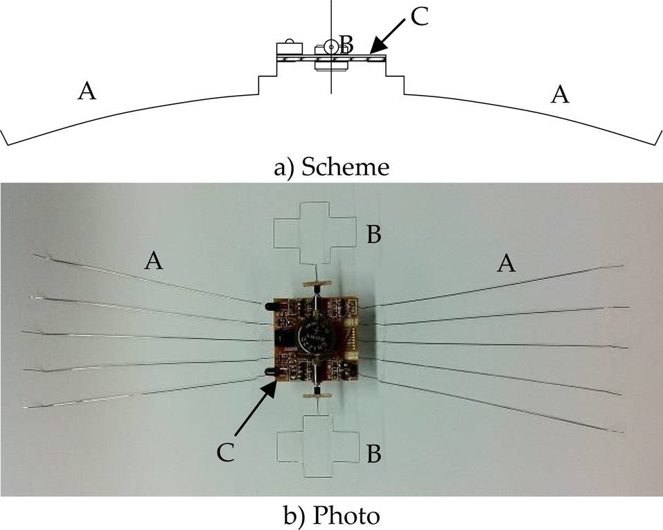
Scheme and photo of a developped Water Dancer II-a: A-Ten supporting legs; B-Two driving legs; C-The body with a base board, an electric board, two batteries in their holders, and two DC motors.
The driving leg is directly linked with the motor shaft. The design objective of the driving leg is the maximal driving efficiency, namely to get maximal propulsive force through the driving leg's revolution. The driving leg is made of Φ0.2 mm stainless steel thread and covered with hydrophobing agent to make the leg has a water-contact angle of 120 degrees. The littte square filled with bias as shown in Figure 2 at the right side is a little bar of tung wood, that is used to glue the leg to the motor shaft easily.
Shape Design
Because of weak supporting capability, to eliminate any rotational imbalance during operation is very important for a WSR. The proposed design permits to fine tuning the shape of the driving legs by push or pull the leg at the four corners a, b, c, d as shown in Figure 2. This can be used to compensating the manufacturing errors, assembly errors and maintenancing the dynamic balance during the use age. The other reasons and advantages that the cross framework is proposed are:

A scheme of the driving leg in B of Figure 1.
cross framework is a kind of symmetry close frame that can assure the rigidity of the driving leg to ease vibration and deform of the leg. a leg can push water twice per turn, this apparently can improve the duty ratio of the motor. the leg's driving part that contact with the water can have an available distance from the robot's body to ease the wave disturbance on the supporting legs.
As shown in Figure 3, the radius of the motor is 2 mm and the thick of the body of the robot is about 1 mm while the height of the supporting leg is 12 mm (see also Section 2.3). For avoiding from viscosity resistance, the driving leg should not break the water surface while revolves. Let max depth of the driving leg has a safe space ha from the the supporting legs to assure the driving leg would not break the water surface. The max permissible draft of the supporting legs with water-contact angle of 120 degrees is 3.86 mm (Wang, S., & Wu, L., 2010). Therefore, the height of the driving leg should be design as 28 mm by choicing ha as 1 mm.

Vertical position to the the water surface.
Moreover, width of the driving legs, in fact the length of the active part of the driving leg that contact with the water dg (as shown in Figure 2) should also be carefully designed. According to (Bush, J., & Hu, D. L., 2006), as a robot with the scale as a water strider, magnitude of drag force created by foot of driving leg can be estimated by the following equation,

where ρ is the density of water (1000 kg/m), V d is the speed of the driving leg sculling the water, A is the characteristic area of the body, w is the characteristic width of the body, and γ is the surface tension coefficient (0.072 N/m). The first term is the form drag, which results from the pressure differential generated across the driving leg. The sencond term is the curvature forces, which corresponds to the surface tension force.
As shown in Figure 4, A = d g >w. Therefore, Eq. (1) can be transformed as
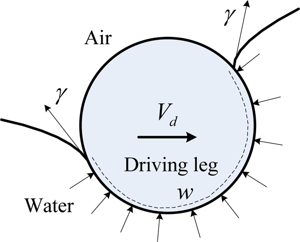
Section of the driving leg is sculling the water.

According to Eq. (2), d g is longer, the driving force is bigger at the same rotation speed but the power of the motor needs more large. Therefore for assuring that the driving leg can effectively overcome the drag force to turn, especially from the rest status to start turning, d g is design as longer as possible according to the maximum power output of the motor,
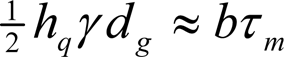
where b∊[0,1] is a safety factor.
Let b=0.7, d g is design as 10 mm while the max output torque of the motor is 120 μNm. The other sizes of the driving legs can be designed by making shape of leg a symmetrical cross as shown in Figure 2.
The design objective of the supporting legs is to provide the WSR with the maximal supporting force that is crucial to the stableness and safety of the water surface moving. The relationship between supporting leg's length and supporting force is discussed in (Song, Y. S., Suhr, S. H., & Sitti, M., 2006), a shape design method for the supporting legs is also proposed according to the principle that to have a compliant leg that straightens up at the maximum loading. But the method in (Song, Y. S., Suhr, S. H., & Sitti, M., 2006) based on the assumes that deformation of the leg is small, while a WSR should uses acerose legs those deformed great. Moreover, the lift force is calculated through fitting the experiment data, which also affects the precision and practicability of the method. Therefore, for calculating the precise optimal shape of the supporting legs, a new method based on curved girder model is proposed in (Wu, L., Wang, S., Ceccarelli, M., Yuan, H., & Yang, G., 2011).
The supporting leg is made of φ0.3 mm stainless steel thread and covered with hydrophobing agent. The structure of the supporting legs of Water Dancer II-a is shown as Figure 5. The main (middle) part that will contact with water is carefully figured a special curve to form a straight line when the leg presses the water most (Lian, Z., 2010). This design lets all the surface tension convert to supporting force. On the other hand, the coherence is very important to keep equal press on each supporting leg to prevent a leg pierce the water surface first. The ladder-like fore-end of the supporting leg is specially designed for tuning the coherence of the height and direction of 10 supporting legs. And ladder-like end is beneficial to fixing the leg to the body. The tail end is turned up to prevent the end from breaking the water surface.

Structure of the supporting leg.
Water Dancer II-a is equipped with 10 supporting legs those are equably layed out on underside of the body in size of 30 mmx30 mm as shown in Figure 6.
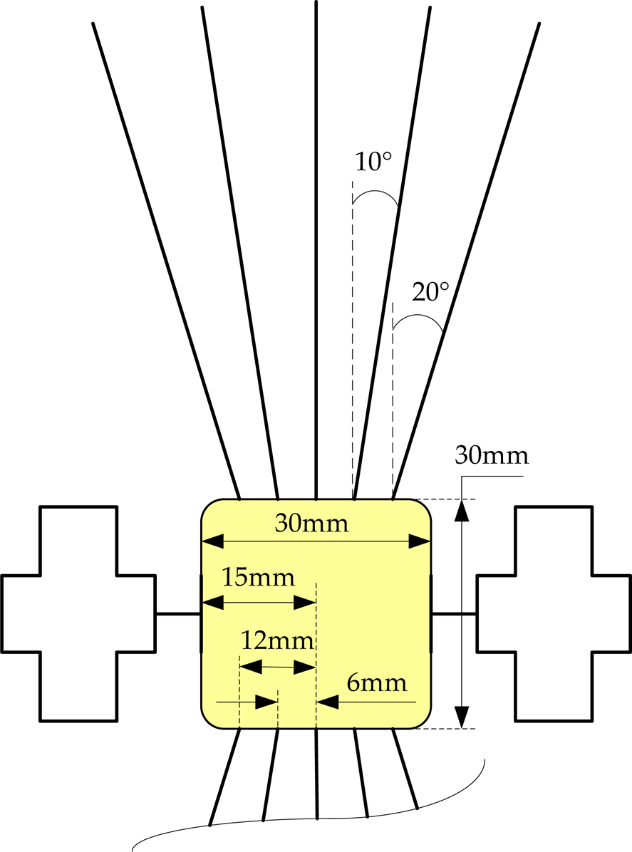
A layout diagram of the supporting legs.
The scheme of the control system of the Water Dancer II-a is shown as Figure 7. The control system consists of a controller, a power module, an infrared communication module, a motor-driving module and a remote controller. Batteries on board are equipped to supply controller and the motors. Infrared communication module receives and decodes infrared signals from the remote controller and then transfers to controller. The controller will control the motors through the motor driving module to obtain expected move of the robot. The proposed WSR is driven with 2 DC motors. A special remote controller is built for generating infrared instruction signals. For saving the weight, a thin film board is developed as shown in Figure 8.
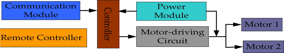
Scheme of the control system.

Photo of the electronic board with the control system, a battery and two DC motors: A-integration infrared receiver for receiving remote control signals; B-DC motor; C-Button battery in its battery holder.
First of all, a low consumed power MSP430F1121A is adopted to be the controller.
For ensuring the electric stability and reliability, the motor and the other elements are supplied independently. The power module have two 3V button batteries. A CR1620 supplies motors while a CR1220 supplies the controller and the drive circuit.
The infrared communication module is consists of a receive part and a send part. The receive part is adopt with a 38B type integration infrared receiver chip. The chip has an inner high frequency filter circuit to filter the carrier signal (with 38 KHz) to demodulate and output the original digital code.
The motor-driving module is used to receive the control instruction and then control the WSR's move through the 2 motors. The motors of Water Dancer II-a are DC vibration motors that weight 0.5g each. H-Bridge Motor Driver circuit as shown in Figure 9 is used to drive the motor. The motors are driven with 2 PWM routes that are outputs from the controller. Each motor can stop, run in right direction or contray direction indepently. And motor speed can be tuning through changing dutyfactor of the PWM signals. Therefore, the robot can run forward, backpedal, make turn and circling at a point in different speed.

H-Bridge motor drive circuit for one DC motor.
As shown in Figure 10, the remote controller has four buttons. Double click of the upward button is also defined for enter into or quit the speed tuning mode. A chip of MSP430F1121A is adopted to be center controller. When a button is pressed, the remote code of the key is sent immediately. The remote code is amplitude-modulated serial code. The remote code is modulated with 38 KHz carrier frequency and is then transmitted through the infrared emission diode using baud rate of 1 kbps. The carrier signal is generated by software. Two red LEDs. are used as indicator lights while the power is two double A batteries.

Photo of the remote controller.
The robot has two programs to be written, namely the remote controller program and the control board program. Both programs are developed with C code under the MSP430's development tool IAR Embedded Workbench. The remote controller program fulfills the functions of coding, modulate and transmit of the remote control signals. The control board program decode the infrared signals, judge which button is clicked, and dominate the robot's moving mode through Motor Drive Circuit. The flow charts of the two programs are shown in Figure 11.

Program flow chart: a) remote controller program, b) control board program.
As shown in Figure 12, the developed prototype Water Dancer II-a can stand well by surface tension on the water, while all the legs are tuned to have nice cohenrece.
The validity of the proposed design methods and the prototype is verified with some experimental tests. The robot is put on the surface of water after the control board is powered by closing a switch. Then the robot can action according to control signal of the remote controller. The robot can operate according to control signals of the remote controller. Experimental tests have been carried out in a lab water pool of 1.75 × 2.75 m with 1 cm water depth. The tests have aimed to validate robust operation of the prototype in several conditions, such as forward motion, turning motion, different locomotion velocities. In particular, during the tests some parameters have been measured to characterized the successful operation such as velocity, and supporting leg adaptation. Velocity has been measured both for forward translatory motion and angular turning motion. The supporting leg adaptation has been evaluated as referring the initial manual placing of the robot on the water surface with some sinking of the leg foot that has been measured only by visual inspection. Few millimeters of sinking have been still possible for starting an efficient motion of the prototype. Those tests have been also useful to set up a final robust operation layout of the prototype with capability of several motion trajectories by remote programming and extra payload.
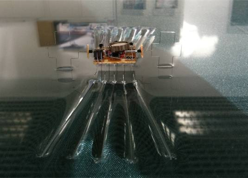
Photo of the Water Dancer II-a standing on the water.
For testing load capability of the developed robot, a body with only supporing legs is used as shown in Figure 13. The photo shows that the robot can bear 2 dimes of rmb, more than 7.5 grams totally with the body (1 gram). While a full robot weights about 6 grams, potential load capability of 1.5 grams is reached. This is good for the safty of the robot's moving on water.

Test the load capability of the robot.
The straight motion is tested in different speed under the control of a remote controller. The snapshots of the robot moving in the maximum speed are shown in Figure 14. The maximum forward speed is measured to be 20 cm/s.

Snapshots of the robot moving forward in speed of 20 cm/s.
The robot can turn by using different speed at the left and right driving leg. Figure 15 shows the general right turn of the robot. Figure 16 shows the robot turn at a fixed position by using reverse speed at left and right driving leg. The maximum angular velocity is measured to be about 9 degree/s.

Snapshots of the robot turning right.

Snapshots of the robot turning at a fixed position.
Water strider robot is a kind of bio-inspired micro robot that can stand and move on the water surface via the surface tension of filamentary legs just like water striders. In this paper, the design method of this kind of robot is discussed. A set of algorithms for designing the size of the actuating leg is proposed. The methods and an instance to design the structure, control system and software of the robot are present. A developed prototype driven with two electric motors is introduced and experimentally tested. The prototype tele-controlled with infrared signals has the capability of turning and speed governing.
The proposed design of the shape of the driving legs permits to fine tuning the shape of the driving legs. This is successfully used to compensating the manufacturing errors, assembly errors and maintenancing the dynamic balance during the use age. The relationship between the drag force of driving leg and the max output torque of the motor is built. The driving legs are properly sized according to the relationship. The supporting legs are successfully designed to let the robot stand and move on water surface via surface tension of filamentary legs just like water striders. The ladder-like end design of the supporting legs is availably tuning the coherence of the 10 supporting legs of Water Dancer II-a. Through ingenious system integration scheme, Water Dancer II-a presents the feature of motor-driven, non-tethered and tele-controllable with an electric system attached to a thin film board in size of 30 mm × 30 mm and elements of weight totally less than 5 grams. A special infrared remote controller is effectively developed too.
WSR is a new hot research area. Current prototypes are still primary and can only work in the laboratory. The problem of lifting was solved by using five legs per side with a biomimetic design, while the locomotion is given by two paddle driving legs with a direct actuation from DC motors. The power efficiency with floating robustness provide also payload capability that with experimental tests has been estimated as 25% of the robot weight.
Compared to other reported WSR (please see the details in the Section 1), Water Dancer II-a shows better performance in the lab test.
Contributions of the paper can be considered in the design explanations and experimental validations of a successful new WSR microrobot prototype.
Certainly the parameters of the Water Dancer II-a are not yet optimized, and further works and experiments will be necessary improving the design and operation of the Water Dancer prototype.
Index to multimedia Extensions
Video-WSR-2011-3-1.mp4, video, a film of the developed Water Dancer II-a is making experimental tests of motion in a big water tank. Include the video segments of the robot is moving strightly, turing, turing at a fixed postion. forward-to-backward.mp4, video, a video segment of the developed Water Dancer II-a changes moving state from forward to backward.
Footnotes
8.
This work was supported by the Fundamental Research Funds for the Central Universities (0910KYZY52, 0910KYZD05), the key Project of Chinese Ministry of Education (No. 211212), NSFC projects No. 60875062, and Joint Construction Project of Beijing Municipal Commission Education 104-00102211 – Key Technology Research on Beijing Public Safety Information Inspecting Platform.