
Abstract
The standard EN ISO10218 is fostering the implementation of hybrid production systems, i.e., production systems characterized by a close relationship among human operators and robots in cooperative tasks. Human-robot hybrid systems could have a big economic benefit in small and medium sized production, even if this new paradigm introduces mandatory, challenging safety aspects. Among various requirements for collaborative workspaces, safety-assurance involves two different application layers; the algorithms enabling safe space-sharing between humans and robots and the enabling technologies allowing acquisition data from sensor fusion and environmental data analysing. This paper addresses both the problems: a collision avoidance strategy allowing on-line re-planning of robot motion and a safe network of unsafe devices as a suggested infrastructure for functional safety achievement.
1. Introduction
Workspace sharing by human operators and industrial robots (IRs hereafter) poses significant challenges and is gathering increasing attention from both industrial and research communities. Among many technological aspects, safety represents the core problem. Safety can be, in fact, transposed in terms of either functional safety addressing the functional reliability in design and implementation of devices and systems, or algorithms for safety, allowing monitored cooperation tasks among robots and humans. Both features are equally essential in the design of industrial applications. Nevertheless, safety options provided by the basic supply of IRs are still quite limited or unavailable, sometimes hindering the possibilities of safe design of cooperative industrial tasks. Only advanced features, i.e., including safety modules, appear to be open to interaction strategies, although not completely flexible in the integration of different sensor apparatuses and/or algorithms. This is partly due to the limitations in available reference standards for IRs in cooperative contexts, reflecting the complexity of the collaborative scenarios, especially when involving physical interaction with users.
In such an articulated scenario, this paper narrowly focuses on how to safely monitor and track the position of users within a collaborative IR workspace and how to assure a safe collision avoidance strategy in such a workspace. This contribution is dedicated to both introduced aspects of functional safety and algorithms for safety.
Besides the technical content of the paper, this work aims to emphasize a new approach for managing collaboration in IR applications, where manipulators are just nodes in a wider network of devices, computational agents and communication-data providers/consumers. Such a network happens to be the pivot element of a design methodology that has the objective of assuring safety and high-performance levels, regardless the safety grade (e.g., SIL3, PL e) assigned to single devices.
The structure of this paper mirrors the twin set of safety features (functional and algorithms), moving from a global point of view (the cell as a complex system, Section 2) to a local point of view (specific procedures that enable workspace sharing, Section 3).
Section 4 describes in detail a feasible framework that could guarantee safety at both levels and Section 5 reports experimental results of such a developed set-up.
2. Collaborative Workspace Safety-Monitoring
A recent trend in industrial robotics shows the introduction of collaborative robotic methodologies capable of safe behaviour in unstructured dynamic environments, reflecting the advances in service robotics, where lightweight solutions specifically designed for physical Human-Robot Interaction (pHRI) entail a new class of interactive devices (e.g., KUKA LWR, ABB FRIDA). For years, both the research [1–4] and the industrial [5–6] communities have made significant efforts in extending the collaboration domain between robots and operators in industrial robotics. This trend reflects a strategic roadmap of industrial robotics towards a more integrated and safe environment, where sensing is pervasive and control methodologies include safe cooperative modules. Industrial robotics appears to have adopted new methodologies, fields of application and technologies for service robotics, in order to ultimately overcome the current rigid procedures and work towards a cooperative, freely shared workspace.
At the same time, there is a remarkable growing effort in standardization, in order to define the regulatory basis for cooperative environments and interaction modes in real applications. Emerging standards, to which the ISO Technical Committees are providing a wide definition background, can play a significant role in broadening the range of advanced applications in workspace sharing and human-cooperation covered, especially by industrial robotics. However, the path to standardization is, of course, very articulated, with the most recent standards (e.g., [7][8]) defining cooperation modes (see Figure 1), but without specific implementation guidelines.
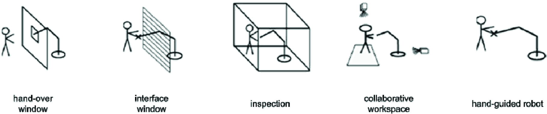
Cooperation task typologies drawn from Appendix E (pp. 53/54) of the Standard EN-ISO10218-1/2011. Reproduction of these images is courtesy of UNI Ente Italiano di Unificazione, Via Battistotti Sassi 11/B Milano tel. 02700241
On top of the consolidated standardization ecosystem related to machinery and robotics [7–13], the concept of functional safety is of particular relevance for the aspects of algorithms and architectures that are in the scope of the present discussion. Functional safety is the “part of safety relating to the EUC (Equipment Under Control) and the EUC control system that depends on the correct functioning of the Electric/Electronic/Programmable Electronic (E/E/PE) safety-related systems, other technology safety-related systems and external risk reduction facilities”[12]. This standard acts as a foundational regulation for many integrated robotic systems because of the pervasive presence of programmable electronics, which makes a robotic cell a device itself and whose functional safety involves an extended set of actions aimed at assuring proper functionalities. Therefore, safety is clearly an integrated notion, whose logical, procedural and technological aspects are distributed among hardware (devices), software (algorithms), and networks.
Safety features of devices are probably among the most addressed by technology providers because of a consolidated regulation [9,10,13] and, as stand-alone components, limited requirements in terms of integration that could hinder the safety certification grade.
Algorithms are instead poorly addressed, often being limited (in either standards or industrial practices) by bare machine stops, while scientific literature has proposed behaviour strategies for robots in the presence of risky conditions since decades. In particular, one of the most prominent classes of strategies is represented by collision avoidance algorithms (see Section 3). Collision detection and motion re-planning represent the best option for IRs in collaborative workspaces, up to now.
IRs display a limited usage in cooperative interaction tasks, notwithstanding the reduced speed required for accomplishing such tasks. Collision avoidance-based motion planning, instead, has historically been and is designed for providing a class of collaborative tasks, where cooperation is mainly translated in terms of relational co-presence in the same workspace. The integration of such algorithms is therefore likely to require a massive amount of sensor data exchange over a network (necessary for workspace detection and supervision) introducing architectural issues in terms of information flow, protocols and transmission performances. The networking aspect poses demanding requirements in terms of integration, because in articulated architectures, like in Networked Control Systems (NCS, [14][15] see Figure 2), robots and sensors have to be monitored together with the network itself. The safety notion is extended to the introduction of safe protocols, which are required in sensor interfacing, robot control, and automation fieldbuses [16][17][18]. Many efforts in introducing safe protocols into the main families of buses can be seen in recent years [19][20][21][22].

Robotic Networked Control System (NCS). Safe-grade nodes (CPUs and sensors) are represented in yellow; CPUs can run different OSs, including non-real-time tasks; sensors are eventually clustered in subnets (e.g., sensor fusion agents).
However, safety technology appears to be far from a seamless integration of safe devices and protocols in complex architectures for collaborative workspace tasks. The main reasons are due to the costs of safe-grade devices, the limited extension of the possibilities of interfacing, the absence of safe-graded frameworks for complex robot application and the limited performances of safety devices.
Meanwhile, one developmental approach can involve the extension of the concept of functional safety to the integration level of robot applications, removing the hard constraints of an exclusive usage of safe-grade devices and protocols, introducing in this way the concept of a safe-net of unsafe nodes.
The core idea is to obtain functional specifications in terms of reliability and robustness through a multi-layered multi-crossed architecture, where any safety-relevant information can be reasonably labelled as safe after a data verification procedure over the network. This is mainly achieved through distributed redundancy; data double-checks from different sources and layered verification routines that reduce the probability of failure in detecting inconsistencies.
3. Collision Avoidance Strategy
3.1 Related Work in Collision Avoidance
Collision avoidance is basically a set of procedures for rearranging the robot motion in the presence of dynamic obstacles, specifically humans. Such procedures therefore involve both motion planning and the control of the resulting motion [23]. However, a split approach to such components can be observed [24]. In a dated, but still valid, survey [25] Hwang presents four major approaches to motion re-planning. The “Skeletons based Planning” maps the motions onto a network of one-dimensional lines and a motion and planning problem becomes a graph-searching problem [26][27]; the “Workspace Decomposition” splits the path in a sequence of connected cells [28][29]; the “Potential Fields” imposes a virtual force field that guides the robot motion [30][31]; finally, “Mathematical Programming” consists on looking for a path that optimized pre-defined goal-functions [32]. In [33], Harden suggests each of such methods relies on determining distances between a manipulator and other objects in its environment. Although distances are directly sampled from sensor measurements (lasers, sonar, etc.), they must fit a model of the environment in order to have meaningful representation. Flordal in [34] proposes the use of Discrete Event Systems (DES) and of the supervisory control theory to synthesize control systems. This solution should be applied in interaction tasks where human operators occupy only a limited portion of the workspace and their movements are repetitive and possibly foreseeable. Unfortunately, such assumptions are not met in a large number of applications, making safe interactions through planning and control very important. In [35], Perry claims that collision prevention and optimization of the robot configuration to avoid obstacles can be the only option for non-redundant manipulators and that planning approaches are well suited only for achieving a goal position in known static environments.
Among the others, the Artificial Potential Field approach [30] is one of the historically most important and feasible methods for IRs. The core idea is that obstacles and targets are equivalent to generators of virtual potential fields and the motion is the evolution of its dynamics, imposing externally the corresponding virtual repulsive/attractive forces that act on the links as the real gravitational forces.
Reactive motion behaviour in dynamic and unstructured environments is therefore based on real-time knowledge acquisition of the environment, based on local information by suitable sensors, which is translated into potential fields. Unfortunately, as in [36], this approach does not guarantee stability in target reaching and the behaviour of the robot could be unpredictable. Contrarily, probabilistic methods in motion planning [37] can be applied to problems of high complexity and are dedicated to a more correlated accomplishment of both motion planning and motion control. Similarly, the elastic strip framework [38][39] allows the integration of task-oriented dynamic controls and motion coordination techniques, as in [40] and [29]. Recently, new approaches plan the motion on the basis of danger indexes (DI, formulated as product of distance, velocity and inertia factors) as in [41]. The DI is used to generate a repulsive force similar to artificial potential forces proposed by Khatib [29] and move the robot to a safer place in case of danger. The human operator has of course been considered as an obstacle and most of the modelling effort has been devoted either to avoid any collision or to stop the robot if no option for avoidance remains available.
3.2 Finite State Machine for Management of Robot Behaviours
The general approach to the implementation of a collision avoidance strategy includes the identification of (i), in which cases re-planning algorithms are needed and (ii), to which part of trajectories they can be applied.
Therefore a finite state machine (FMS) with three superstates (see Figure 3) is modelled:
Safe Area - where the distance between the operator/objects and the robot is larger than a pre-imposed boundary threshold
Warning Area - where the robot could end up in a collision but the relative distance allows the execution of safe avoidance control algorithms
Danger Area - where the distance is shorter than the one associated to a high collision risk.

Finite State Machine (FSM) with three super-states: humans can be inside Safe, Warning, and Danger Areas. The system is initialised in Danger state; Warning and Safe states have nested FSMs for processing motion planning according to the conditions elaborated from sensors. The collision avoidance strategy takes place only in Warning state.
For conservative approaches, the initial state has to be the most critical one, with the option to move to safer states if allowed. Entering the warning state can happen when safety sensors detect an intrusion, or a previous unsolvable collision condition (robot stop) expires. The default actions associated with such transitions involve a speed reduction to the standards-imposed 250 mm/s. Then the IR activates the collision avoidance algorithm itself.
Considering the part of trajectories upon which such task can be executed, a set of application-related constraints affect the algorithm allowance/performance:

Application-related constraints
Hence, the development of any generic collision avoidance algorithm has to suite various constraints sets and be easily integrated into standard IRs controllers.
3.3 Grids of “pass-through” for On-Line MotionRe-Plan
On calculation, the suggested algorithm consists of a cloud of safe-points (points that are safely achievable by the robot, with respect to static obstacles) that lie around the nominal trajectory (defined by the user). At each time step, in case of detected potential collisions, the motion re-planning updates the target position selected among such pre-calculated points. The selection of new target points has the objective of keeping the robot moving. Conversely, collision avoidance strategy is applied only if the velocities of the dynamic obstacles are limited, otherwise no re-planning is possible with acceptable robot behaviour. In addition, user-perception of the robot movement is important and modification of the trajectory that is too fast should cause negative (and unforeseeable) user reaction. Such operations are performed by two different modules: an off-line pre-processing of the workspace and an on-line control strategy. The off-line module manages two different problems: (i) modelling static obstacles, (ii) computing a set of points that are safely reachable by the robot and can be used as via-points when the user-programmed trajectory must be re-planned to avoid collision.
3.3.1 Static Obstacles in Workspace Modelling
In [42] authors proposed an algorithm for the analysis of the workspace, based on its conversion in an STL CAD file format. Starting from an acquisition of the workspace, this module computes a STL model of the environment where the original objects' surfaces are offset and corners are smoothed, in order to obtain a safe description of the work cell (objects' envelopes are larger than actual objects). Once the mathematical model of the workspace objects is available, the idea is to generate a virtual force field with two sources: (1) each element of the STL and (2) the end stop of the joints. Denoting as

A detailed description of the algorithm generating such forces is provided in [43].

Collision avoidance algorithm: (a) definition of a polar grid of pass-through points reachable for the robot at each node of the nominal trajectory; (b) virtual repulsive forces on a generic point P due to the model of the environment (static obstacles); (c) virtual repulsive force due the presence of a human (dynamic obstacle) passing through the workspace. Re-planned robot target is selected among the grid of pre-calculated (acknowledged) pass-through points.
3.3.2 User-Programmed Path Decomposition
This module aims at generating feasible solutions to re-planned motion, to be easily implemented in industrial scenarios (excluding fancy trajectories) and exploit IRs' controller functions. The module decomposes the trajectory programmed by the user within the IR controller in a grid of “pass-through points” (a set of points safely achievable by the robot at different instants) and automatically generates the new program for the IR.
First, the algorithm transforms the nominal trajectory (a user-defined continuous sequence of linear, circular or spline segments) in the nominal path (a sequence of discrete nn points {
3.3.3 On-Line Processing: Avoidance Algorithm
At runtime humans can be considered as “dynamic” obstacles, that is, obstacles whose movements are only partially known at the moment the trajectory has been programmed. A suitable description of humans in the workspace can be obtained through a collection of several points on the body surface. When the minimum distance among the moving obstacles and the trajectory is greater than D (warning distance), no avoidance algorithm is applied. If it is lower than d (danger distance) task execution is suspended see Figure 4-c). Each dynamic obstacle is a source of repulsive force and for the generic k-th position of the dynamic obstacle, the repulsive force
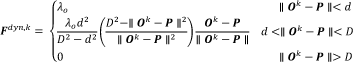
Where

Once the repulsion direction frep is obtained, the new target is chosen among the available points belonging to the grid of pass-through points on the basis of two criteria:
Maintain a distance among the TCP and the obstacles greater than the minimum distance d;
Denoting escape direction as the axis along which the robot is imposed to move in order to avoid the collision, the target point is selected among the pre-calculated grid in order to minimize the dot-product between the escape direction and the projection of the resultant force
In order to achieve good robot behaviour, the control algorithm has to perform a fast response to avoid the obstacle, but also has to assure a predictable response according to the human operator perception, i.e., the trajectory change has to be smooth. The reduction of the execution task velocity, modifying the speed override ovrobst, could be a suitable solution in cases where this is allowed.
The algorithm calculates the override on the basis of the distance between the obstacles and the TCP and the obstacle's velocity. Denote as λ
k
dist
the term that takes into account the distance between the fe-th obstacle and the TCP, denote as λ
k
vel
the term that takes into account its velocity and denote as vobstMIN the minimum obstacle velocity, so that if the actual speed is smaller, no velocity reduction is applied. Therefore, the speed override ovr = ovr(

where ovrmin is the minimum override velocity. As a general consideration, the suggested algorithm aims to allow an easy implementation of the algorithms in IR available program languages.
4. Framework for Safe Workspace Sharing
The execution of safe collision avoidance algorithms relies on measurements from distributed sensors that return obstacles' positions and motion. In a robotic NCS (see Figure 2), such sensory information is, in general, provided by a heterogeneous set of sources, including the sensors themselves, and different computational agents for the elaboration of spatial information and possible comparisons with stored data, i.e., databases. The execution of such procedures, in fact, is very unlikely to be performed only by standalone safety-grade devices. Instead, a network of general devices, including unsafe ones, is the general architecture that can be found in collaborative workspaces. Accordingly, a solution that should provide the safe integration of collision avoidance strategies in IRs consists of designing a network that integrates both safe and un-safe sensors and where the robot is just one of several nodes.
The methodology proposed here makes use of a framework (see Figure 5 and Figure 6) where a safe network of unsafe devices is built for distributing several layers of data crosschecking and validation, in order to reduce the probability of missing any detection of faults. In terms of functional safety, the robotic NCS is considered as a device itself and all its parts have to be validated with respect to their contribution in the overall assessment of a safe behaviour. Equivalently, components in a NCS are not required to be safe per se, but their data are required to be validated and monitored online.

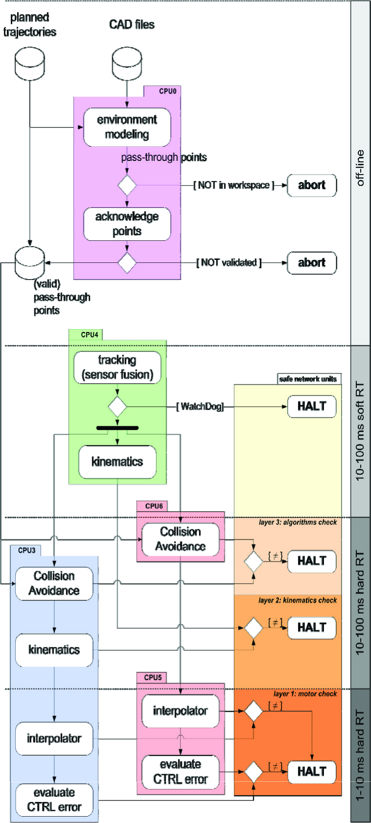
Implementation of safety framework for collaborative workspace with collision avoidance: trajectory-relevant information is available offline, where the static part of obstacle detection is elaborated and acknowledged. Such information is retrieved at runtime by the collision avoidance tasks for re-planning purpose. Sensor data sample online at CPU4 are available for doubled data flows and data evaluation on different nodes (CPUs 3, 5 and 6) for all the 3 safety layers. Consistency check (diamonds) for all data from all nodes takes place on the pool of architectural and safe CPUs (1, 2 and safe). Safety layers and timing are displayed in gradient colours, getting darker for faster cycle times and for lower-level scope of data. Timing (grey strip) is indicated with ranges (depending on applications) and requirement for soft/hard real time.
4.1 Building Redundancy from Architecture: Procedural and Infrastructural Dimensions
In terms of architecture, the proposed framework concurrently supports such a functional validation, along both a procedural and an infrastructural dimension (see Fig. 5). Procedurally, functional data related to a robot moving inside a collaborative workspace are computed and evaluated for consistency by redundant processing units. All algorithms are twice independently processed. From an infrastructural perspective, instead, data to be evaluated are distributed in redundant flows for independent data dispatching. In fact, each computational unit dedicated to independent data processing (i.e., procedural redundancy) distributes its data flow to two independent computational units, each of which relays data flows to the final safe unit (i.e., architectural redundancy).
This method is used in order to take advantage of the safe channels (redundant, CRC-independent) that are available at the final safe unit (safe I/O in Figure 5). Such node is ultimately in charge of activating safety countermeasures in case of any inconsistency, either from the procedural or the architectural redundancy. In this case, a controlled halt routine and, if necessary, a power cut-off are activated by a uniquely required safe node.
4.2 Data Elaboration in Redundant Channels
The architecture for generating redundancy among unsafe devices/units enables safe evaluation of the actual data dedicated to collaborative workspace sharing. Such evaluation is distributed along three layers (see Figure 5 and Figure 6) devoted to different levels of time/scope/granularity:
The consistency check of the planning and the execution of the (re)programmed trajectory
The coherence check of motion data tracked from redundant measurement systems
The consistency check of the collision avoidance execution.
4.2.1 First (motor-level) Layer of Safety Verification
The first safety layer is the bottom-most verification that the robot works correctly (i.e., what has been programmed is what the robot is executing).
The robot controller has to run a number of watchdog-monitored checks for joint rates, control errors and interpolated end-effector positions. These features are usually included in IRs and also have to be implemented in different processing units able to access low-level (hardware/drivers level) data from the robot. Some advanced robot controllers provide fast-channel access to motion data. Such procedural duplication in motor checks is due to the absence of SIL3/PS-e safety grades. Internal redundancy would, in this case, very much affect the hardware supply, due to the introduction of redundant CPUs and sensors on both the manipulator and the control unit. Watchdog timings, control error boundaries and speed limits are pre-defined (see subsection 4.4).
4.3 Second (manipulator-level) Layer of Safety Verification
The second safety layer is devoted to the validation of the robot end-effector (and/or an alternative link along the robot) kinematics using different motion sensors (i.e., the robot is where it is supposed to be). The same trajectory is computed from the robot forward kinematics and from external motion sensors (e.g., visual tracking, inertial navigation). End-effector poses or single points on the robot arm are then compared from both measurements.
The resulting error (Euclidean distances [44]) is then checked against a predefined (see subsection 4.4) accuracy threshold εs that depends on:
the calibration inaccuracy εc that is due to real misalignment between the external sensors and robot coordinate frames (Euclidean distances have to be computed in the same frame),
any undetected/un-modelled compliance of robot mechanics that causes the real position of the links carrying the sensor to be different from the nominal one provided by the joints sensors, introducing the inaccuracy εt,
the temporal misalignment εt of position sampling introduced by the latency of transmission of signals in case of asynchronous buses,
the intrinsic inaccuracy of each sensor εsensors.
4.4 Third (workspace-level) Layer of Safety Verification
The third safety layer is the verification of robot positioning, with respect to the human workers (i.e., computation of collision avoidance strategy for the human co-operator). The on-line strategy suggested in Section 3 provides a runtime re-planning of robot trajectory passing through a predefined set of acknowledged through-points (see subsection 4.4).
4.5 Assuring Functional Safety Throughout the Framework
All layer evaluations are executed as consistency checks of motion data computed by the different (redundant) units from robot-joint level to environment level, during motion execution (online). Nonetheless, current motion data (to be checked for consistency in each layer) are also validated online against safe intervals that are pre-set offline before the motion execution, in an acknowledgement step of the framework. Equivalently, the consistency checks between redundant nodes are architecturally/procedurally implemented for the specific purpose of increasing the safety level of the intrinsically unsafe nature of the motion data evaluation computed in any single (unsafe) unit. Each unit, acting in each evaluation layer, verifies that motion data are within given safe intervals, while such unsafe computational results are twice independently doubled for upgrading their reliability, minimizing the probability of undetected errors. Intervals and/or accepted regions for motion data verifications are, of course pre-set. Therefore, they do not functionally belong to the safe-validated infrastructure. The acknowledgement of safe regions by an operator (see Figure 5), before motion execution, allows all data involved in verification and consistency checks to be considered safe (under the operator's responsibility and with the acknowledgement of safe conditions currently compatible with standards, e.g., reduced speed), as in [45].
List of the processing units integrated in the framework. CPU7 has been used in order to simulate the acquisition of various sensors in the cell.

5. Test-bed Implementation
The robot used in the collision avoidance application is a serial robot COMAU NS16 (6 dof, and 16kg as payload, see Figure 7-a).

(a) Layout: a dummy is moved in the collaborative workspace through a linear axis (dynamic obstacle entering the Warning area). (b) The safety-box with two PLCs (CPU1 and CPU2) and the SafeCPU. Two safe-I/O modules are integrated in the safety-box for safety devices (e.g., emergency stop) and for connection to safety/power circuit in robot drivers. (c) UML Deployment Diagram of the test bed (detailed description in Section 5).
The robot controller provides the C4GOPEN real-time high-rate (500 Hz/1 kHz) communication channel that, among others functionalities, allows mirroring of, to an external PC, both the actual robot position and the actual target processed by its motion interpolator.
User-programs are instead processed by a second internal PC and motion programs are written in PDL2 (Pascal-like) proprietary language.
Remarkable functionality, provided by the interpreter of the user-programs, consists of the availability of standard UDP/IP (and TCP/IP) sockets to a standard ISO/OSI Ethernet network. These channels allow an easy integration of the collision avoidance algorithms through the standard functionalities of the COMAU controller.
5.1 Physical and Functional Network Description
With reference to the infrastructural view of the system architecture in the Deployment Diagram of Figure 7 and units in Figure 6, the SafeCPU is a COTS PLC by B&R Automation whose functional safety is certified SIL3/PL-e according to IEC61508. The SafeCPU provides two communication channels allowing interfacing with external devices: a safe-certified Ethernet protocol (POWERLINK Safety© by B&R, proprietary standard) that allows the communication with certified safe digital I/O like electromechanical switches and a non-safe Ethernet port allowing communication through TCP/IP and UDP/IP protocol (POWERLINK, open source standard).
A safe-communication channel (i.e., POWERLINK Safety©) assures that any halt-event command, issued by the logic implemented in the SafeCPU, safely opens the emergency circuit. Conversely, data coming from unsafe communication channels (i.e., POWERLINK) are redundantly computed and redirected by two standard PLCs, namely CPU1 and CPU2. As displayed in Figure 7, each PLC implements different consistency checks on redundant data transmitted through standard UDP/IP through the Ethernet physical layer. Boolean results of data comparisons are sent to SafePLC that, in case of incoherence or negative occurrence, safely opens the emergency circuit. Programs running in the two PLCs provide equivalent functionalities, but are implemented by different programmers in order to fulfil the requirements of IEC61508. The implementation of the safety framework in Figure 6 displays a functional box containing the SafePLC, the safe I/O and the two PLCs, which are actually 3 different nodes in the physical system of Figure 7. Thanks to the redundancy of functionalities, the “box” can be therefore considered as a safe-observer of the data passing through the network.
Considering the left side of the Deployment Diagram in Figure 7, the functionalities necessary to guarantee supervised workspace sharing have been implemented in 4 different CPUs. 2 CPUs (namely CPU5 and CPU6) are the PCs available for the NS16 robot. One PC, namely CPU4, is devoted to the acquisition of data coming from sensors in the working cell. Tasks in CPU4 are watchdog-monitored on sensors data acquisition and are used for tracking both human and robot positions (see safety layer 2 in Figure 6), since COMAU NS16 does not provide redundancy measure of joint positions. The robot motion control, running in CPU6, communicates only with the real-time external PC, namely CPU3, through the C4GOPEN high-rate communication channel. In order to obtain complete calculation redundancy, CPU3 integrates a library that virtualizes the actual robot interpolator and computes the forward kinematic, in order to enable the collision avoidance strategies and to compare the robot position with measures coming from sensors (CPU4). Collision avoidance algorithms have been developed both in the user-programming language of the robot interpreter (that runs in CPU5) and in the external real-time PC (CPU3). Both CPUs send the results of the implemented strategy to the PLCs, which verify the consistency of the data calculated, while only the output of the algorithm running in the user-space of the robot is used by the robot motion controller. In addition, a second user-program in the robot controller sends the actual position of the robots, (the motion targets) cyclically through UDP/IP communication channel to CPU1 and CPU2.
Since the data payloads exchanged among the PLCs and the different nodes of the network are quite limited, UDP/IP connection has been preferred to TCP/IP because it guarantees a higher frame-rate, the probability of packet loss is limited due to dedicated local network and the data transfer acknowledgement is not required in presence of fault-tolerant applications on redundant consistency checks.
5.2 Minimum Reaction Time Enabling the Emergency Circuit
Considering the timing features of involved nodes (Table 2), it is possible to compute the nominal time between the detection of an emergency event and the actual emergency circuit reaction, taking into account the following constraints:
Incoherence between data coming from CPU-3 and CPU-6 requires a reaction time equal to 20ms (maximum communication time between CPU6 and CPU-1/2), plus the communication between the PLCs and the SafeCPU must be equal to 0.8ms, plus the SafeCPU execution time of 0.010ms, plus 50ms that is the time spent for the electro-mechanical relay to be opened. Hence, the total latency is about 72ms.
Incoherence in target generation is equal to the C4GOPEN communication time (1ms), plus calculation time (less than 20 microseconds), plus communication time between CPU-3 and the two PLCs (0.8ms), plus the communication time among the PLCs and the SafeCPU (0.8ms), plus the safe-relay reaction time (50ms). Hence, the event total latency is about 52ms.
Incoherence in following error calculation is equal to C4GOPEN communication time (1ms), plus communication time between CPU-3 and the two PLCs (0.8ms), plus the communication time among the PLCs and the SafeCPU (0.8ms), plus the safe relay reaction time (50ms). Hence, the event total latency is about 50ms.
Identification that an operator is inside the Danger-Area requires tracking sensors data elaboration (differing on the basis of the eligible hw/sw), plus the communication time between the CPU-4 and the CPU-3/6, plus the elaboration data time equal to time calculated in point (i). Under such hypotheses, the measurement system assures the object identification in 50ms and the maximum latency time for the emergency circuit reaction is about 102ms.
timing features of inter-nodes communications.

Globally, taking into account a watchdog on the data coming from sensors, a reasonable reaction time of the system is about 100ms.
5.3 Collision Avoidance Strategy implementation
Sizes of Safe, Warning and Danger areas have to be defined on the basis of two factors: (i) minimum reaction time of the system as in section 5.2 and (ii) maximum velocity allowed for a user entering the collaborative workspace.
Considering the maximum velocity allowed for the TCP by the standard ISO 10218 (250mm/s), the maximum space covered since the emergency signal is about 25mm. However, in real manufacturing operations, a robot moves in free workspace with an acceptable velocity of about 1m/s. Under this assumption, the maximum space covered since the triggering of the emergency signal is about 100mm. Considering anthropometric measures of an average human operator, a proper radius for a protective cylinder centred in his centre-of-mass can be assumed to be about 350mm. Hence, the radius of the Danger Area around the humans has been fixed to 500mm.
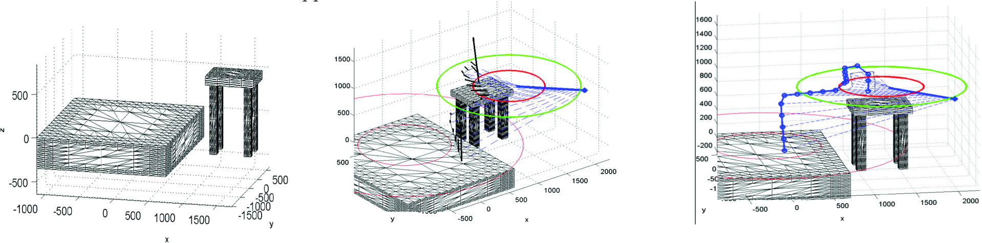
Two series of tests have been carried out. In the first test, the robot has to follow a path without getting very close to static obstacles (see Figure 8-a). In the second test, a more complex environment and trajectory are used (see Figure8-(b)). The two environments have been modelled through a MATLAB© toolbox developed by the authors and described in [43]. The position of the dummy is given by the motor position of a linear axis (see Figure 7-a).
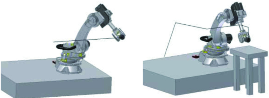
(a) Linear Trajectory and no static obstacles within the workspace (b) Complex trajectory and a simple static obstacle within the workspace

Experiment 1 (Fig. 8-(a)). Horizontal linear trajectory of 1,600 [mm], and the robot nominal linear velocity has been fixed at 1.000 mm/s. Four different approaches direction of humans have been tested.
A. No Forces exerted by the environment
The experiments have been performed imposing a horizontal linear trajectory of 1,600mm of static obstacles, i.e., the environment forces are negligible. The robot's nominal linear velocity has been fixed at 1m/s.
Test 1) The operator is approaching perpendicularly to the robot trajectory, with a linear velocity of 250mm/s. As in Figure 11, the robot keeps a safe distance from the human operator.
Test 2) The human is approaching perpendicularly to the robot's trajectory, with a linear velocity of 2000mm/s. Increasing the obstacle velocity does not introduce any appreciable change in the robot trajectory.
Test 3) The human is moving parallel to the robot trajectory in the same direction, with an offset of 400mm and with a velocity of 1.200mm/s. When the TCP goes into the Danger Area the task is suspended.
Test 4) The robot TCP and the human operator are moving in opposite directions. The distance between the robot and the obstacle quickly decreases (see Figure 11). When the distance decreases under a limit the correction due to the algorithm starts to deform the original trajectory. Note that the robot does not stop the motion and is able to avoid the obstacle.
B. Complex environment
The second test (Figure 8-(b)) is more complex as a structured environment is imposed. However, due to the limited workspace of the available robot, the experimental results are not exhaustive. Figure 10-(a) shows the STL model of the work cell and Figure 10-(b) displays the resulting force calculated, taking into account both the environment and the human operator that approaches to the robot. As shown in Figure 10-(c), the robot does not intersect the Obstacle Forbidden Zone close to the obstacle and the controller is able to re-plan a trajectory that correctly accomplishes the task. The speed reduction, modifying the override value, must be mandatory in order to have satisfactory robot behaviour.
Experiment 2 (Fig. 8-(b)). Complex Environment and Complex Trajectory. Forces calculation and actual robot motion.
6. Conclusions and Future Works
New technologies, devices and standards are posing challenging design and implementation shifts in the usage of industrial robots. The introduction of collaborative workspaces, where humans and robots can simultaneously work, sharing the work cell without physical fences, have deeply modified the way we think about the integration of robots on shop-floors. Nevertheless, safety options provided by basic supplies of IRs are still quite limited or unavailable.
In such a complex context, this paper has focused on how to safely monitor and track the position of users within a collaborative IR workspace and how to assure a safe collision avoidance strategy in such workspace.
This work shows how these two problems correspond to a new approach in robot cell design, where the HW/SW architecture has to assure the functional safety of the plant and the cell-controller must be provided with intelligent computational nodes where algorithms for safety run and modify the robot behaviour during the movement.
This paper proposes a safe-network of unsafe devices where the network architecture should allow the achievement of high-safety standards in terms of functional performance and of the necessary versatility and expandability in order to integrate nodes devoted to the elaboration of collision avoidance algorithms.
Within such a framework, this paper presents a particular collision avoidance strategy to be easily implemented in standard IR controllers and the final section is devoted to the description of a real test-bed implementation.
This set-up demonstrates the feasibility of the suggested approach, and the experimental results show that safe-collaborative workspace can be guaranteed with current standard industrial robot and IR controllers.
Footnotes
7. Acknowledgments
This work has been partially funded by ROBOFOOT European project, (FP7-2010-NMP-ICT-FoF).