
Abstract
A simple, robust nonlinear controller for quadcopters to avoid collisions, based on the geometry approach and kinematics equation, is proposed. The controller allows the quadcopter to avoid single and multiple obstacles. Once an obstacle with a high possibility of collision is detected, a boundary sphere of the obstacle is generated to determine the collision zone. Afterward, the tracking error angles between the quadcopter’s motion direction and the tangential lines from the quadcopter’s current position to the boundary sphere are computed to steer the direction of the quadcopter for collision avoidance. A guidance law and a velocity control law are obtained from the Lyapunov stability based on the tracking error angles and relative distances between vehicle and obstacles. In addition, a method to drive the quadcopter to the target position after the completion of collision avoidance is introduced. The effectiveness of the proposed collision-avoidance algorithm is demonstrated through the result of a numerical simulation.
Introduction
At present, quadcopters are used in a variety of applications. They are well suited for autonomously performing complicated civilian or military operations. However, because a low altitude is usually required in most of these missions, the issue of collisions between quadcopters and various obstacles is very serious and occurs frequently. Therefore, quadcopters must have the autonomous capability to avoid collision for safe and stable operation.
To solve this problem, various solutions have recently been reported in the literature. Many of them are inspired by path-planning algorithms. Chen et al. 1 proposed a path-planning approach for unmanned aerial vehicles (UAVs) with tangent-plus-Lyapunov vector field guidance to avoid obstacles. Richards and How 2 proposed a method to find optimal trajectories for multiple aircraft to avoid collision with each other. Budiyanto et al. 3 introduced a potential field to avoid collisions with obstacles based on optimal path planning. Lin and Saripalli 4 proposed a real-time path-planning method for UAVs to avoid collision with other aircraft or obstacles through motion uncertainty. In this method, collision prediction for UAVs is performed using reachable sets, and collision-avoidance path planning is generated through a sampling-based method. Several other studies related to the collision-avoidance ability for autonomous robot system can be found in the works of Dai et al. 5 and Rubio et al. 6 However, these methods are based on optimization techniques, which require intensive computation.
Another approach inspired by geometry was proposed in 1998 by Chakravarthy and Ghose, 7 who introduced a collision cone for collision detection and collision avoidance between two irregularly shaped moving objects with unknown trajectories. The collision cone is effectively used to detect the possibility of collision between a robot and an obstacle (in both static and dynamic environments). Also, recently Wang et al. 8 proposed a three-dimensional (3D) navigation strategy to reach a target position while avoiding collisions with obstacles based on the enlarged vision cone. Seo et al. 9 proposed a method to avoid collision for UAVs in formation flight. Zhiyong et al. 10 presented a method to equip UAVs with collision-avoidance capacity based on the minimum angle shift. Another collision-avoidance approach was proposed by Goss et al., 11 in which collision avoidance was realized between two aircraft in a 3D environment using a combination of a collision cone and the geometric approach. Shin et al. 12,13 presented an obstacle-avoidance method for UAVs based on differential geometry. Generally, these collision-avoidance algorithms seem to be simple and facilitate fast response with low computational requirements. However, most of them are limited to guidance laws, and the UAV’s velocity is considered constant throughout the flight time. Therefore, collision may occur if a UAV is in flight with a high velocity and the heading angular rate is limited in the control loop.
A more practical method for the collision avoidance of UAVs based on vision sensors has been developed by Gosiewski and Cieśluk. 14 In this method, the UAV avoids collision with obstacles based on the Lucas–Kanade method for estimating optical flow and gradient, which is implemented on a real-time embedded system. Fasano et al. 15 proposed a fully autonomous multisensor (radar and camera) anti-collision system for UAVs. Choi et al. 16 proposed a real-time mid-air reactive collision-avoidance system for UAVs based on a single vision sensor. Another interesting method is to mimic the human behavior of detecting collision using a monocular camera, as proposed by Al-Kaff et al. 17 Aguilar et al. 18 also proposed an obstacle-avoidance system for UAVs using the monocular onboard camera. These methods are the good solutions for collision-avoidance system. However, most of them are focused on the image processing techniques for detection and size estimation of obstacles.
The present study proposes a simple, robust nonlinear controller for quadcopters to avoid collisions based on the geometry approach and kinematics equation. Once an obstacle is detected, a boundary sphere of the obstacle is defined to determine the collision zone (or collision cone). The radius of boundary sphere is determined considering both the dimension of vehicle and obstacles in order to facilitate more rapid finding of avoidance angle. Afterward, the tracking error angles between the quadcopter’s motion direction and the tangential lines from the quadcopter’s current position to the boundary sphere are computed to steer the quadcopter in the left or right directions for collision avoidance. A guidance law and a velocity control law are obtained from Lyapunov stability based on the tracking error angles and relative distances between vehicle and obstacles. In this manner, both the heading angular rate and velocity of the quadcopter are analyzed and controlled simultaneously. The advantages of this algorithm are the ability to find the shortest path to avoid obstacles and reach the preplanned target position after completion of collision avoidance. In addition, the guidance and velocity control laws are considered simultaneously to ensure safe flights within speed and angular rate limitations.
Furthermore, this study proposes a simple and practical nonlinear controller and compares with other most advanced approaches 19 –21 with considerations of the implementation on a real-time embedded system. The proposed full control scheme consists of multi-loop architecture (i.e. outer loop and inner loop). The proposed algorithms for collision avoidance and approaching to the target position are implemented in the outer loop of position and heading control to generate the set point of velocity and heading angular rate. In the inner loop, the conventional proportional integral derivative (PID) control law for velocity and angular rate control is implemented. To verify the collision-avoidance performance and to demonstrate the effectiveness of the proposed algorithm, simulations with various scenarios were performed.
The remainder of this article is organized as follows. The “System modeling” section presents the dynamic model and kinematic equation of the quadcopter. The definitions and assumptions for collision avoidance based on the geometric approach are presented in the “Collision-avoidance algorithm” section, and the guidance and velocity control laws are analyzed using Lyapunov stability theory in this section. The results of numerical simulations are presented in the “Simulation results and discussion” section. Finally, concluding remarks are given in the “Conclusions” section.
System modeling
Brief mathematical model of quadcopter
In many previous studies, the dynamic model of the quadcopter was clearly explained and proved through many simulations and experimental results.
22
–30
The dynamic model of the quadcopter is configured in this study by the inertial frame E and body frame B, as shown in Figure 1. Let the vector

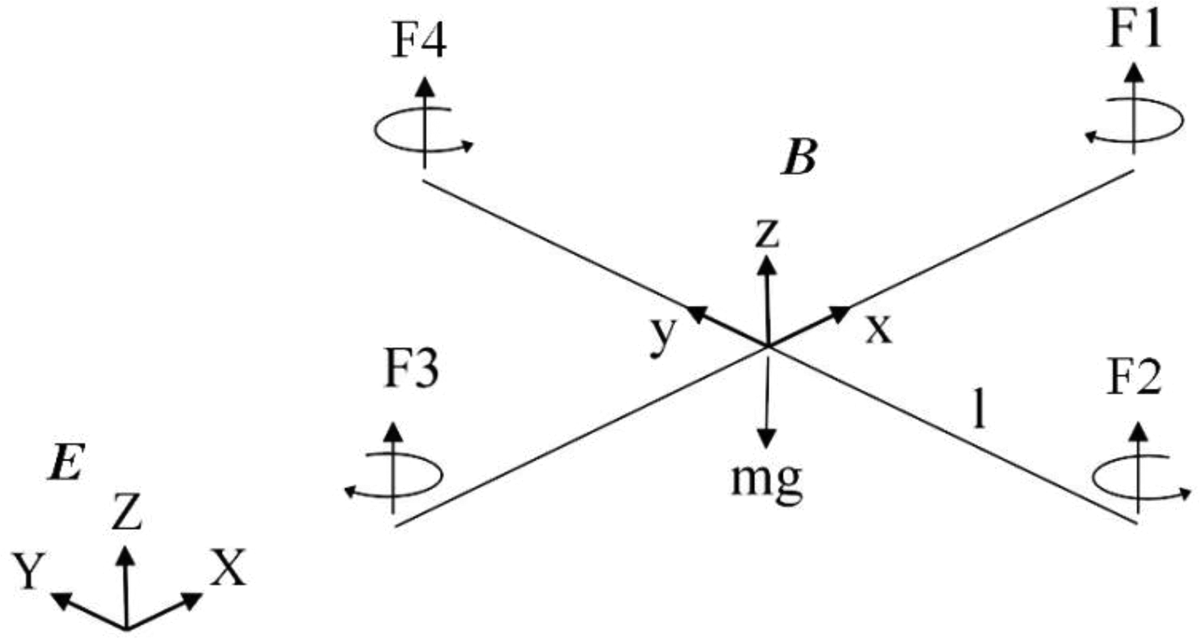
Quadcopter configuration, inertial frame E, and body frame B.
The first three equations of expression (1) describe the linear velocity vector, and the next three equations describe the angular velocity vector.
The relation among force, moment, and velocity of the rotor is described as follows 23

Equation (2) represents the system’s input variables of movement; Ω
i
denotes the speed of the propeller i;
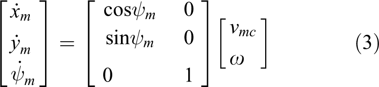
Kinematic equation
Let Rmc denotes the radius of the quadcopter (including propellers), and

Geometry of the quadcopter and an obstacle.
Collision-avoidance algorithm
Fundamental definitions
This section presents the definitions of important parameters of the quadcopter for laying the foundation of the proposed collision-avoidance algorithm. In order to be easy to compute and design a controller, the obstacle is considered as a circumsphere of real obstacle shape. These definitions are based on the geometry, as shown in Figure 2.
Definition 1: Boundary sphere of obstacle
The radius of boundary sphere of an obstacle is defined as follows

where Rob denotes the radius of the obstacle and
Definition 2: Obstacle detection
The quadcopter detects an obstacle when the relative distance Dt satisfies the following relation

where
Definition 3: Collision
The collision of the quadcopter with an obstacle occurs when the relative distance Dt satisfies the following relation

Definition 4: Collision detection and avoidance direction
Let β+ and β−
Collision detection: Collision will occur in the future if the velocity vector vmc of quadcopter is inside the collision cone NMP or the heading angle ψm satisfies the following relation

Avoidance direction. The quadcopter has two options to change the direction to avoid collision based on the heading angle. Let α denote collision detection angle and option 1: option 2:
Definition 5: Completion of collision avoidance
The collision avoidance is successfully completed if the projection of vector

where σ is scalar.

Completion of collision avoidance.
According to equation (8), if
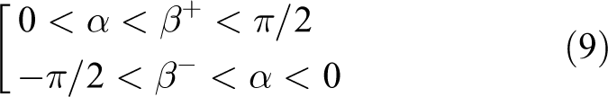
Definition 6: Collision algorithm activation
Let

Expressions (9) and (10) are the conditions to activate the collision-avoidance algorithm.
Controller design
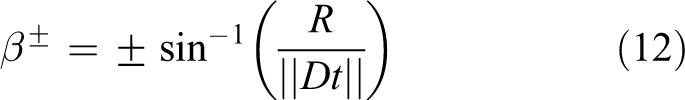
In this section, the guidance and velocity control laws are designed to avoid obstacles. The objective is to design a controller such that the collision detection angle α tracks the angle β± until

From geometry constraints, β± and α are computed as follows
The relative distance ‖Dt‖ is computed as follows

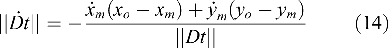
The derivative of ‖Dt‖ is computed as follows
From equation (12), the derivative of β+ and β− iscomputed as follows

Substituting equations (3) and (14) into equation (15), we obtain

The collision detection angle α is obtained as follows

where

From equations (17) and (18), the derivative of α is computed as follows
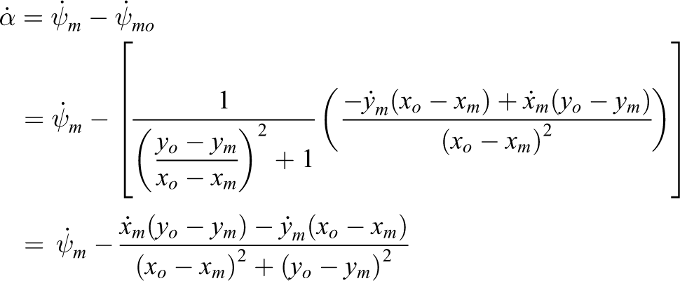

Substituting equation (3) into equation (19), we obtain


Substituting equations (11), (16), (17), and (20) into equation (21), we obtain
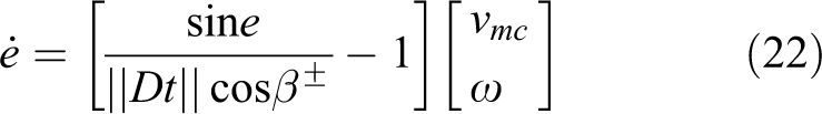
(Equation (22) is proved in Appendix 1.)
Consider that the candidate Lyapunov function and its derivative are given as follows


A method to achieve a negative value of

where k1 and k2 are positive values.
Controller gain turning
We assume that the heading angle of the quadcopter satisfies option 1 in definition 4. Let

Let
According to definition 1

where
From equation (27), βmin is obtained as follows

Let
From equation (27), emax is obtained as follows

According to equations (25) and (26)

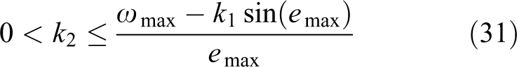
Expression (31) is satisfied if
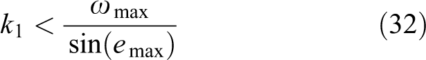
The controller gains k1 and k2 are obtained from equations (30) to (32).
In option 2 (definition 4), the controller gains k1 and k2 can also be determined by the same method as for option 1. Expressions (30) to (32) are also effective for option 2.
Collision avoidance with multiple obstacles
In this section, the collision-avoidance algorithm is extended for multiple obstacles. To avoid collisions with multiple obstacles, a new avoidance direction is recalculated based on the number of obstacles and geometry constraints. Let us assume that the quadcopter can detect all obstacles within the range of sensor. Typical cases of multiple obstacles are shown in Figure 4(a) and (b). Two obstacles are considered to define the collision zone; the relative position between the quadcopter and multiple obstacles is considered as follows.

(a) Relation between quadcopter and two obstacles O1 and O2 when collision will occur. (b) Relation between quadcopter and two obstacles O1 and O2 when collision will not occur.
In Figure 4(a), the collision may occur between the quadcopter and two obstacles (obstacles O1 and O2) because the velocity of the quadcopter vmc is in the collision zone of obstacle O1

The collision zone is defined as follows in Figure 4(a)

Collision may occur if the relative position of the quadcopter and multiple obstacles satisfies both expressions (33) and (34).
Conversely, collision will not occur between the quadcopter and two obstacles O1 and O2 in Figure 4(b) because the relative position of the quadcopter and two obstacles does not satisfy expression (33). In this case, the velocity vmc is not in the collision zone of obstacle O1 or O2, and collision-avoidance action is not required. If the velocity vmc is in the collision zone of obstacle O1 or O2, this case becomes the single-obstacle problem.
In Figure 4(a) and (b), two obstacles are considered. However, additional obstacles can be included with the same method. The proposed algorithm is extended to n obstacles. Again, we assume that the quadcopter is able to detect n obstacles within the range of the sensor; the relative position between two consecutive obstacles and quadcopter satisfies expression (33); and vector vmc is in the zone of collision

Relation between quadcopter and multiple obstacles: extended method.
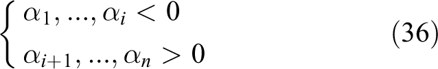
The collision detection angles of n obstacles are calculated as follows

where
From Figure 5, it is easy to recognize that the quadcopter has two directions to avoid obstacles: The first direction is to turn left of the obstacle O1 and the second direction is to turn right of the obstacle On. The collision-avoidance strategy is divided into three cases: case 1: Let case 2: Let case 3
Let
Therefore, the current velocity vmc is in
From expression (36), the quadcopter can choose from two directions to avoid the series of obstacles: left or right.
The avoidance direction is determined as follows


The tracking error angles of two avoidance directions are obtained as follows


From equations (39) and (40),
If

and α tracks
If

and α tracks
The proposed controller at equation (25) based on the Lyapunov stability is also effective in this case (The proposed controller at equation (25) based on the Lyapunov stability is also effective in case 3. It is proved in Appendix 2.).
Target position approach
This section introduces the algorithm to steer the quadcopter to the target position after the completion of collision avoidance.
In option 1, let
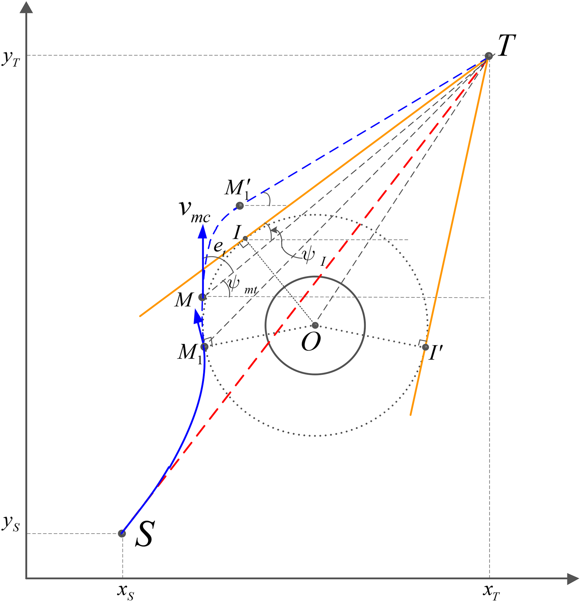
The path of quadcopter to reach the target position after obstacle-avoidance completion.
Area 1
The current position of the quadcopter

where


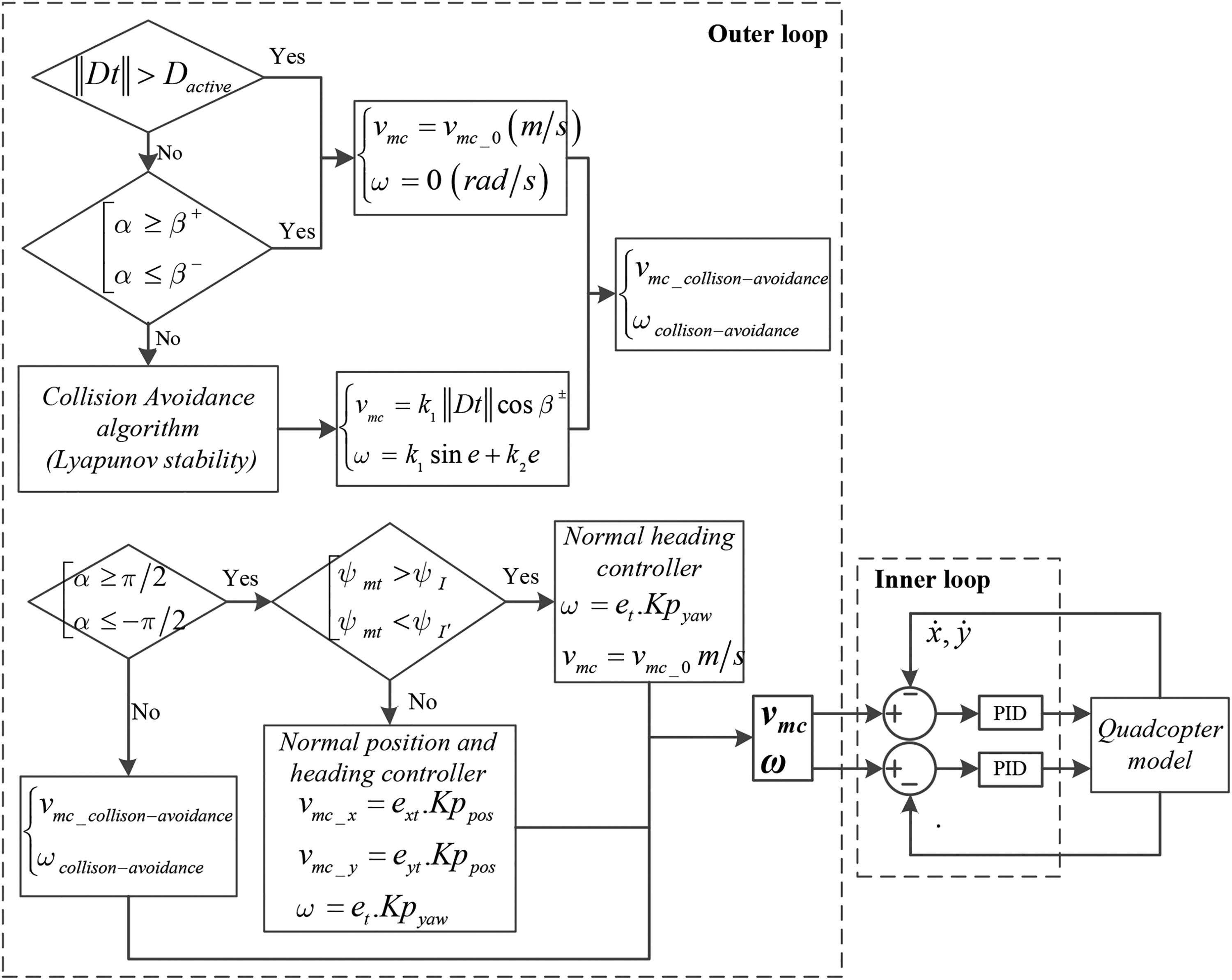
General block diagram of proposed algorithm.
Area 2
Once the position of the quadcopter M is outside the angle


where
When the quadcopter closely approaches target point


The method to reach the target point in option 2 (definition 4) is identical to that in option 1.
Simulation results and discussion
Simulation conditions
Numerical simulations were conducted to test the performance of the proposed method. Several conditions and assumptions were considered for the simulations. First, the case of a stationary obstacle is considered. The position and velocity of the quadcopter are determined from the embedded global positioning system (GPS)/inertial navigation system (INS) systems. The obstacles are detected by a light detection and ranging (LiDAR) or vision sensor system.
Second, the simulation assumed that the quadcopter is in flight at a constant altitude h = 10 m, with the start position S(1, 1) and a constant velocity of 2 m/s. An obstacle exists at position
Numerical parameters and initial values for simulation.

Simulation results
In this section, the results of the simulation are presented to demonstrate the effectiveness of the proposed collision-avoidance algorithm.
Single obstacle
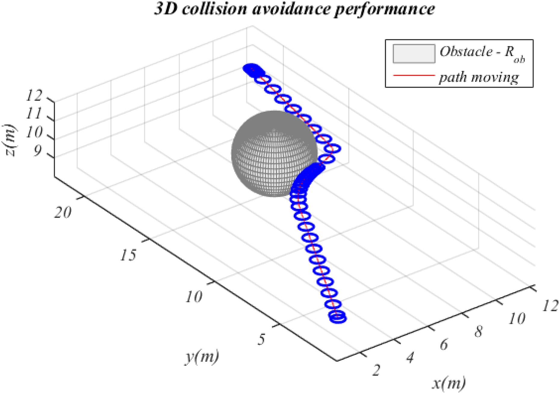
The first simulation was conducted for option 1 in definition 4. This simulation was performed with the target position of the quadcopter set to T(11, 23). Hence, the velocity vmc is in the left-half collision cone NMO (Figure 2). The simulation results are shown in Figures 8 to 15. All the figures are divided into three areas by the time of collision-avoidance algorithm activation and the time at which α ≥ β+ (as shown in Figures 10 and 12).
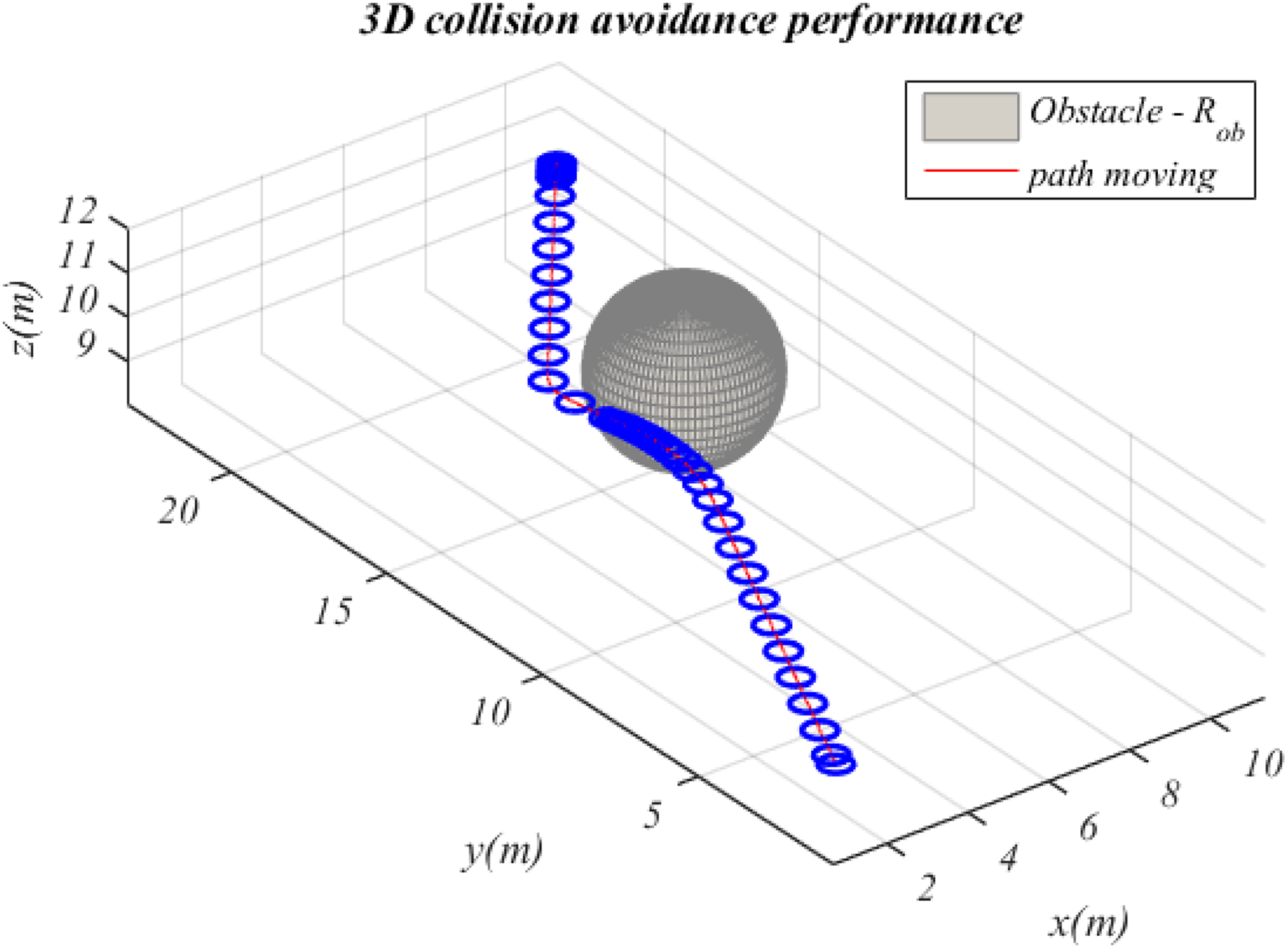
Path performance in three dimensions with target position

Path performance in two dimensions with target position
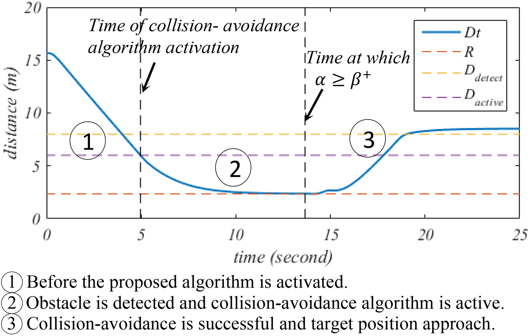
Relative distance between the quadcopter and obstacle with target position
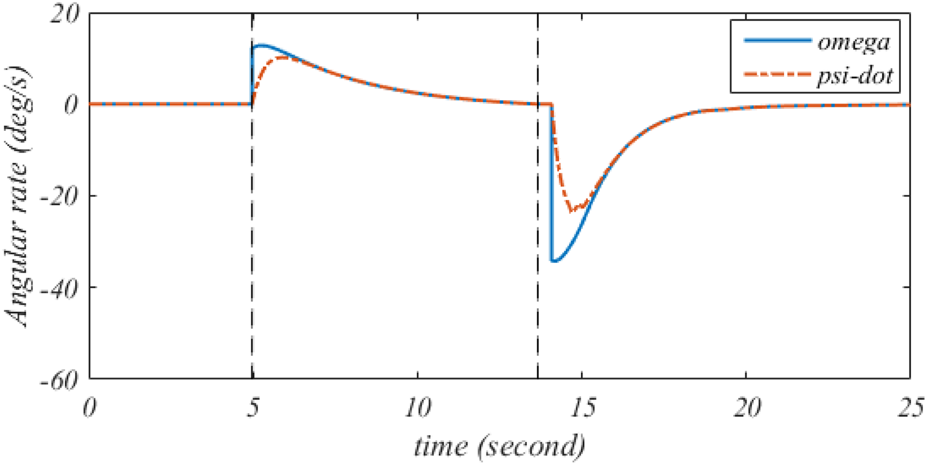
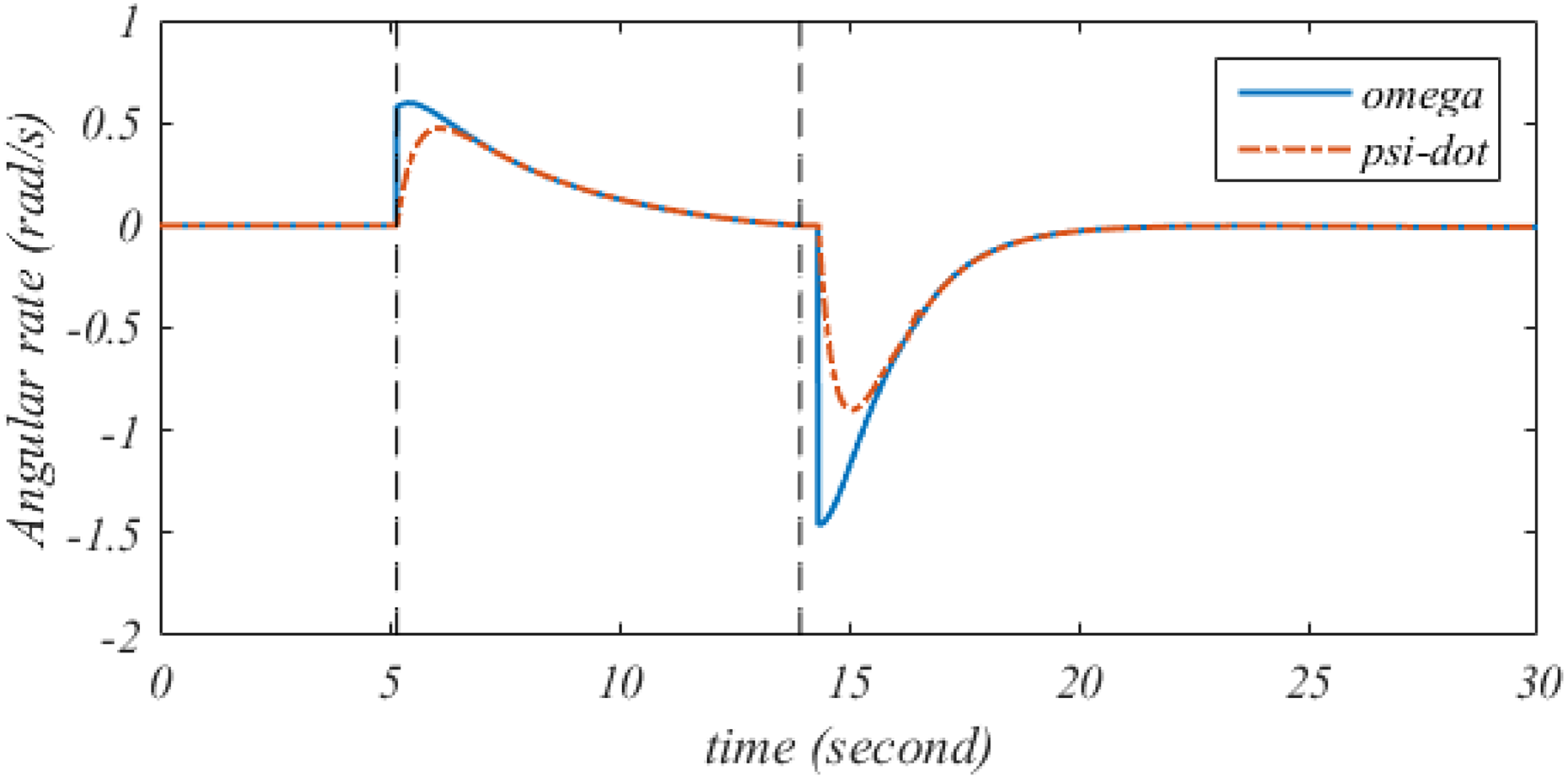
Heading angular rate performance of the quadcopter with target position
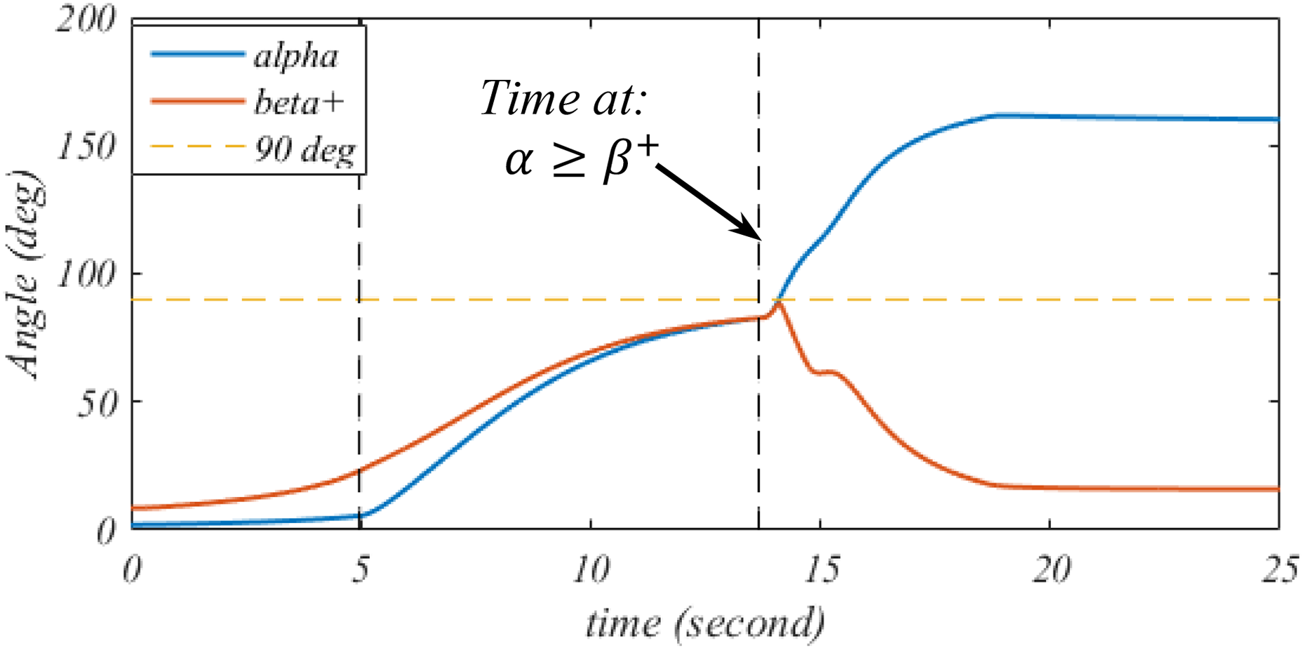
Angle α tracking β+ with target position

Tracking error e with target position

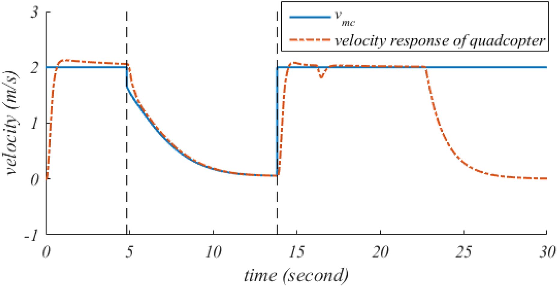
Velocity performance of the quadcopter with target position

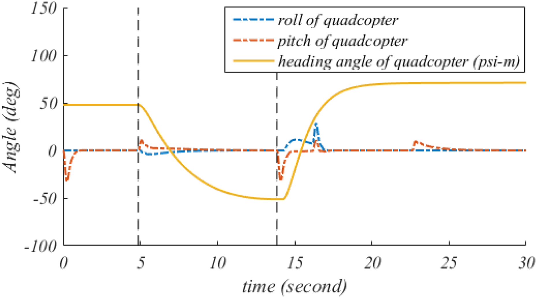
Attitude angles and heading angle of the quadcopter with target position
In area 1, the collision-avoidance algorithm is not activated because the relative distance is greater than active distance
At time t = 3.9 s, the obstacle is detected
As shown in Figure 14 (in area 2), the velocity gradually decreases as the quadcopter comes closer to the obstacle. In the meantime, the heading angular rate ω starts to increase and then gradually decreases when the quadcopter approaches the obstacle (Figure 11). Hence, α tracks β+ (Figure 12), and tracking error converges to zero (Figure 13). The heading angle ψm gradually increases to turn the quadcopter left for collision avoidance, as shown in Figures 8, 9, and 15. During this process, the relative distance is always greater than the boundary radius
Area 3 begins at time
At time t = 14.07 s, α ≥ 90° ≥ β+ (Figure 12), the collision avoidance is successful, and the target position approach algorithm begins to work. Therefore, the magnitude of the heading angular rate ω starts to increase (toward the negative direction) to drive the quadcopter toward the target position with a constant velocity of 2 m/s (Figures 11 and 14). Once the quadcopter is close to the target position, the velocity decreases so that the quadcopter stops at the destination. In addition, the movement trajectory of the quadcopter for collision avoidance is shown in 3D and two-dimensional (2D) in Figures 8 and 9, respectively.
The second simulation was performed for option 2 in definition 4, with the target position of the quadcopter set to T(12, 22). Hence, the velocity vmc is in the right-half collision cone
Path performance in three dimensions with target position T(12, 22).

Path performance in two dimensions with target position T(12, 22).

Relative distance between the quadcopter and obstacle with target position T(12, 22).

Heading angular rate performance of the quadcopter with target position T(12, 22).

Angle α tracking β− with target position T(12, 22).

Tracking error e with target position T(12, 22).

Velocity performance of the quadcopter with target position T(12, 22).

Attitude angles and heading angle of the quadcopter with target position T(12, 22).
At time t = 4.9 s, the relative distance
At time t = 13.67 s, α becomes less than β− (Figure 20). Thus, the velocity vector of the quadcopter is outside the collision zone. Therefore, the algorithm to avoid obstacles stops working. However, α and β− are continuously approaching −90°. From this point onward, there is no possibility of collision, and the velocity of the quadcopter starts to increase to a constant velocity of 2 m/s (Figure 22). The angular rate ω is zero (Figure 19), and heading angle ψm becomes a constant value (Figure 23).
At time
Multiple obstacles
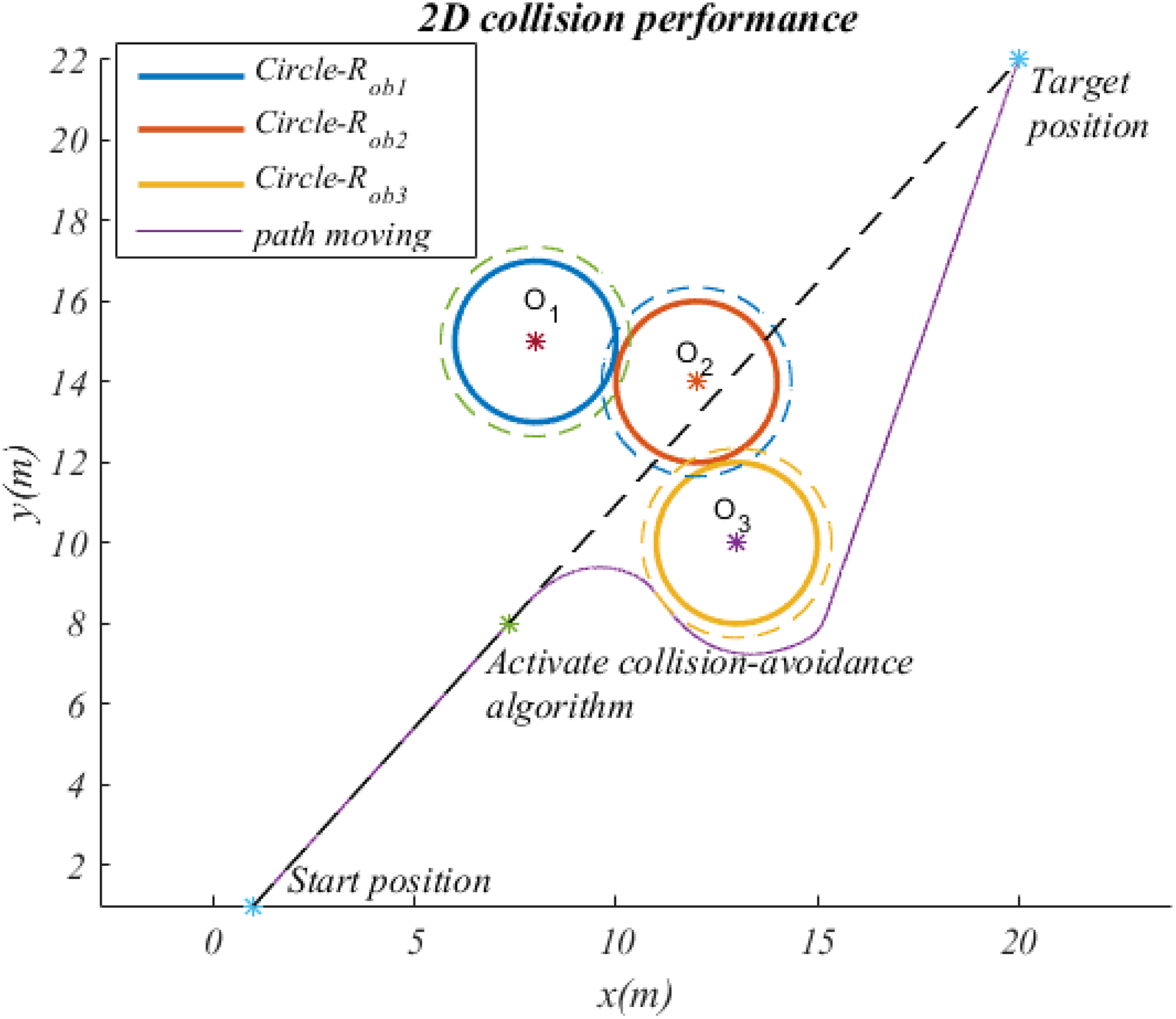
The last simulation was performed with multiple obstacles. Three obstacles were considered in this case, and their positions are O1(8, 15), O2(12, 14), and O3(13, 10). The other conditions are listed in Table 1. Simulations were performed with the target positions of the quadcopter set to T(18, 24) and T(20, 22).
For T(18, 24)
The quadcopter moves toward the multiple obstacles

Path performance in three dimensions with multiple obstacles and

Path performance in two dimensions with multiple obstacles and
As shown in Figure 26, once

Relative distance between the quadcopter and multiple obstacles with T(18, 24).

Attitude and heading angle of the quadcopter with multiple obstacles and T(18, 24).

Angle α = α1 tracking

Tracking error e with multiple obstacles and T(18, 24).

Velocity performance of the quadcopter with T(18, 24).
Heading angular rate performance of the quadcopter with T(18, 24).
For T(20, 22)
The next simulation was conducted with the target position of the quadcopter set to T(20, 22); the other conditions are listed in Table 1. The results of the simulation are shown in Figures 32 to 39. In this case, the velocity vmc is in the collision cone

Path performance in three dimensions with multiple obstacles and T(20, 22).
Path performance in two dimensions with multiple obstacles and T(20, 22).

Relative distance between the quadcopter and multiple obstacles with T(20, 22).
Attitude angles and heading angle of the quadcopter with multiple obstacles and T(20, 22).

Angle α = α3 tracking

Tracking error e with multiple obstacles and T(20, 22).
Velocity performance of the quadcopter with T(20, 22).

Heading angular rate performance of the quadcopter with T(20, 22).
The simulation results demonstrate the effectiveness of proposed method. The advantages of this algorithm are simplicity, low computational requirements, and ability to find the shortest path to avoid obstacles and reach the target position after completion of collision avoidance. Both heading angular rate and velocity of quadcopter are considered simultaneously to ensure that collisions do not occur when the vehicle travels at high speed. This method overcomes the disadvantages of previous studies that only concern guidance law. 9,13,16 This algorithm is also effective to multiple obstacles. Finally, the proposed simple method can be used to avoid collisions for quadcopter or multicopter in a static environment.
Conclusions
In this article, a new approach to control quadcopters to avoid obstacles was introduced. This method can be applied to avoid single or multiple obstacles. To design the guidance and velocity control laws, a tracking error was defined to determine the avoidance direction. The controllers are obtained from Lyapunov stability. Furthermore, the controller gain can be found easily with the presented turning method. In addition, a target position approach method to steer the quadcopter to reach the destination was presented.
Numerical simulations for different scenarios were performed, and the results demonstrated the good performance of the proposed method. However, the study did not consider collision avoidance for moving objects and external disturbances. Therefore, the extension of this method to dynamic environments and external disturbances will be studied in the future.
Footnotes
Declaration of conflicting interests
The author(s) declared no potential conflicts of interest with respect to the research, authorship, and/or publication of this article.
Funding
The author(s) disclosed receipt of the following financial support for the research, authorship, and/or publication of this article: This work was supported by the Korea Institute for Advancement of Technology (KIAT) grant funded by the Korean government (MOTIE: Ministry of Trade, Industry, and Energy) (no. N0002431).