
Abstract
To make a biped robot walk stably at various speeds, a novel switch control approach is proposed to make the gaits switch smoothly between different walking speeds. The switch controller is designed based on the Lyapunov stability theory and the sufficient condition is given to make the closed-loop system stable. This controller can allow the robot to reach the stable gaits corresponding to the various speeds and improve the robustness of switch process. Potential energy compensation control has been studied in the dynamic model of a passive dynamic walking robot with knees. The functional relationship between the initial states and the walking speed is obtained. Numerical simulations are provided to verify the effectiveness of the control strategy.
1. Introduction
The idea of passive dynamic walking was pioneered by McGeer more than a decade ago[1]. A stable walking motion that does not require any external energy source except gravity effect is called passive dynamic walking.
McGeer designed several unpowered biped robot prototypes and studied their gravity-induced passive walking down a shallow slope [2]. He demonstrated that the machines can attain a stable natural periodic gait and the passive walking has high energy efficiency. Since then, passive walking has been widely studied by several researchers [3, 4, 5]. However, the passive gaits exist for only shallow slopes and are sensitive to slope magnitude and initial conditions [6, 7, 8]. Thus, the active feedback control laws to yield a stable walking motion have been investigated by several researchers. These control laws were based on the passivity property of the biped robot. Spong has used the potential-shaping control to make the biped robot walk on any slope [9, 10]. Furthermore, the total energy-shaping control for the passive biped robot has been proposed to enlarge the basin of attraction and increase the rate of convergence [11]. A virtual gravity field is introduced to act as a driving force, which realizes the virtual passive walking on level ground [12]. The reinforcement learning-based method was used to control the robot to walk on an uneven floor [13, 14]. Some approaches to producing periodic walking motions while keeping a low energy control have been designed [15–17]. The emphasis in the literature is mainly on how to enlarge the basin of attraction, increase the rate of convergence and improve the robustness to disturbances, therefore a wide range of behaviours has not been investigated.
In this paper, we are primarily interested in proposing a feedback control method which can make the gaits switch smoothly between different walking speeds. Then the biped robot can walk steadily at the various speeds and the range of walking speeds can be expanded. Russell and Granata have designed the virtual slope control algorithm to control the average walking velocity by modifying the controller coefficients [18]. Yamakita and Asano have combined a virtual passive walk with passive velocity field control (PVFC) to regulate the walking speed effectively [19]. In addition, Grizzle has designed a switching and event-based PI feedback control to regulate the average walking rate to a continuum of values [20, 21]. Holm and Spong have discussed kinetic energy-shaping as a means of controlling the speed while adjusting step length [22]. In addition, a time-scaling control law has also been proposed to regulate the walking speed and the transition between limit cycles in a single step has been achieved for a biped robot [23, 24]. Other regulation methods which can lead to stable walking at various speeds have also been introduced in [25–27]. Methods in the previous research are effective in regulating the speeds, yet most of them are designed for a biped robot without knees or limitations on the range of walking speeds achievable are encountered. Therefore, the focus of this paper is to design a speed switch control for a biped robot with knees to regulate the speeds within a large range.
The paper is organized as follows: Section 2 presents a dynamic model of the biped robot with knees. Switch control between different speeds for the biped robot with knees is presented in Section 3. In this section, we describe the principle and structure of the switch controller. The stability analysis is also studied in Section 3. Section 4 is the numerical simulations that verify the effectiveness of the methods proposed in this paper. Finally, Section 5 is devoted to conclusions and future work.
2. Dynamic Model of a 2-D Biped Robot with Knees
Figure 1 shows a model of a 2-D biped robot with knees. This robot has no torso and consists of two legs without feet. Each leg has a thigh and a shank connected at the knee joint that has a knee stopper. With the knee stopper, the angle of the knee rotation is restricted like the human knee. Masses concentrate at three points: hip, thigh and shank. Table 1 lists the symbols and physical meanings of the configuration parameters in the model of the biped robot with knees. The walking cycle is divided into four stages, as shown in Figure 2[28]:
f and the average walking speeds


Model of the biped robot with knees.

Four stages in one step cycle for the biped robot with knees.
Stage I: The stance leg straightens out and the knee is locked, just like a single link. Meanwhile the swing leg with unlock knee comes forward, just like two links connected by a frictionless joint. This stage is called the unlocked swing stage.
Stage II: When the thigh and the shank of the swing leg have the same angle, the knee of the swing leg is locked. Then the swing leg straightens out and the knee-strike occurs. We make the standard assumption that the knee-strike is perfectly inelastic.
Stage III: The knee joint of the swing leg is locked after the knee-strike. Then, the swing leg keeps straight after the knee-strike. Thus, this stage is just like the swing phase of the compass-like robot. This stage is called the locked swing stage.
Stage IV: The swing leg impacts with the ground. This stage is called the heel-strike. The heel-strike is assumed to be inelastic and there is no slipping at the stance leg ground contact. Transfer of support between the swing leg and the stance leg is instantaneous.
2.1 Equation of the Unlocked Swing Stage
The dynamic equation of the unlocked swing stage obtained by the Euler-Lagrange approach is given as

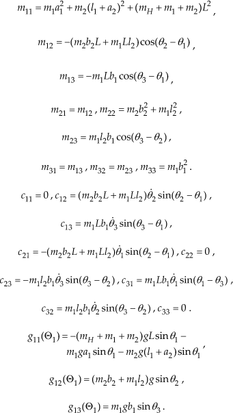
whereM 1(Θ1) is the 3 × 3 inertia matrix, 
where
2.2 Knee-Strike Equation
In Stage II, the knee-strike results in an instantaneous change of the velocities of the joints, but the configuration of the biped robot remains invariant. Then the pre-impact and the post-impact configurations of the robot can be expressed as Θ1+ = Θ1−, where the index “-” means before the knee-strike and the index “+” means after the knee-strike. Based on the conservation of angular momentum, we obtain the knee-strike equation as follows:

The matrix H1(Θ1−) = Q1·Q1−,
where

2.3 Equation of the Locked Swing Stage
In Stage III, the knee-joint is locked and the swing leg keeps straight after the knee-strike. The model in this stage is just like the compass-like robot. Thus, the swing equation of the compass-like robot can be used to describe the locked swing stage. The equation of the locked swing stage is

where M2(Θ2) is the terms and g2(Θ2) is the gravity terms. 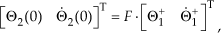
where 
The matrices 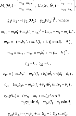
2.4 Heel-Strike Equation
Since the robot with knees can be regarded as the compass-like robot after the knee-strike, the heel-strike transition equation of the compass-like robot can be applied directly to the biped robot with knees. The heel-strike equation is listed as follows:
where the index “−” means before the heel-strike and the index “+” means after the heel-strike. H2(Θ2) = (P2+)−1 P2−, where

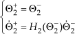
After the heel-strike, the previous swing leg becomes the new stance leg and the previous stance leg becomes the new swing leg. Therefore, the initial state of Stage I satisfies
where 
3. Switch Control between Different Walking Speeds
In this paper, the walking speed is defined as the average walking speed. Thus, the walking speed v̄ can be easily computed as
In this section, we introduce the theory of the potential energy compensation control first. Then, the results of the potential energy compensation control are extended to the biped robot with knees to solve the stable walking at the ideal speed. Finally, we propose a switch control between different speeds to realize stable walking at the various speeds.
3.1 Potential Energy Compensation Control for the Biped Robot with Knees
Several researchers have shown that regulations of walking speeds may be accomplished via potential energy-shaping control. From a given passive limit cycle, we can obtain the active limit cycle with any desired speed. These results are given by a theorem proved in [29]. Contents of the theorem are given as follows:
where g(θ) is gravity term of the robot, there is a stable limit cycle with speed v̄e and the initial state is
We suppose that the biped robot with knees has a passive walking gait at speed v̄0. Motivated by theorem 1, we propose the potential energy compensation control law for the biped robot with knees. The controller in the unlocked swing stage is designed as

Then, the dynamic equation of the unlocked swing stage is transformed to be

Moreover, the torque vector of the locked swing stage is designed as
The equation of the locked swing stage is transformed to be

With control laws (6) and (8), the biped robot with knees can walk stably at the desired speed v̄e.
Consequently, the numerical simulations are performed to demonstrate the effectiveness of the potential energy compensation controllers for the biped robot with knees. The values of parameters used in simulation are mH=1[kg], m1=0.1[kg], m2=1[kg], a1=0.375[m], L=1[m], b1=0.125[m], a2=0.175[m], b2=0.325[m], Θ=0.0524[radian]. For u = 0, the biped robot with knees has a passive limit cycle with speed 0.9456m/s. Initial states of the passive dynamic walking are

Thus, the initial states in the simulation are set to be

We use MATLAB to carry out the simulations. Table 2 lists the speed values for the different limit cycles. Both of them illustrate that the potential energy compensation control for the biped robot with knees can drive the robot to walk at the desired speed. Figure 3 and Figure 4 show the curves of the kinetic energy and the potential energy for the different f in a single cycle step. It is demonstrated that the potential energy and the kinetic energy all increase with accelerating the speeds. The bigger f is, the greater the compensational potential energy. Then, there is more energy to compensate the lost energy during the knee-strike and heel-strike. Thus, the kinetic energy can be increased to accelerate the walking speed for the biped robot with knees.
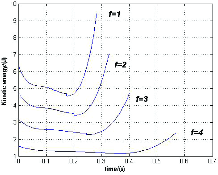
Kinetic energy in a single step

Potential energy in a single step
3.2 Design of the Speed Switch Controller
The potential energy compensation control developed above can make the biped robot with knees walk at the desired speed. If we design a switch law from one desired speed to another desired speed, the biped robot with knees will walk at the various speeds with a large range of regulating speeds. Based on the Lyapunov stability theory and the feedback linearization theory, a speed switch controller is designed in this section.
Since it is easy to detect the heel-strike and obtain the state just after the heel-strike, the state 
the torque vector in Eq. (10) is designed as

Meanwhile, the equation of the locked swing stage in the ith step of the speed switching process is

We design the torque vector in Eq. (12) to be as

where
Let e1 = Θ1 −Θ
d
1, e2 = Θ2 − Θ
d
2. The closed-loop system in the ith step of the speed switching process is

Let tsi be the starting time of the ith step in the speed switching process and tki be the time instant at which the knee-strike happens in the ith step of the speed switching process. Meanwhile, let thi be the time instant at which heel-strike happens in the ith step of the speed switching process and thi also be the starting time of the (i + 1) th step in the speed switching process.
In the ith step of the speed switching process, the equations of the knee-strike and heel-strike are respectively


Then, the states just before and after the knee-strike satisfy

The states just before and after the heel-strike satisfy

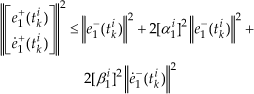
If we select the appropriate gains K1 and K2, the errors exponentially decrease in the speed switching process. Since H1(·) and H2(·) are differentiable everywhere and locally Lipschitz, there are the constants αi1 > 0 and αi2 > 0, such that

Let βi1 = ‖H1(Θ1−(tki))‖ and βi2 = ‖H2(Θ2−(thi))‖. From Eq. (17) and Eq. (18), we have

Since

and 
thus
Denote ωi1 = max{1 + 2(αi1)2, 2(βi1)2},
where ωi1 depends on the states just before the knee-strikes in the ith step of the speed switching process and the walking at speed v̄2.
From Eq. (19), we have

Similarly, a constant ωi2 > 0 exists such that

where ωi2 depends on the states just before the heel-strikes in the ith step of the speed switching process and the walking at speed v̄2.
In the ith step, Eq. (14) can be transformed as

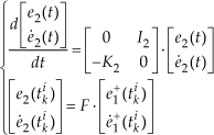
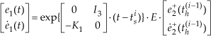
where I3 is the third-order identity matrix and I2 is the second-order identity matrix. Solutions of Eq. (22) and Eq. (23) can be represented as respectively

Denote

When the gains K1 and K2 satisfy the following conditions, the biped robot with knees can realize the smooth switch between the different speeds.
Then

Proof: We assume that V1−(tk(i+1)) represents as the error values just before the knee-strike in the (i+1) step, namely

Since

then
From (20), (21) and (25), we have

Since V1−(tk(i−1) ≤ V1−(tki) and V1−(tki) is nonnegative, we have

From Eq. (27), we have

That is to say that the state just before the knee-strike in the each step is asymptotically converged to the state just before the knee-strike of the walking at desired speed v̄2. Also from (20), we have 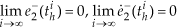
Eq. (29) illustrates that the state just before the heel-strike eventually converges to the state just before the heel-strike of the walking at speed v̄2. Hence the robot can walk at speed v̄2. Gaits of walking at speed v̄1 finally switch to the gaits of walking at speed v̄2, namely,
4. Simulation Results
In this section, we describe an example of a biped robot with knees walking at the various speeds using our proposed approach. Adjustment of speeds is done from 0.8446m/s to 1.4628m/s. The model and parameters used in these simulations are the same as the ones in section 3.1. Figure 5 describes the changes of speeds. The biped robot walks at the speed of 0.8446m/s for ten steps, then regulates the speed to 1.4628m/s, and finally walks at the speed of 1.4628m/s for ten steps. Figure 6 is the angular velocity trajectories of the hip joint in this process. Figure 7 shows the energy changing results with regulating the speeds. Figure 8 presents the input torques with changing the speeds. Comparing with the desired speed, the results show that the speed from 0.8446m/s switches to 1.4628m/s successfully and speed switching process is smooth and natural.
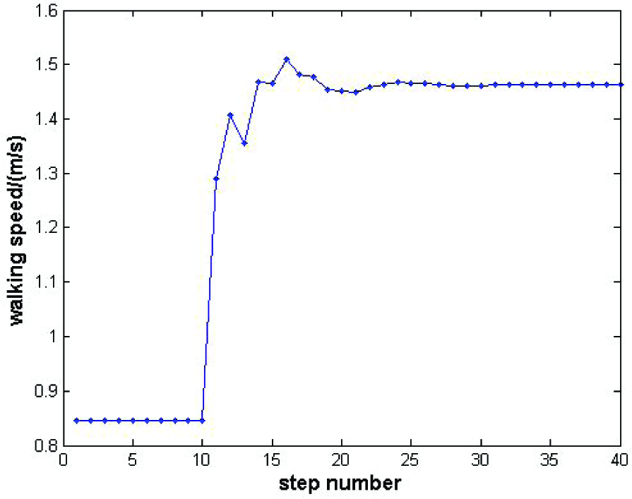
Walking speeds with changing the step numbers

The angular velocity trajectories of the hip joint with regulating the speeds

The kinetic energy and the potential energy with regulating the speeds

Input torques in the simulation
In order to test the robustness of the speed switching process, 10Nm impulsive torque is imposed on the hip joint in the fourth step of the speed switching process. Figure 9 shows that the bipedal walking can also be regulated to the desired speed. Then, the numerical simulation results demonstrate that the speed switch controller can not only make the robot walk at the various speeds, it can also make sure that the switching process has a favourable robustness.
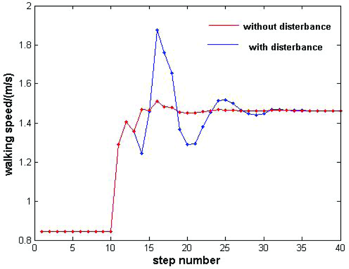
Comparison curve of the walking speeds when an impulsive disturbance is imposed on the hip joint
5. Conclusions
In order to make the biped robot with knees walk at the various speeds, a control algorithm named the speed switch control is proposed in this paper. The speed switch control ensures smooth switching between the different gait speeds and also expands the range of regulating the speeds achievable. Based on the theory of Lyapunov stability, the sufficient condition is given, which ensures the closed-loop system is stable. In addition, the stability analysis has been done. Finally the effectiveness of the control algorithm is verified with the numerical simulations. It is shown that the speed switch controller can not only realize smooth switching between different speeds, it also has strong robustness.
How to use the speed switch control in a biped robot prototype is the subject for future research.
Footnotes
6. Acknowledgments
This work is supported by National High Technology Research and Development Programme of China (863 Program), grant no. 2006AA04Z251; National Natural Science Foundation of China, grant no. 60974067.