
Abstract
This paper presents a kinematic analysis and simulation of a hybrid structure applied to the new design cable-suspended feed structure (CSFS) for the next generation of large spherical radio telescopes. First, considering the requirement that feeds should be tilted from 40° to 60° and that the tracking precision in steady state is 4mm, a novel design of the feed supporting structure including a cable-cabin structure, an AB axis structure and a Stewart platform is performed. Next, kinematic analysis and the simulation of the CSFS are done. Simulations have been developed in combination with the 50m CSFS model, which demonstrate the effectiveness and feasibility of the proposed three-level cable-suspended feed system.
1. Introduction
The new-generation large radio telescope (LT) will provide treasures to astronomers as well as bringing prosperity to other areas of research – for instance, space weather study, deep space exploration and national security. The LT has been studied by Canadian scientists (led by the National Research Council of Canada and supported by university and industry collaborators), German scientists, American scientists, Indian scientists [1] and Chinese scientists [2]. Every LT project has its own feature. Here, a Chinese LT is brought forth.
Chinese engineers began designing a five-hundred-meter aperture spherical radio telescope (FAST) in 1994, which is a centimetre-to-metre wave radio telescope for the investigation of cosmic phenomena [3]. Figure 1 is an artist's impression of the complete 500m diameter FAST installation from National Astronomical Observatories, the Chinese academy of sciences (NAOC). The FAST consists of two central components. The first is a 500m diameter parabolic reflector, composed of an array of around 2,000 individual active reflector panels supported on the ground [4]. The second component is a light-weight feed cabin which is driven by cables, consisting of a cabin tied by multiple long cables and a stable Stewart platform fixed on the cabin's bottom plate. It is an original cable-suspended feed structure (CSFS), called a two-level feed structure.

500m Concept Model
A sketch of FAST is shown in Figure 2. Suppose that the curvature radius of the reflector is R with a centre O'. According to the working requirement, the cabin is moved on a spherical shell with the radius of 0.533R. OXYZ is the global coordinate frame. Axis Z1 of the local coordinate frame O1X1Y1Z1 is coincident with the symmetry axis of the cabin, but the cabin can make a relative rotation round axis Z1 and θ is the rotation angle. During operation, the axis Z1 should always pass through the centre O' and the axis Y1 should always intersect with the axis Z. As such, the axis X1 is always orthogonal to Z; α, γ and θ show the orientation of the cabin; α is the angle between the planes O1Y1Z1 and OXZ; γ is the angle between the axes Z and Z1. The maximum of γ is φ/2, as shown in Figure 2.

Sketch Map of FAST
As far as the CSFS is concerned, the requirement of orientation increased from 40° to 60° – that is, the angle <O1O'O at the edge of the workspace in Figure 2 was proposed by the international square kilometre array (SKA) committee in 2004. This brings forth a problem in that the original cable-suspended feed structure (CSFS) that we put forward – above – found it difficult to achieve the required pose. As we know, a six-cable system is not a fully constrained system for the position and orientation of the cabin platform, since in adding the cabin gravity it receives six degrees of freedom in a limited workspace. To achieve the orientation 60°, it increases the divergence among the cable tensions, which is not beneficial for the control and economizing of energy. In addition, there is also an effect on electronic performance because the receiving frequencies of the electromagnetic waves of the feed are required to cover a wider operation bandwidth 0.13 to 8.8 GHz [5]. Yao etc. [6] put forward a four cable structure. The cabin can perform a translational motion. It affects the workspace and the precision of the feed cable-suspended system. To meet these new needs, the CSFS is redesigned and a kinematic analysis and simulation of the CSFS are performed in this paper.
2. The New Cable-suspended Feed Structure
Based on an analysis of the original two-level feed structures, the new cable-suspended feed structure is described. A 50m scaled model (Figure 3) of the CSFS, built in Xidian University, is taken as an example. In this scheme, the six cable towers are not designed with the same heights – one group of cables is connected to the bottom circle of the feed cabin through the top of the three towers apart; the other cables are connected to a small circle on the top of the feed cabin (Figure 4) to eliminate the singularity [7]. In the following discussion, the cables connected to the bottom circle of the cabin are called the ‘lower cables’, while the tower on which the pulley is fixed and through which one lower cable is connected to the cabin is called the ‘lower cable tower’. As such, the upper cable and the upper cable tower are defined (Figure 3) in the same way. When the orientation of the feed cabin is increased from 40° to 60°, the cable force will increase dramatically in the original scheme. Considering the limitation of cable tension difference and all kinds of constraint conditions, we redesign the 50m scaled model of the CSFS as in Figure 5.

50m Scaled Model

Detailed view of the Cabin's design variables

The Three Levels Model (with and without the shell)
The new CSFS is a three-level system, as shown in Figure 5a. It consists of a shell (the grey part), a shell framework (the yellow parts), an AB framework (the green parts) and a Stewart platform. The shell and cables are removed for convenience so as to see the detailed inside structure, shown in Figure 5b. The cable-driven light-weight feed cabin (including the shell and the yellow structure) is the first level of the new CSFS. The AB axis structure (green part) is the second level, which is similar to a gyro and can rotate with an orientation of 40°. A stable Stewart platform is the third level. Accordingly, the cabin only needs to rotate by 20°. The AB axis structure is charged with 40° to the orientation angle of the CSFS. A Stewart platform is used for error compensation to meet the tracking error request, which is less than 4 mm when the CSFS reaches its workspace.
Based on the parameters of a 50m scaled model of the CSFS, we have already optimized the design variables of the towers (in Figure 3), the cabin (in Figure 4), the AB axis structure (in Figure 5) and the Stewart platform by virtue of the optimization strategy in [8][9]. To meet the requirements of an orientation increased to 60°, the optimal objective is to make the lower and upper cable tension difference as small as possible and to make the difference between the absolute value of torque A (denoted by MA) and that of torque B (denoted by MB) as small as possible, which is beneficial to the control and economizing of the energy.
The optimization problem of the towers and the cabin are briefly outlined here:

where h1, h2, …,h6 are the heights of the lower and upper cable towers as shown in Figure 3. The six design variables of the cabin are shown on the left of Figure 4: Rd and hd are, respectively, the radius and height of the bottom circle where the lower cables are connected to the cabin; Ru and hu are, respectively, the radius and the height of the top circle where the upper cables are connected to the cabin; rc 1 and rc 2 are the radius of the cross sections of the lower and upper cables. The projection of Bi at the bottom plane of the cabin is on the right of Figure 4. e˜ is the stagger angle between the adjacent lower cable point and the upper cable point, just as e˜ is the angle between the cable connection points B3 and point B4 in Figure 4.
Sketch Map of Cable AiBi and the Cable Force to the Cabin
3. Kinematic Analysis
In this section, the kinematics of the new cable-suspended feed structure system is studied. First, the inverse kinematic analysis of the cable-driven feed cabin is elaborated in detail and then the kinematics of the rigid AB axis structure and the Stewart platform are analysed. In order to verify the formulations, in Section 4 the simulation results for the computation of the inverse kinematics of the three-level manipulator are presented in detail.
3.1 Inverse Kinematics of the Cable-driven Feed Cabin
As for the inverse kinematic analysis of the cable-driven feed cabin, it is assumed that the position and orientation of the moving platform (xo1, yo1, zo1, α, γ, θ) T are given and that the problem is to find the length of the six cables, L = [L1, L2, L3, L4, L5, L6]T, where, α, γ and θ are shown in Figure 2 and depicted in the introduction.
Although the global coordinates of the origin O1 of the local coordinate frame O1X1Y1Z1 are given in the cable-driven feed cabin system, the five parameters (xo1,yo1,zo1,α, γ) can be confirmed except for θ. From the definition of θ (in the introduction, page 1), it can be seen that there are a group of solutions for the cable tensions corresponding to different θ for the given five parameters. As such, it allows us to choose the cable tension within a narrow scope of θ suitable for equilibrium. Due to the fact that the length of cable in space is related to its shape, mass, end force and the state of its locomotion, we should calculate the end force of the cable first.
3.1.1 The End Force of each Cable
The sketch map of a cable AiBi and the force on the cabin is presented in Figure 6. OXYZ is direction of the global coordinate frame. Bi is the position where the cable connects to the cabin. Hi Vi are the horizontal and vertical components of the cable tension Fi acting on the cabin in the cable plane Ai Bi, separately. βi is the angle between the cable Ai Bi vertical plane and the OXZ vertical plane in Figure 6.
The position vector of the cable end Bi in the global frame

where

In this study, the cable-driven feed cabin moves so slowly that it can be treated as being in a static state during its operation [10][11]. Therefore, a quasi-static analysis is made by substituting the static tension of a cable at a given position for the dynamic force of the cable at the same position. We get the following equilibrium equations of the cabin at a given position and orientation in the global coordinate frame:

where W is the weight of the cabin and its attachment; xd,yd are the cabin coordinates; xBi, yBi, zBi are absolute coordinates of the cable end Bi (denoted by the position vector
3.1.2 Cable Model
As the cable-driven feed cabin moves so slowly that it can be treated as being in a static state, the catenary curves are used to mathematically describe the cables. Consider a flexible cable stretched in a vertical plane with a length L, a horizontal span l, a vertical height h, a cross-sectional area A and a weight per unit length q0, as shown in Figure 6. The Zi-axis of the cable frame is in the negative direction of the global Z-axis. For simplicity, it is assumed that the gravitational acceleration is in the negative direction of the Z-axis.
From the moment equilibrium about cable end Ai of the cable, we have:

żi is the differentiation of zi with respect to xi that can be obtained from (6)[13]:

where the parameters ci1 and ci2 are the boundary conditions of the cable. This is the catenary equation which shows the relationship between the cable shape and the cable end force.
From (5) and (6), the vertical tension Vi can be expressed by the horizontal tension Hi. Substituting this expression into (4) gives the following matrix style equation:
According to the requirements of astronomical observation and for a predefined observation trajectory, five parameters (xo1,yo1,zo1,α,γ) T are given and θ can be chosen by an optimization to make the difference between the lower and upper cable tension as small as possible, which is beneficial to control and energy economization.
The optimization problem can be mathematically stated as:
According to the unique property of cables in that they can only carry loads in tension but not in compression [12], the restriction condition is Hi > 0. θ can be obtained by optimizing the cable force using (7).
From (6) and (4), the theoretical cable length Li can be expressed as:

When a predefined observation trajectory's five parameters (xo1, yo1, zo1, α, γ)
T
are given, the length of the six cables,
3.2 Inverse Kinematics of the AB Axis and the Stewart Platform
The AB axis structure and the Stewart platform are rigid body systems. Figure 7 presents the coordinates frame of the CSFS. According to the requirements of astronomical observation, the Z1 axis of the A axis local frame, O1X1Y1Z1 (denoted by red), is demanded to point the reference point O. The PZ axis of the B axis local frame, O1PXPYPZ (denoted by lilac), is demanded to pass through the reflector centre O', just like the orientations in Figure 7a. These two local frames have the same origin O1 and X axis. The local frame OPPXPYPZ is located in the centre of the static Stewart platform in Figure 7b and it has the same direction as the frame O1PXPYPZ. Oe is the centre of the moving platform of the Stewart and
Sketch map of the CSFS's coordinates
When the position and orientation of

where

where

We denote by


Accordingly, the rotation angle can be obtained as:

In which,
If there is no position or orientation error, the Stewart platform does not work and so
When there is an error between the real trajectory Oe_r and the theory trajectory Oe_t, the Stewart platform compensates the error. As illustrated in Figure 7, the loop closure equation for point Op is given by:

where
For the convenience of calculating the leg length of the Stewart platform, we express the error in the local frame OPPXPYPZ:

Then, according to the given parameters of the Stewart platform, substituting (16) into the inverse kinematic of the Stewart platform presented in [14] yields the corresponding leg length L =[Ls1,Ls2,Ls3,Ls4,Ls5,Ls6]T to compensate the error.
4. Simulation Results of the Kinematic Analysis
The inverse kinematic analysis of the three-level manipulator is given in Section 3 in detail. In order to verify the accuracy of the numerical solutions for a given trajectory for point Oe, the manipulator is required to operate according to the optimal trajectory, planning with minimal Stewart platform motion criteria. By this means, if there is no error, the Stewart platform will not move and the Stewart platform leg lengths are constant at all times. The given trajectory for the point Oe is the maximum horizontal circle with a radius r = 9.3275m in a 50m scaled model, which can be expressed as:

where 0° ≤ ϑ ≤ 360° and α = π/2 + ϑ, γ = 60o. The pose of the cabin related to this trajectory is represented in Figure 8.

Circle Motion (R=9.3275m)
Figure 8 illustrates the variation of the cable tension fi and the cable length Li (the subscript i represents those of cables 1, 3 and 5). The tension and length of cables 2, 4 and 6 vary in a similar manner. For the two-level CSFS, it is noted that the cabin cannot reach the whole of the required space and it is difficult for it to reach an orientation of 60° around the maximum horizontal circle. However, for the three-level structures, the cable forces and cable lengths are solved with a cabin orientation of 20° around the maximum horizontal circle. Figure 9 illustrates the angle variation of the A axis and the B axis when the cabin moves around the maximum horizontal circle.

Angle of A Axis and B Axis
When there is an error measured in the global frame – as illustrated in Figure 10 – the Stewart platform is used for error compensation. Errors in the local frame OPPXPYPZ are uniquely derived by (16) and illustrated in Figure 11. The variation of the leg length of the Stewart platform is illustrated in Figure 12.
Errors in the Global Frame
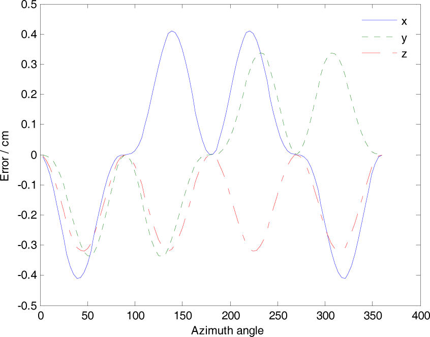
Errors in the Local Frame OPPXPYPZ

The Variation of Leg Length
5. Conclusions
Based on the new design of the three-level cable-suspended feed structure, the kinematic analysis and the simulation example presented in this paper, the following conclusions may be draw: the three-level cable-suspended feed structure can reach the requirement of the orientation of the feed source when increased to 60° from 40°. When there is an error measured in the end Oe, the Stewart platform can adjust the leg length to increase the end precision of CSFS. According to the model in this paper, a new 50m three-level feed cabin structure is under construction at Xidian University. Some experiments will be performed on the physical model to compare it with the simulation results.
Footnotes
6. Acknowledgements
The authors gratefully acknowledge the financial support received from the Fundamental Research Funds for the Central Universities (K50510040014) and the National Natural Sciences Foundation of China under Grants 51105290 and 51175397. The authors also deeply appreciate the remarks and suggestions of anonymous referees, which led to the improvement of this paper.