
Abstract
Research on the cable-driven mechanism has greatly developed with the booming of the robots in the past 30 years, and a range of corresponding theoretical studies have been published on them. The large-scale robot or manipulator with the complex cable-driven mechanism can be reconfigured. However, more theoretical studies are required on their topological architecture design and optimization to achieve this. Therefore, the applied cable-driven architectures and the corresponding theoretical studies are reviewed and summarized here. The parallel, serial, and differential architecture are illustrated, as well as their theories and methods, such as the workspace analysis based on the Jacobian matrix, particle swarm optimization and genetic algorithm, and kinematic design based on the graph theory are described. The features of the architecture and the theory studies are concluded. It is hoped that this study will help with design of future studies.
Keywords
Introduction
Cable-driven mechanisms, also referred to as tendon-driven or wire-driven mechanisms,1–6 are usually driven by actuators via pulleys and cables and have applications in a range of robots. These corresponding robots are categorized into two types: 7 serial and parallel robots. Research on serial robots has found several applications in exoskeletons and prosthetics.8–11 The parallel robot has different names such as cable parallel robot (CPR), 12 cable-driven parallel robot (CDPR), 13 cable-driven parallel manipulator (CDPM), 14 cable-driven planar parallel manipulator (CDPPM), 15 cable-actuated parallel manipulator (CPM), 16 and cable-driven parallel platform with a pneumatic muscle active support (CPPPMS). 17 Differential cable-driven type has found several applications in humanoid robots for its higher load capability and relatively more compact structure, but do not fall into the category of serial and parallel robots.
Nowadays, cable-driven mechanism is employed to develop more precise positioning systems because of their advantages such as higher precision, small backlash, and lightweight transmission. Some famous cases including the NIST RoboCrane, 18 Japanese FALCON, 5 Italian iCub,19–21 and Chinese FAST22,23 have demonstrated the feasibility. And, the literature on cable transmission theories covers a wide range, including transmission principles on power and motion, structure design and mechanical computation, kinematic analysis and design, topological optimization design, control analysis and design. Literature reviews 24 on the load/deflection behavior of pretensioned cable–pulley based on the differential slip condition and the integral slip condition. Some important conclusions such as the relationship between stiffness and pretension, soften spring behavior describe the essential transmission principles and are taken as the design criterions. The research results on the relationship between freedom of motion and the number of cables, 25 the workspace analysis theories based on the Jacobian matrix, 26 have become the design basis of the CDPR.
However, there are great challenges to employ the cable-driven mechanism to explore new products, and many research results have been achieved. It is difficult to determine the logical architecture type to be referred when facing the first design step, structure design. It can also be difficult to arrange the cables and pulleys as there are no such systematic theories to describe the relationship between the architecture and the design requirement. Therefore, the architecture design and arrangement optimization are the first to be considered and still depend on the engineers’ experiences. In this study, research relating to the topological architecture of the cable-driven robot is reviewed to clarify the knowledge about the architecture design. Three categories of classical applications are briefly introduced and analyzed to clear the main characteristics, which help to determine the architecture type. The theoretical researches on architecture design are stated from degree of freedom (DOF), Jacobian matrix, to workspace and kinematic analysis. The trends on theoretical development are analyzed and summarized. The reviewed work hopes to provide a clear understanding on the architecture design skill for cable-driven mechanism applications. The remaining contents are as follows. The applications of cable-driven robots are presented and their typical topological architectures are described in section “Applied topological architecture of cable-driven robots” and the corresponding theoretical studies on the topological architecture are summarized in section “The studies on the design method of architecture.” In the end, the conclusions are demonstrated and research trends are analyzed.
Applied topological architecture of cable-driven robots
Parallel topological architecture
CDPR was initially developed from the parallel link robot and has been widely used in a range of applications due to the ability to operate in a large motion range, high dynamics with large payload capacity and higher energy efficiency, low cost, simple structure, and safety. 27
Planar CDPR
Planar CDPR refers that the platform driven by cables and actuators moves in a plane with two or three DOFs.
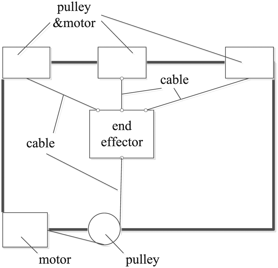
Feriba-3, whose layout is shown in Figure 1, works in the horizontal plane and is a typical planar cable-driven robot prototype of University of Padova. 6 The end effector is driven by four cables and motors mounted in the four vertices of the frame. One end of each cable is fixed on the lateral side of the end effector and may wind around the end effector, which is emphasized as heavier lines in Figure 1. And, the other end is wound on the pulley that is directly fixed on the motor shaft. The cable’s tension vector is computed according to the feedback results as a function of the actuator’s position vector, to form the expected forces and torque to drive the actuator. So as to achieve the expected controlling accuracy, a real-time program was developed for full feedback control at a frequency of 5 kHz. Each control cycle comprises pulley angular position acquisition, forward kinematic pose solution, feedback force calculation, cable tension computation, and output voltage updating.

The layout of Feriba-3.
A test prototype developed at the University of Delaware, called suspended planar robot, works in a vertical plane. 28 The layout (Figure 2) shows that the end effector is suspended by four cables, and the attachment points of the cables may be changed. Cables are driven by servo motors, each of which is fitted with an encoder through a pulley. A force sensor is set in serial for each cable to test the tension during the motion. Feedback control based on the encoders and force sensors is applied to position the end effector in the plane.
Layout of the planar cable robot developed at University of Delaware.
Three-dimensional CDPR
Three-dimensional (3D) CDPR refers that the end effector is driven by a few cables and actuators and may move in 3D space with over three DOFs. The famous 3D CDPRs are used in cargo handling and astronomy.
NIST has taken the lead to develop a series of RoboCrane robots to carry out heavy loads.18,29 Japanese FALCON 5 is a 6-DOF ultra-high speed robot. CoGiRo is developed by TECNALIA and is reported as the Europe’s biggest CDPR. 30 The common scheme of this kind of application is shown in Figure 3. A few motors and pulleys are mounted on the top of a 3D frame, and the end effector is suspended by a few cables winded with the pulleys. The motion of the end effector is determined by the length of all cables. There are various sets of arrangements of frame and there may be more or less cable and motors. The different architecture is related to the system requirements, such as workspace, repeat position precision, and velocity.
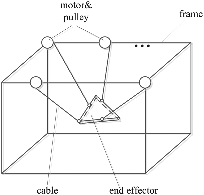
The common scheme of cargo handling robots.
Their applications in astronomy are generally for large-scale cases, such as radio telescope. FAST is a giant telescope of China and its airborne focus cabin is regarded as the largest CDPR all over the world.22,23 The cabin is dragged by six cables, each of which is driven by a motor fixed on a higher tower with tension force of tens of tons. Large adaptive reflector (LAR) 31 is a famous telescope in Canada and its airborne feedback platform consisting of a radio reflector is suspended by an aerostat and driven by eight cables and wrenches to keep its position.31–34 The common scheme of this kind of application is similar to that in Figure 3, with some supports instead of the frame. A few actuators, including motors and hydraulic actuator, are mounted on the top of the support that may be arranged as system requirement. The end effector, including telescopes or antennas, is suspended by cables. The length of the cables is controlled to adjust the posture of the end effector. The number of the support, motor, and cable, and the locating points may be configured and support height may be adjusted. This kind of the architecture design provides huge-scale workspace and may optimize the design to realize different objectives.
Features of parallel topological architecture
The topological architectures of the CDPR are demonstrated through Figures 1–3, in which the cables drive the end effector which is suspended or fixed by some supports, to realize the desired positions control or working traces. There may be different arrangements about the fixed positions of the cables and wrenches, about the routines of the cables and pulleys, and about the number of the cables and wrenches. The planar application may be regarded as a special case.
Based on the aforementioned literature, some distinct features can be drawn as follows:
Evaluated from the parallel link robots, the parallel cable-driven robots can offer a potential large workspace, high-speed motion, and being easy to reconfigure while maintaining a lightweight structure. These advantages impel more application to explore, especially in some long distance and large load cases.
Pulley is not necessary for many CDPRs. When the pulley and cable work together, they work in the open-loop mode 24 for most parallel cases. It should be noted that the specific property of cable-driven mechanism is that cables can only work unilaterally by the tension, which brings about the complicated problems about the control of the mechanisms 28 and workspace determination,35–38 and the corresponding researches are abundant.
For the parallel cable-driven robots, the relationship between the desired DOF and the number of cables is significant for the architecture design.
A drawback inherent to CDPRs is the restriction in workspace because of the potential cable interference.39,40
Serial topological architecture
Bionic limbs with parallel axes
A kind of serial cable-driven mechanism is found in the bionic robot limbs with parallel axes. The Wearable Cobot is manufactured by the Florida State University and applies three stages of the cable-driven mechanism in the shoulder and upper limb design. 11 The force/torque and motion are transferred in the series of cables and pulleys to simulate the human upper limb motion. As a medical instrument, a haptic device prototype is invented by National Technical University of Athens, National and Kapodistrian University of Athens. 8 There are a 2-DOF-linkage joint and a 3-DOF spherical joint to simulate the shoulder, arm, and hand. The two motors are designed to drive the 2-DOF links in serial to realize shoulder and upper limb motion. These classical serial applications have similar architecture to that shown in Figure 4. There are a few stages of transmission, and the rotation axis for each pulley is parallel. The motors and corresponding sensors are mounted on each axis. All rotary motions are controlled individually to simulate a certain posture or to acquire the desired trace or position.

The classical serial architecture.
Considering the motor attached to each axis increases the moment of inertia, an adapted architecture, shown in Figure 5, is accepted to improve the motion performances.9,10 All motors are mounted on the base and drive the determined axis through a series of pulleys. Tsusaka and Ota 10 compare the classical and adapted architecture and prefer the later. Although this can reduce the moment of inertia, the complex cable routines bring new design challenges.

The adapted serial architecture.
Orthotropic axes positioning platform
Based on the key technique “The Rotolok Rotary Drive,” 41 RIEtech Global, LLC (formerly Sagebrush Technology, Inc., est. 1991) has developed a series of accurate pointing platform, such as Aero 20, Model-2, Model-20, Model-30 Worm Drive, and Model 30 Rotolock, most of which have usually azimuth frame outside and elevation frame inside in serial. These products have the identical orthotropic axes architecture, shown as Figure 6. Figure 6(a) shows that there are the two orthotropic axis, azimuth, and elevation in space. Generally, both axes are driven by a mechanism as Figure 6(b). The azimuth axis may provide continuous rotation and the elevation one only limited range of angle. Load is mounted on the elevations frame and may cover a region of spherical surface. This kind of serial cable-driven applications takes full advantage of the gimbal mechanism, which greatly reduces the volume and motion inertia.

Orthotropic axes architecture for positioning platform: (a) orthotropic axes architecture and (b) cable-driven.
The features of the serial topological architecture
The topological architecture of the serial cable-driven mechanism is demonstrated through Figures 4–6, in which the joints are arranged in serial and are driven individually. The axes in the bionic robots are parallel and the motions of linkages between pulleys are in a plane. While the axes in the positioning platforms are orthotropic and the frames move spatially.
Some features about serial cable-driven robot may be summarized as following:
Applications of serial cable-driven robot focus on the limb robots, positioning platforms, and medical manipulators to pursue lightweight design while keeping high precision. Generally, the cables may be used to deliver power and enlarge the driving force in the first two types; meanwhile, they are used to transfer power only in the last one.
The pulley is usually employed not only to deliver the driving force but also to act as a gearbox to decrease the speed and increase the torque. Some cable–pulley mechanisms work in closed loop, while some work in open loop.
The limited motion range is determined by the unidirectional characteristic of the cable, and carefully designed pretension mechanism is necessary for the high-precision cases. Such a pretension mechanism increases the complexity of design and manufacture, which may occasionally result into transmission failure. Therefore, researches have been performed for pretension mechanism design to guarantee potential high dynamic precision.24,42
Differential topological architecture
Enlightened by the differential gearbox and gimbal cable-driven mechanism, people developed a differential cable-driven mechanism.
The differential cable-driven applications
In as early as 1991, an arm robot with compact differential cables is issued in the patent. 43 The principle scheme is shown in Figure 7. It uses more cables to mesh smooth outer surface pulley that have orthotropic axes of revolution. With two cables connection, the forces of pulley L and Pulley R are transmitted to pulley T, respectively. Therefore, the pulley T will rotate on the Z axis when the forces are heterodromous, while rotates on the Y axis when the forces are homodromous. Two actuators cooperate to drive pulley T, which increases the output torque. Such a differential mechanism can provide the advantages of compact arrangement and larger output torque, therefore this technique continues to be issued by more robots.44,45 Whole-arm manipulation (WAM) 45 is invented by Technology, Inc., Cambridge, MA, USA. The differential cable-driven mechanism is applied in the robot shoulder design to acquire a hollow joint arrangement to minimize the mechanical volume and increase the output torque. Similar applications have been developed in different countries, including SHERPA, 46 THAILAND, 47 and iCub.19–21

The differential scheme in the patent.
Features of differential topological architecture
The typical topological architecture is just like that illustrated in Figure 7. Pulley L and Pulley R are driven individually, and the combination of their motions determines the output platform motion through smoothly meshing between different cable–pulley sets. Especially in the bionic robotics field, the following prominent advantages of this kind of architecture are attractive:
The differential cable-driven style may multiply the output torque, which decreases the requirements for the actuators and reduces the volume. At the same time, it can eliminate or greatly reduce the backlash because of cooperative driving.
It may be designed as a hollow mechanism, whose inner space may offer rooms for electric cables arrangement to realize a compact structure. So, it is served as the motion joints in some limb robots.19–21,45–47
The arrangement of pulleys and cables may form different motion combinations, and every cable needs a pretension mechanism. Both these bring troubles in mechanical design.
The studies on the design method of architecture
The cable-driven architecture arrangements determine in large part the performance of a robot, because a poor design of cable routing may result in limited operational workspace size, high cable tensions, and large spatial volume. Many theories and methods have been developed to design or optimize the cable-driven topological architecture.
The study on the relationship between the cable number and the DOF
Although cable-driven parallel mechanism is evaluated from link parallel one, the theoretical conclusions obtained from rigid link manipulators cannot directly be applied to cable-driven parallel mechanisms due to the cable unilateral property, which results into that the relationship between the cable number and the DOF is quite different with that of rigid link manipulators. Early in 1994, A Ming and T Higuchi 25 had illustrated this relationship. Therefore, the CDPRs are classified into under-constrained, completely constrained, and redundantly constrained according to the number of DOFs of the end effector n and the number of cables m.25,48 When m is less than n+1, it is called as under-constrained robot; and when m equals n+1, then it is completely constrained, otherwise it is redundantly constrained. This principle is cited frequently 48 and taken as a design reference for many CDPR. There are different challenges for under constrained, completely constrained, and redundantly constrained robots.
Jacobian matrix and singularity analysis
The Jacobian matrix is a transformation matrix between the vector in joint space and that in end effector space. It can be used to determine which configuration the mechanism will become singular. On the physical viewpoint, the singularity for a serial robot is that the robot will lose one or more DOFs. While it may bring parallel robots for one or more DOFs. 49 More research has been conducted on parallel robots. The singularity problem is always relative to the feasibility of the motion or force, and its research is used to validate architecture design.
Jacobian matrix has become one of the most popular methods during the architecture design, especially for the parallel robots. It may be evaluated from the different ways. Geometric and kinematic relationships are used to set up the Jacobian matrix. Generally, it is consisted as the following48,50

where
The research on the singularity is evaluated from the parallel rigid robots. Such studies are summarized into three typical methodologies: the geometric methodology, screw theory, and analytical methodology. 51 Although the former two have the advantages of simplicity, they are limited to a few special constructions, such as for specified 5-DOF 52 or for Gough–Stewart platforms. 53 So, studies on the parallel rigid robots often apply a different analytical methodology to analyze the singularity distribution in the workspace.
For CDPRs, there exist Jacobian singularity and force-closure (FC) singularity. The former happens because of the rank deficiency of Jacobian matrix. While the FC singularity may occur due to the cables’ inability to generate tension even when the Jacobian matrix rank is full for the fully-constrained cable-driven robots. So, it is noted that the Jacobian singularity is defined on the kinematical viewpoint, while the FC singularity is defined on the dynamical viewpoint. 54
For the former, the rank of the Jacobian matrix is checked to study the singularity.55–60 Such theories are proved and the corresponding results are reported. 54 However, these singularity results ignore the unique unidirectional property and deem all cables as rigid links. So, these results may fail when any of the cable is in slack condition. Therefore, the latter FC singularity has attracted more research. A theorem has been put forward to avoid the FC singularity. 61 For any vector that indicates the wrenches act on the end effector, the signs of the non-zero projections of all row vectors of Jacobian matrix are not same.
Xiumin Diao62 has put forward a computer algorithm to check the FC singularity for planar CDPRs. Qiu et al. applied this theorem on the large radio telescope. After computing the workspace and analyzing the force singularity of the six-cable cabin, a tie-down cable was added to form a redundantly constrained system to eliminate the force singularity. 63
Workspace analysis and optimal design
Most of the literature on workspace analysis and optimization focuses on the subject of parallel robots. As it is known, an important reason to apply the parallel cable-driven mechanism in the robotic manipulators lies in its larger workspace. Knowledge of workspace is to plan the trajectory and determine the configuration. It should be noted that the results acquired from rigid link robots do not fit CDPMs due to the unilateral characteristic and therefore, available workspace analysis and optimization become common topics in the parallel robot research.
The definition of different workspaces
There are a few different concepts of workspace. A picture, shown as Figure 8, is depicted in Pham et al. 15 to show the relationship between some typical definitions. Generally, WS simply refers to workspace, consists of all poses where the robot is controlled and all cables are tensioned. 35 Considering the pretension limited and the actual stiffness to perform a task, WSTC and WSSC are introduced individually to identify a workspace with the tension constrains and stiffness constrains. The space which satisfies the above three spaces is defined as the feasible workspace (FWS). 15

Concepts of workspace.
When wrenches are considered, the dynamic workspace, 36 wrench-feasible workspace (WFW), wrench-closure workspace (WCW), and interference-free workspace are categorized and described.48,64 For a CDPM, the dynamic workspace is the set of all configurations of the position vector of the end effector in the Cartesian coordinate and dynamic conditions including the acceleration vector of the end effector for which all cables are in tension. 36 The WFW refers to the set of poses with positive cable tensions for a specified set of external wrenches, velocities, and accelerations, within the specified actuation limits of the cables. 48 The WCW is similar to the WFW, refers to the set of configurations in which the end effector can acquire any external wrench if there are no upper bounds for all cables tension. 48 WCW is defined as the FC workspace. 26
The basic and evaluated inequalities for workspace
The workspace (WS) of a CDPM can be determined basically through inspecting the tension of all cables. A basic equation is 48

where W is the vector of the universal force or torque,
W has different expressions according to special research objectives. If a static workspace is sought, W only includes static forces or torques. 35 When dynamical workspace or WCW is studied,28,36,48W may be expressed as 48

where M is the mass or inertia matrix, C is the centrifugal and Coriolis force vector, G is the gravitational vector, and FE is the external wrench vector.
Based on equation (2), all types of workspaces are described through different methods. For an n-DOF system with m cables, the workspace can be described as such an essential inequality

The geometrical interpretation of equation (4) is the workspace is satisfied when the rows of J may be positively spanned in R n for full rank. 48 Similar descriptions appear in the corresponding research reports. 26
A series of geometrical methods are developed to determine the workspace based on the Jacobian matrix and are reviewed and developed in Gouttefarde. 26 Five algebraic theories about nullspace and separating/supporting hyperplanes are collected.
These theories have been proved61,65–68 and have been used or evaluated to acquire the workspace for a great range of special cases.15,16,48,54,69
Analytical formulations may provide a more accurate description of workspace. Due to the algebraic complexity, it proves a little difficult to describe the analytical shape of the workspace, namely, to solve the inequality or Jacobian matrix, especially for higher DOF systems. Most analytical studies have been concerned with determining the boundary of the workspace. For a planar cable manipulator, the WCW boundary has been analytically studied.36,38,68,70–72 The boundary may be determined to be in the form of polynomials. However, some researchers7,17,64,70,73–75 would resort to the numerical analysis to acquire the direct plots, known as the point-wise evaluation methods. To save the computing time and achieve higher accuracy, a hybrid analytical–numerical approach is introduced to balance the conflict. 48
Optimal objectives on architecture
Based on the expressions of all types of workspace, researchers set up some objective functions for workspace and carry out the optimal analysis to acquire the desired architectures. Two main types of objective functions are usually proposed, one is based on desired regions of the manipulator workspace and the second based on the minimization of cable forces for desired trajectories.
The workspace volume is frequently taken as a simple measure function,15,64,74 though it may be distorted when the bound condition of the tension or stiffness is considered. The volume is numerically estimated through directly accumulated cube volume of the workspace,15,74 while a weighting function is applied 64 and the analytical–numerical method is taken to estimate the workspace volume index. 48 The global condition index (GCI) is used to judge the kinematic dexterity in the full workspace, and the connection is set up between the GCI and workspace volume.35,73,76 To improve the robot’s dexterity, it is the aim to increase GCI value.
Minimal tension index on all cables is another common optimal performance index, but different measure functions are applied.16,64,74,77 The minimization of the average cable tension or the maximal cable tension is usually employed to pursue for lower power dissipation. Namely

where |||| can be ∑Ti/m, or Max(Ti);
To compromise the workspace volume and tension distributions, weighted performance is the synthesis of a workspace index and a cable tension index 7 and is shown as

where
Optimal methods for topological architecture
Different optimal algorithms are employed to seek for optimal configuration to determine the fixed position, size, or length, to acquire the expect workspace or special orbits. For different configurations and different orientations, the workspace is evaluated and the GCI is computed, and the relationship between them is illustrated. An optimal design is determined by comparing different special cases according to the workspace performance term. 35 Non-linear forward control laws were presented to obtain the optimal cable tension configuration. A simple analytical algorithm starts with the limitations of tensions that are determined according to the positive tension condition and the motion accuracy. So 39


where fi is the force along a cable, and ui is the motor driving force. The fmax, fmin are the upper limit and lower limit of the cable tensions individually, while umax and umin are limits of the motor forces. Generally, fi is chosen as the maximal value between the fmin and the value from dynamical equation. Considering the relationship between the desired cable tensions and cable force along the cable, a correction result is introduced as the minimal controllable cable tension.
The minimum norm of the forces along the cables and the norm of the some cable forces are compared, and the convex optimization method is proposed to formulate to be easily solved according to Dykstra’s projection algorithm.77,78 The pattern search (PS) algorithm is suitable for non-smooth or discontinuous objective optimization through searching a set of points called a mesh. The cable routing points of cable-driven arm exoskeleton (CAREX) are optimized to acquire the optimal tensioned workspace. 79
To search the minimal norm of cable tension vector, two optimization methodologies, the randomized algorithm optimization methodology and particle swarm optimization (PSO) algorithm, are presented to determine an optimal cable routing. 7 The randomized optimization algorithm relates three parameters, accuracy parameter ε, level parameter α, and confidence parameter δ to the sample sizes to bound the uncertainties. The average cable tension is defined as a statistic norm, and optimal geometrical variables are searched to minimize the norm. This approach combines quantitatively the result uncertainty and the optimum accuracy to form the decision. But this is less efficiency for those of the large design space. For the PSO algorithm, a particular geometrical parameter vector X is applied to mark a particle of the parameter space. xt i and vt i refer to the position and velocity of the ith particle at time t, respectively. And, an objective function, ψ(x), reflects each particle’s position. At each time step, the function is evaluated using current position information, then vt i is updated and a new position is calculated. This repeats until convergence. The choice of the objective function depends on the design emphasis. In this article, the factors of workspace and cable tension are considered into the objective function. Although it is more complex to implement than the randomized algorithm, the PSO algorithm may avoid the probability of failure. Some experiments were performed on a 3-DOF cable-driven robot leg, and the results demonstrated the optimized cable tension for the desired tasks. The PSO algorithm becomes a common choice for the architecture optimization of the cable robot, and similar researches have been applied in a number of cases.80–82
Genetic algorithm (GA) is another popular optimal method. Standard GA is performed to maximize the stiffness or minimize the cable tension in the desired workspace, or to maximize the workspace.83–87 The GA has been evaluated through combining with other algorithms to pursue global optimal solutions or accelerate the convergence. Jamwal and Hussain 88 proposes a biased fuzzy sorting genetic algorithm (BFSGA) based on the fuzzy sorting genetic algorithm (FSGA). 89 The fuzzy theory is applied to fuzzify the objective functions and construct fuzzy-dominant fronts. This method may explore the optimal solution for the multi-objectives, including the workspace, stiffness, and actuator force. To get more explicit solution, a GA-PS is proposed in Bahrami and Bahrami. 90 The standard GA is performed to optimize the dexterity index and overall stiffness index of a spatial cable robot, and the PS is subsequently executed and starts the final solution of the GA.
Graphic theory and kinematic analysis
Kinematic analysis is usually used to check the attainable workspace or parameters to validate the mechanism design in many studies. The typical rotation transformation equations based on the Euler angles is usually applied for kinematic analysis. 91 After a linear graph theory is applied for 3D rigid-body systems by Chou et al., 92 the graph-theoretic models that are suitable for the serial and parallel mechanisms are employed in topological and kinematical studies in the multi-body systems. Network model, non-oriented and oriented graphs, and a few extended graphs models are applied to analyze the topological architecture and solve the kinematic relationships.93–99 These theories and methods promote research of the cable-driven robots.
In Cipra,
100
it is regarded that a cable–pulley system comprises three basic elements, pulleys, blocks, and cables, which are shown in Figure 9. The motion equations between the cables, pulleys, and blocks are analytically described according to the geometrical constraints. An example is demonstrated in Figure 10, where

Basic block with elements: (a) basic block (b) pulley Pi, and (c) block Bi.
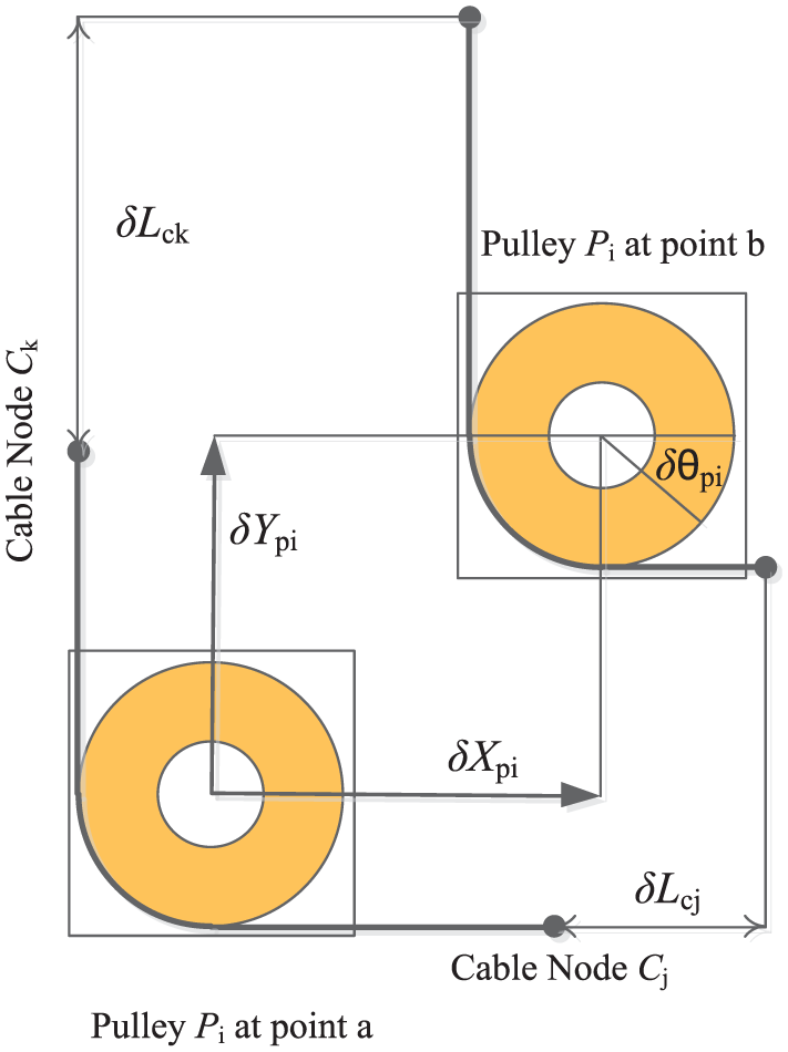
Change in position of cable nodes.
After validating the bevel-gear trains,93–99 the oriented-graph methods are utilized on the kinematic analysis of the tendon-driven mechanisms. The basic element, shown in Figure 11, is set up to present the cable–pulley unit, and the relationship between the graph and the tendon-driven mechanisms is established. An example is demonstrated and its oriented-graph model (Figure 12) is built to evaluate the kinematic equations. 2 It shows that the graph expression on kinematic of tendon-driven mechanism is similar to that of bevel-gear trains given in Uyguroğlu and Demirel, 95 and angular velocity can be directly evolved using the concept of fundamental circuit equations. The modeling method is applied for a 3-DOF and the Stanford/JPL finger and is validated. 2

Cable–pulley graph unit.

The graph kinematic model.
A serial cable-driven robot may be a metamorphic mechanism because there exist different cable routings. With a structure matrix defined, the possible routing configurations of n-DOF mechanism with m cables are shown. 3 Singular value decomposition (SVD) method is developed to determine the dimensions of tendon pulleys and tendon routing to acquire a better architecture design. A 2-DOF robotic manipulator with four cables and a planar 3-DOF robotic manipulator with five cables are, respectively, demonstrated to validate the SVD method.
The possible routing combinations increase significantly when there are numerous rigid bodies, which brings great challenge for architecture design. Therefore, a cable routing matrix (CRM) is presented to model the serial cable-driven manipulator with arbitrary link number and cable routing. 101 The CRM becomes the single representation for all possible cable routings and the kinematics and dynamics may be derived directly. Two example systems are illustrated through the inverse dynamics analysis. The results show the theoretical validity.
Summary on the topological architecture theories and methods
Obviously, the global rapid development of all kinds of robots motivates the research on theories and methods of the cable-driven systems in the recent 30 years. Some features may be perceived as follows:
There are more theories and methods research on parallel manipulators than that on serial. The topological architecture researches cover such areas as the analysis about DOF, workspaces calculation, and determination based on Jacobian matrix theories, workspace, and cable tensions optimization. The research on the relationship between the DOF and the cable number or wrench number provides the basis to perform architecture design and analysis. The main issue of the topological design is to determine the motion DOF and cable number. Based on the topological architecture, the Jacobian matrix is essential for the kinematic and dynamic analysis for the parallel robots. The workspace and tension distributions are common performances indexes, and the fixed positions on both end, and some geometry parameters, such as cable length and pulley diameter are the adjustable design parameters. There are special issues for the under-constrained parallel cable-driven robots when designing the system architecture because of the intrinsic coupling property between the kinematics and dynamics, which is not enumerated here.
The theoretical research on the serial robots mainly focuses on the modeling of their topological architectures based on the graph theory, especially for the spatial differential cable-driven robots. These theories and methods benefit the kinematic modeling, analysis, and optimization, even dynamic modeling and analysis. Especially, the routing matrix method exploits a way to study analytically on the routing arrangements optimization because a spatial cable-driven robot has become a metamorphic mechanism.
The optimization research on the topological architecture mainly focuses on the structure parameter optimization, which is generally performed after topological architecture design. The limited profits about architecture optimization provide little guidance for structure design in the beginning, especially for some complex spatial robot. The graph topology that has widely used in the electronic area may be a possible way to solve this issue. 102
Conclusion
The research on the cable-driven robots mainly grew in the last 30 years along with the worldwide developments in robotics. The cable-driven techniques are adopted by many types of robots or manipulators, which lead to the development of a range of theories and techniques. Review of their literature revealed several trends:
Research activities on parallel robots are more active. The traditional serial robots strictly cascading step by step have faded out of sight and been replaced by adopted serial and differential mechanisms.
The applications are toward large-scale or high-precision cases in the multi-dimensional space while the complexity of the mechanical and the control design has been enhanced greatly.
While the theoretical studies on the cable-driven mechanism have covered most of the research field, they do not satisfy the increasing demands of large-scale or super-precision spatial applications. The complex spatial mechanical structure becomes a metamorphic mechanism whose architecture needs to be determined through optimization selection. Also, the dynamic deflection behaviors with pretension and loads need to be described to offer the design basis for the high dynamic precise applications.
Footnotes
Handling Editor: Jan Torgersen
Declaration of conflicting interests
The author(s) declared no potential conflicts of interest with respect to the research, authorship, and/or publication of this article.
Funding
The author(s) disclosed receipt of the following financial support for the research, authorship, and/or publication of this article: This work was supported by the National Science Funding of China (grant number: 201503170138), Advanced Research of National University of Defense Technology (grant number: 2016042), and Collaborative Innovative projects of China North Industries Group Corporation and Advanced Colleges (grant number: KH201504).