
Abstract
This study aimed to analyze the kinematic development of a rehabilitation cable robot for patients with cerebral palsy problems. For this purpose, the walking pattern of a healthy person was analyzed in the robot by extracting his kinematic model. Therefore, a seven-link model was considered, and changes in the mass center of the links and then movements during the gait cycle were obtained with the angles related to joint changes. Next, the person’s integration with the rehabilitation cable robot was investigated with the resolution of the direct kinematic problem. In addition, the change-related outputs of the cables were obtained by the person’s movement and the attached belt. The robot was further proposed because the specific change diagram of the cables facilitates understanding how much motor torque is needed to change the length of the cable. It is noteworthy that the static person balance is provided in the existing rehabilitation robots. However, in this structure, the balance is done by the six degrees of freedom robot so that the robot can return the person to the original path when he loses his balance. Cable systems for the lower limbs (thighs and shanks) are also simulated to rehabilitate the patient. The obtained results from the simulation and the obtained output from kinematic equations for lower limb movements were also compared, and the highest deference was 2.2, 1.8, 1.8, and 1.5% for shank-back, shank-front, thigh-back, and thigh-front of the leg in the corresponding points in the outputs of both software, respectively.
Keywords
Introduction
Today, many people around the world suffer from severe movement problems due to brain and spinal cord injuries, complications of stroke, and neurological problems. 1 Researchers have found that performing a series of repetitive rehabilitation exercises increases efficiency in improving the function and mobility of patients. For this task, robots are an excellent option for people to do these exercises. In general, rehabilitation robots can store and process spatial, force, and velocity information to achieve the best performance for rehabilitation. 2 Also, this information can be used to compare the recovery process of a person.
One type of permanent movement disorder in children is cerebral palsy (CP), which results from congenital anomalies or damage to the brain in the early stages of development. Many people with CP 3 and some patients with stroke 4 develop other disorders and disabilities throughout their lives due to poor walking patterns and exercises. Hence, discovering and designing methods to improve gait rehabilitation is critical for patients with mobility problems. 5 Traditional rehabilitation processes require a lot of effort and time to make the rehabilitation process effective. 6 Even considering that rehabilitation is performed by the individual, repetitive rehabilitation movements may not be adequately performed due to the error and carelessness of the physiotherapist. 5 A practical method for walking rehabilitation is robotic therapy, which in recent years has introduced many rehabilitation robotic systems 7,8 that has reduced costs and improved the efficiency of rehabilitation. Another noteworthy point is that the existing robots for the weight control system always control part or all weight. This is especially important for CP patients because in CP patients, the first problem to be considered is the maintenance of upper body balance, which can be used with the capabilities of the cable robot for balance exercises.
In comparison to cable-driven parallel robots, serial robots are expansive, not easily portable, have limited workspace, but their significant difficulties are that the patients do not cope with these systems. 2,9 –11 To overcome these problems, researchers have suggested using parallel cable robots that flexible cables replace rigid links and make the patient comfortable and reduce the feeling of limitation by the rehabilitation device for the person. 2 Also, parallel robots do not have the problem of joint misalignment because they are not directly involved with human joints. 7 These features make parallel cable robots superior to serial robots, and in fact, by combining cable and parallel robots simultaneously, the advantages of both parallel robots and flexible cables can be used. 9
One of the rehabilitation robots that has reached the commercial stage is the Lokomat robot. This robot has four degrees of freedom (DOFs) and uses two motors located in the knee and near the thigh to help the patient move the leg through a healthy kinematic path. 12 The TPAD robot also helps the patient move on the treadmill by applying force to the pelvis center. The robot uses a belt that wraps around the pelvis to control the force applied to the cables with the help of cables and the camera. This robot gives the patient more freedom of action than the Lokomat robot. 13
Parallel cable robots have received much attention from researchers in the field of rehabilitation in recent years. 5,7 The configuration of such robots consists of a fixed structure and an end effector connected by cables. A cable robot sample with six DOFs was developed and practically verified by Korayem. 14 This type of structure is very suitable for rehabilitation because it has a large and adjustable workspace that makes it compatible with patients and different rehabilitation protocols. In addition, the mechanical structure of such robots can be easily assembled, disassembled, and transported. From a clinical point of view, if the patient uses a cable robot to rehabilitate him instead of wearing a device, the patient will have fewer limitations and will be able to cope more easily with this rehabilitation technology. 2,5
Few cable robots can be used for medical and rehabilitation purposes. 5 Surdilovic et al. developed a rehabilitation robot called STRING-MAN. This robot is used to help a wide range of people with mobility problems. 15 Wu et al. developed and designed a prototype cable robot called CaLT, which also had good experimental results. In this robot, the end effector was attached to the person’s ankle, and a rehabilitation operation was performed. 16 In Barbosa et al., 5 a low-cost cable-driven robot was designed with a fixed base and a movable platform for those with CP or stroke. This robot can be applied for lower limb rehabilitation. Chen et al. designed a new cable-based rehabilitation robot for patients with waist injury. However, this structure consists of four cables and pulleys responsible for controlling and moving the platform under the person. Assuming that the upper body is fixed, using an exoskeleton whose only knee joint can be changed, they perform rehabilitation for the person’s waist. 17 In another study, Cafolla et al. presented CUBE, a cable-driven device for upper and lower limb rehabilitation. This robot is designed with five DOFs and comprises six cables controlling the end effector while they assumed that the orientation is constrained by a fixed support on the Z-axis and fixed on the X and Y axes. 18 In some lower limb rehabilitation articles, the focus of rehabilitation is on specific joints of the foot. For example, Russo and Ceccarelli designed and analyzed a wearable robotic system for ankle rehabilitation named CABLEankle, 19 and in another research, Wang et al. designed a cable-driven parallel robot for lower limb rehabilitation, specifically for ankle rehabilitation, and evaluated its both static and dynamic stability. 20 Chen et al. presented a knee exoskeleton for patients with knee impairments. This robot improves human performance by enhancing the strength of the patients’ knee joint. 21
Few articles consider different joint movements individually or in combination for lower limb rehabilitation due to the size, weight, and complexity of lower limb movements 5 as well as waist movement during normal gait. Therefore, there is a need to design and develop an inexpensive robotic device that can reproduce most of the joints’ movements in combination and consider waist movement to undergo rehabilitation. At first, we studied a healthy person’s walking gait during a movement cycle, and a parallel cable robot structure for trunk and lower limb rehabilitation is proposed. The structure for waist rehabilitation comprises six cables connected directly to the belt on the person’s waist. For the lower limb, cables from the belt are connected to the thighs and shanks of a person, and the motors drive all the cables. This article does not investigate the control of cable robots since in many articles, control has been discussed, including 22,23 for the trunk and 24 for the lower limb. To obtain diagrams of cable length changes, we eventually combine a simulated person with the proposed rehabilitation cable robot.
The content of this article is categorized as follows. In the second section, a person is simulated as a seven-link biped robot, and a kinematic model is obtained. In the third section, a cable rehabilitation robot is developed. The fourth section presents the discussion, and the conclusion is discussed in the fifth section.
Seven-link biped robot model
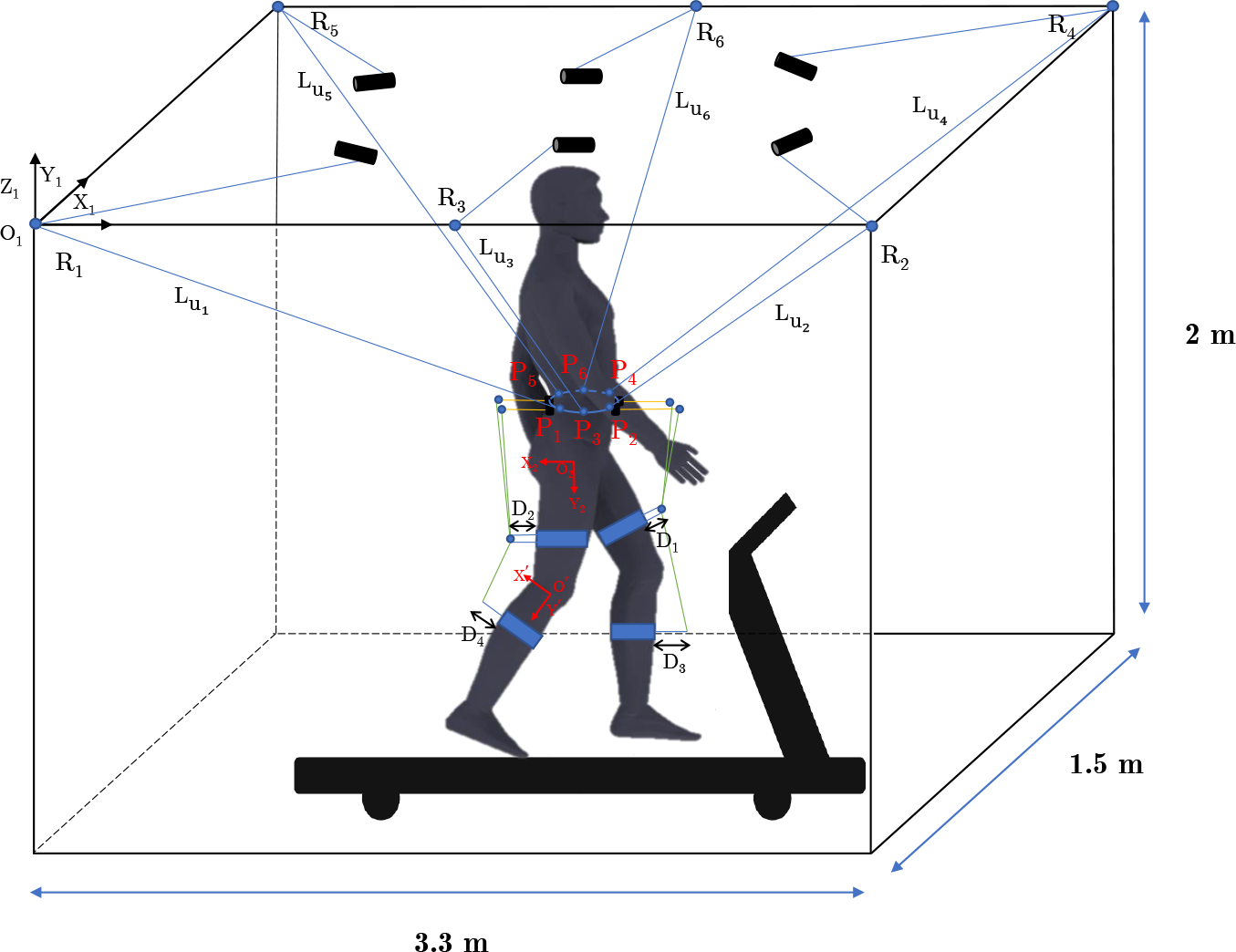
Controlling the location and orientation of the endpoint requires the kinematic equations described in this section. Figure 1 shows a parametric model of a robot in which the angles
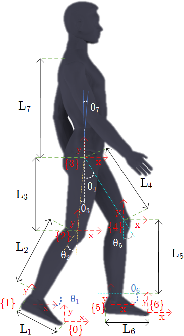
Kinematic parameters.
The dimensional values of each link are given in Table 1. These values come from anthropometry, “the scientific study of the measurements and proportions of the human body.” Anthropometric measurements are a series of quantitative measurements of the muscle, bone, and adipose tissue used to assess the composition of the body.
25
Several local coordinate systems have been used to extract the robot’s kinematic equations, as shown in Figure 1. The reference coordinate system can be assumed to be the
Dimensional values of each link. 25

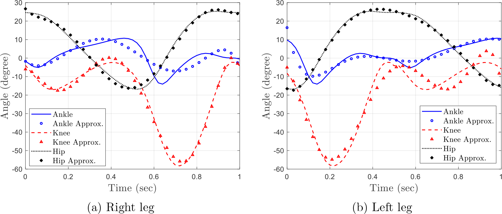
Changes in the angle of the leg joints obtained through the OpenSim software and the corresponding polynomial approximations. (a) Right leg. (b) Left leg.
To obtain the angles of the joints, the original model (gait-2392) was used as the initial model in OpenSim in order to use in walking kinematics. 26 This 23-DOF model is used to obtain the angles of the hip, knee, and ankle joints in the sagittal plane of the body. This model is a full-body model without arms and features lower extremities and trunk for a healthy person. By having joint angles and kinematic relationships, the change in mass of the links and consequently the change in cable length can be achieved for a healthy person. Therefore, by comparing these changes in the length of the cable and the centers of mass of patients, it can be understood in which movement phase an error has occurred, and according to this correct path obtained from a healthy person, the movement path of a patient can be corrected.
The seventh angle relative to the vertical line for a normal adult has a mean of 5° and ranges between
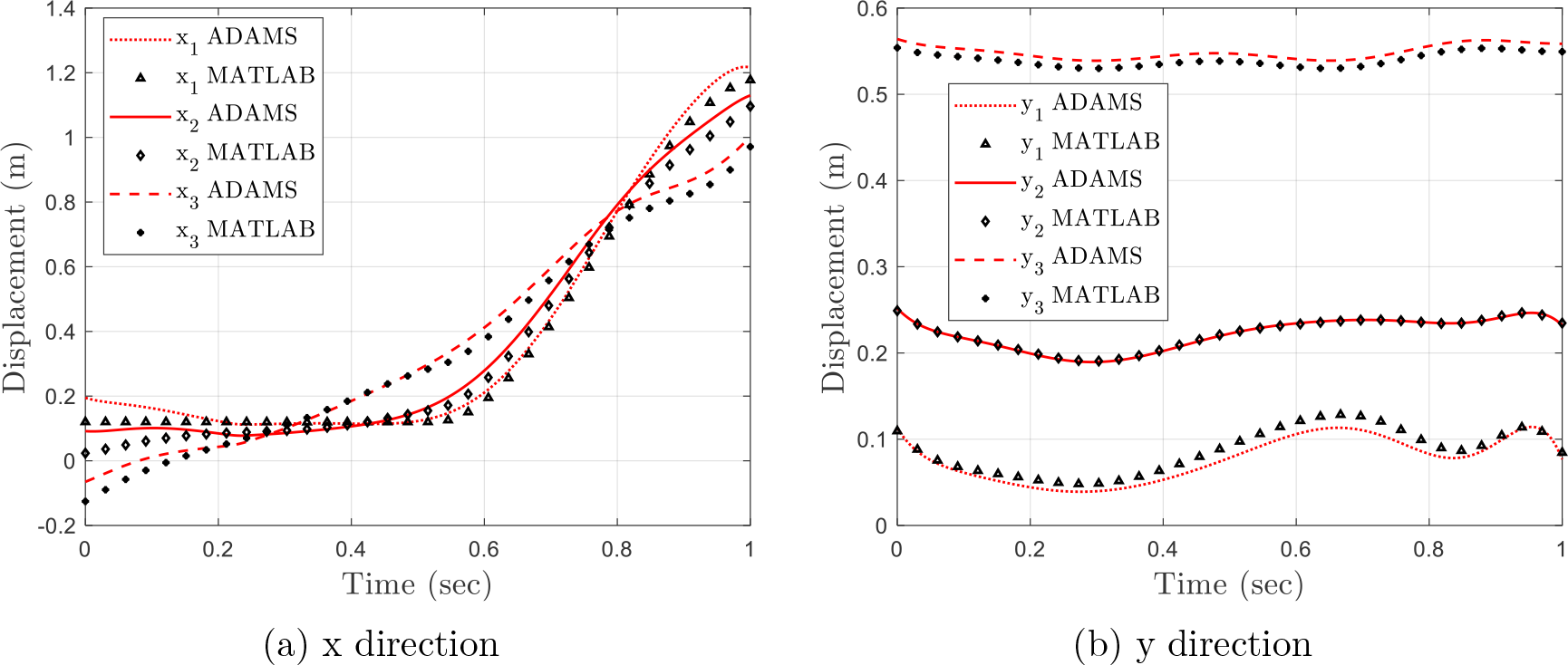
Diagram of the displacement of mass centers of the right foot links. (a) x-direction. (b) y-direction.
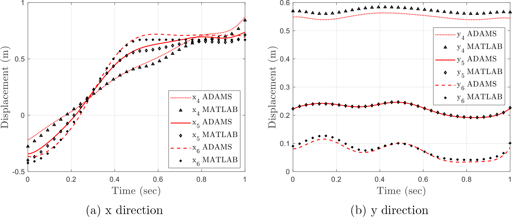
Diagram of the displacement of mass centers of the left leg links. (a) x-direction. (b) y-direction.
Rehabilitation cable robot
There are two advantages of cable robots. First, cable robots are less expensive than other robots. Today, there is a greater tendency for systems with complex electronic components and simple mechanical structures. Because electronic parts are getting cheaper day by day, but mechanical parts have a relatively constant price. Cable robots are no exception to this trend and can be drastically reduced by the mass production of these robots for use in rehabilitation centers. Another advantage of cable robots is their simple structure. They can be easily changed. 28 The connection of the cables, as well as the shape of the belt, can be changed for more comfort and more stability for the patient. Moreover, designing an inherently safe structure brings about unquestionable advantages for safety; therefore, using cable-driven mechanisms due to the highly low moving masses can decrease the risks of injuries since the errors in path planning and the robot colliding with the surrounding are notably low. 18 In the case of cable transmission, the connection of the initial points of the cables is known. Concerning endpoints, it is an assembled and integrated architecture, and the cables are fixed once before being attached to a person and worn by a person like a rehabilitation vest, which is a common method regarding rehabilitation. In general, cable-driven robots have high speed, reduced weight, good repeatability and resolution of movement, and, more importantly, high load capacity. 29
Using the belt attached to the patients and the motors that are placed on the frame, as it is depicted in Figure 6, patients can easily maintain their balance. This system acts as a counter-weight system, only neutralizes the person’s weight and balances the patient to perform lower body rehabilitation. Generally, the body weight-supported treadmill training (BWSTT) method is an effective and favorable rehabilitation method for people who have experienced spinal cord injury to ensure their balance during rehabilitation, 16,30 just like when the person is placed in the water, with the difference that not only the water resistance no longer prevents the person from moving, but also, with the help of connected cables and motors, patients can move their legs and undergo rehabilitation.
This article presents the modified prototype of a cable robot designed in the robotics laboratory of the Iran University of Science and Technology (IUST). 14 In this article, changes have been made to the ICaSbot robot available in the laboratory (Figure 5), including changing the skill of the robot to place the patient undergoing rehabilitation inside the robot. Changing the placement of cables and pulleys to optimize the efficiency of the robot, as well as adding a part of the robot to the lower body for patient movement rehabilitation. In this structure, six cables are used to control three directions and three position parameters. Six motors and six pulleys have been used for the design. Also, four support columns have been designed to support the weight of the top plate. Narrow shafts with bearings are designed to hold the pulleys on the top plate. The six cables are connected so that four of them are located in four square ends, and the remaining two are located in the middle of the two opposite sides. Figure 6 shows the general kinematic diagram of the cable robot system.

Scheme of the manufactured designed IUST cable robot. 14
General kinematic diagram of the proposed cable system.
After the person’s movement analysis is performed, a design is obtained that maintains the posture balancing with the help of a belt around the patient’s waist. The movement of the person’s waist is simulated following the movement pattern. The direction of a person’s trunk in the walking pattern is a sinusoidal function, which according to the results, this robot will respond well to this movement. In addition to not maintaining their balance while walking, people with spinal problems cannot move their legs to follow the movement pattern. Therefore, for them to move better, a system must be designed to help these people move their legs with external forces’ help. A cable system moves the thigh back, and another system moves the shank back. There are similar systems for moving forward. In other words, to move the patient’s legs, four motors are needed per leg; the motors are located at the bottom of the belt, as shown in Figure 7(a).
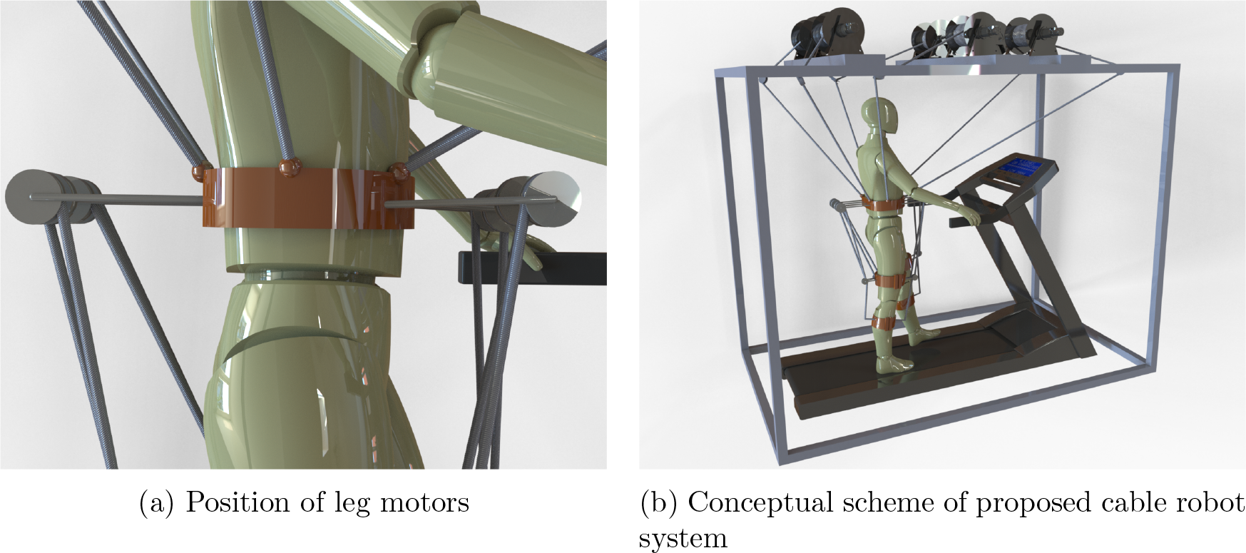
Cable robot integration system with humanoid robot. (a) Position of leg motors. (b) Conceptual scheme of proposed cable robot system.
In order to design cables connected to the back of the leg, four belts need to be attached to it, two belts around the center of mass of the thighs, and two belts around the center of mass of the shanks. In cable robots, the primary condition is the positive force of the cable. Also, for the constrained robot, the number of DOF should be less than the number of cables, and the position of cables should be such that it covers a suitable working space. The front of the leg has a similar design to the back of the leg, with the difference that in this part, the cable is more likely to hit a part of the patient’s leg when the humanoid robot moves because if the knee bends backward, the cable attached to the shank may hit the person’s knee. Nevertheless, the cable connected to the shank is more challenging, which is the same as dealing with the leg. To solve this problem, in the first step, the length of the bars is considered longer, according to the Figure 7(b). If the bars were not used, the cable would hit the knee when the knee was bent. To prevent this collision, a bar is provided so that the cable is at a safe distance from the knee while the person is going through the movement cycle. Thus, the considered bar length is the sum of the bar length in the tangent position plus 5
For the belt, a sinusoidal movement in the vertical direction is considered, which is most similar to the person’s path in the walking pattern. When a person is walking, the person’s trunk will have a slight sinusoidal movement in the vertical direction. 31 Equation (1) shows displacement along the z-axis.

The motion formula of the belt in the z-direction of the principal coordinate system is expressed in equation (1).
Cables connected to the waist rehabilitation belt
First, the coordinate axes are placed on the frame because the person is not in balance and is moving, so the coordinate axes must be in a fixed place. The coordinates of the fixed end of the cable are denoted by Ri , and the coordinates of its movable end are denoted by Pi . Therefore, the length of each cable is equal to

According to the direct movement path, this path also has moved in only one direction because the human body acts in the same way in performing the movement pattern. The first diagram of the cable length is shown in Figure 8. Since the structure is symmetrical, the graphs of cables 3 and 6, which are located in the middle of the structure and opposite each other, and cables 1, 2, 4, and 5 are equal.

Diagram of cable length changes in sinusoidal motion. (a) Cables 1, 2, 4, and 5. (b) Cables 3 and 6.
Diagrams of changes in cable angles with coordinate axes can be seen in Figure 9. The changes in these diagrams are similar to changes when the belt moves straight up. When a person is moving on a treadmill, the belt’s movement attached to him is in a vertical direction up and down, which forms a sinusoidal motion. The first diagram is a diagram of changes in the angles of six cables with the first axis of the reference coordinate system. The point in this diagram is the angles of the two facing cables in the system. As can be seen in Figure 9(a), they show a fixed angle of 90°. This is because the facing cables (middle of the sides) are perpendicular to the reference coordinate system’s first axis.

Diagram of cable angles in sinusoidal motion in the direction of (a) X, (b) Y, and (c) Z.
Then the equations for the changes of the cables connected to the leg are obtained. In general, the kinematics of cables are divided into two categories: kinematic of cables connected to the body and cables connected to the leg. The cables attached to the body are responsible for maintaining the balance of the person. The cables attached to the leg are also responsible for moving the leg to apply the leg’s desired path. The amount of leg moves forward, and backward is controlled by cables attached to the leg.
Cables connected to the lower limb
It is assumed that the cables are fully extended and that the upper body of a person, which includes the waist and belt, does not move so that the person’s legs are moving toward the body.
To calculate the length of the front cable connected to the leg, the center of coordinates and axes and the number of values required for the calculations are defined. In this position, the person is fully upright, and the legs are straight, and the vertical line from the center of mass of the leg to the thigh’s axis is perpendicular to the body’s horizontal plane. For example, the cable length change is considered for one leg for front cables connected to the right leg. The axis of rotation is assumed to be equal to the z-axis so that the positive side for the right leg is outwards of both legs. The horizontal plane of the body is assumed to be a plane parallel to the z-axis (
Cables connected to the thigh
For the position of the upper end of the front cable connected to the body, the vertical distance between the connection of the front cable to the waist to the y-axis is considered D
1, and its height to the

Defined variables for the front and back of the leg.
Now, when the person is standing, and the legs are completely straight, and along the body, the lower end of the front cable’s position is considered. The vertical distance of the lower end of the cable to the z-axis of the center of mass of the thigh (this distance is also perpendicular to the y-axis when standing D
2, and its height up to the

The first coordinate, which is related to the end of the cable attached to the waist, is always fixed to the body and equal to the mentioned values, and the coordinate of the second end of the cable is variable. The upper part of the thigh has a fixed form during movement, and the connection of the cable to this part is completely healed and does not slip. So, the cable’s downward movement can be seen as the movement of a point on the surface of a rigid body that revolves around its axis of rotation. To find the values x 2 and y 2, the distance from the lower cable tip to the rotation axis is calculated in a completely upright position. Since the movement of the leg is the same as the motion of a rigid object around the axis of rotation of the thigh, this point has a fixed distance from the z-axis, which is equal to

The angle of the leg and its rotation measure is assumed to be


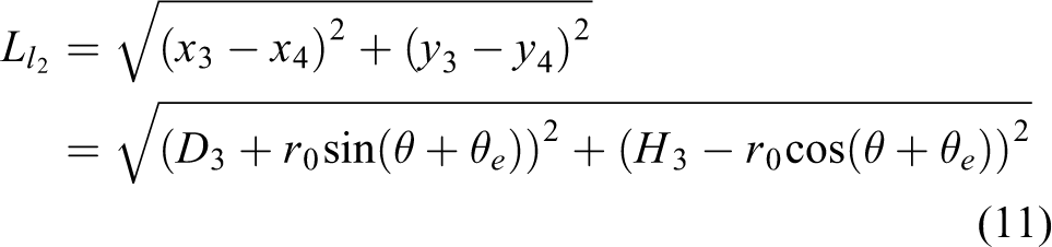
Therefore, equation (3) is equal to

The same can be done for the rear leg cable to get equation (11). The lower part of the front cable also has a deviation as much as


The change in the length of the right leg cable is obtained based on the
To obtain diagrams related to the length change of cables for a healthy person, the changes in the angles of the joints of the person as provided in the previous sections are used in the ADAMS and related equations for the designed person. Figure 11 displays the cable length changes related to the thigh. The related cable is connected to the motor on one side and the thigh belt on the other side, and by moving the motor, the thigh can be moved relative to the waist.

Diagram of the length of the cable connected to the (a) back-thigh and (b) front-thigh.
As shown in Figure 11(a), the length of the cable connected to the thigh decreases at the beginning of the movement. This is because the diagram is drawn for the person’s right leg, and the leg is initially in front of the person’s body. After decreasing, the chart rises again, meaning that the right leg continues to move forward for about half a cycle until the movement cycle ends. According to the Figure 11(b) chart initially takes a downward trend because at first, the person’s thigh is in the back, and with the initiation of the movement cycle, the leg moves forward, and the length of the cable is reduced. It will then return to its original position, and the cable length will increase. According to the equations extracted for the joints, the time of this movement is such that it completes a movement cycle in one second, which is why the diagram shows the changes in cable length in one second.
Cables connected to the shank
The quantity D
4, as defined in the previous section, is the vertical distance from the y-axis of the thigh to the center of the pulley. The value of d is the vertical distance from the center of the leg to the knee’s axis of rotation. The angle
According to the definitions and Figure 12, we can write

Defined variables for the shank.
To have the components of this cable end relative to the first coordinate axis, it is necessary to use the transfer matrix (DENAVIT-HARTENBERG) between these two axes. Therefore, the distance between the centers of coordinates o and


According to the initial assumption, the coordinate centers, as well as the centers of mass of the two legs, are all on the same plane. And according to the definitions, the x and y axes and the

The matrix of equation (14) becomes the matrix of equation (15)

The location of the cable’s end attached to the shank in the second coordinate axis is in the form of equation (16)

Now absolute position will come from the multiplication of the transfer matrix in the equation (16) compared to the axis of the first coordinates

Therefore, by multiplying the matrices, the following equations are obtained


Hence, changing the length of the shank rear cable is equal to

For front cables also due to
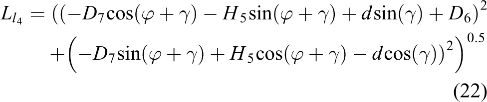
Figure 13(a) shows the cable length change for the back-shank. The difference in this cable system is that this cable is not connected directly to the shank. At first, the cable is pulled to the thigh by a pulley. In this part, another pulley is installed. After moving around the second pulley, the cable is attached to the belt around the shank at the thigh. Two graphs are used to obtain the length of the cable connected to the shank. One diagram is the cable’s length from the motor to the pulley located in the thigh belt, and the other is the diagram of the length of the cable from the thigh to the shank. The first diagram is the same as Figure 11(a). That must be added to the second diagram. If the two graphs are plotted together point by point, Figure 13(a) is obtained.

Diagram of the length of the cable connected to the (a) back-shank and (b) front-shank.
The knee joint’s considerable thing is that the shank cannot bend forward and only go backward. The length of the cable at the beginning of the movement cycle is about 82 cm. The cycle then reduces this length to about 57 cm. The cable’s length is reduced by 23 cm, and it can be said that this is the shortest length of cable connected to the back of the shank. After this reduction in length, which is a change in the swing phase at the minimum point, the cable length increases again. This time the chart reaches its maximum value in 0.3s, which is 83 cm. The chart is divided into two parts: the stance phase, which starts from the beginning of the movement and lasts up to 0.65s. After the minimum point, the phase change occurs at the same time and enters the swinging phase from the stance phase. It will then remain in this phase until the end of the movement in one second until the end of the movement cycle, and in fact, the person has taken one step.
For the same reason, the cable length diagram attached to the front-shank entails two length changes. One of these changes is related to changes in length at the top of the leg or between two pulleys, and the other is related to the cable length changes related to the distance between the thigh and the shank. Therefore, the final graph is obtained from the result of these two changes mentioned (Figure 13(b)). In this figure, the cable length increases first. This is because the resulting graph results from two other graphs, and the beginning of the knee movement cycle bends more than the location. Therefore, the cable’s length increases, then the leg moves forward, which reduces the length of the output, and the leg returns to its original position.
Discussion
This article focuses on developing a novel cable-driven robotic gait training structure for both waist and lower limb that simulates waist motion behavior despite most previous studies that have kept the waist steady and fixed. The fact that the robot uses cables for rehabilitation provides a wider workspace and brings about more reliability. Additionally, by knowing the changes in cable length obtained from the gait behavior of a healthy person, in case of discrepancies and errors, by using the correct path, the walking behavior of the patients can be corrected. To testify and validate the model, we simulated a person’s moving and applied it to the ADAMS. Also, we obtained the governing equations of cable length and compared these outputs. Firstly, for the trunk, the graphs of cable and angles changes are entirely matched.
Cables connected to the back of the leg consist of two cable and pulley systems. One of these cables is used to move the thigh, and the other is used to move the shank. Each of these has a diagram that shows the changes in cable length in the same movement cycle. Figures 11(a) and 13(a) show a comparison of the cable changes for back-thigh and back-shank, respectively. In Figure 11(a), the two plots are approximately similar. In Figure 13(a), in the lowest part of the graph, a slight difference of about 1.3 cm can be seen.
In rehabilitation, equation (1) shows the waist displacement along the z-axis, which has been used in kinematic equations and ADAMS to simulate the waist behavior of a healthy person. However, as mentioned earlier, for lower limb cables, changes in joint angles derived from OpenSim need to be assumed as functions of time in order to be applied as inputs to the joints in the simulation. While in kinematic equations, these data related to angles are used as inputs to kinematic relationships. Using the approximated polynomial function in the simulation causes a slight error in the shape of the graphs. While for waist belt cables, only the waist behavior, which is represented by equation (1), affects the shape of the diagram of changes in the length of the waist belt cables, and this equation is applied as an input in both software environments. Therefore, these can make a difference for lower limb cables in the two approaches, which is shown in Figure 13.
Similarly, Figures 11(b) and 13(b) show a comparison of the cable changes for front-thigh and front-shank, respectively. The only difference between the front and back cable systems is the length of the rods attached to the thigh, and the shank belt at the front of the leg is slightly longer than the back ones. Figure 11(b) shows the cable length change for the front-thigh, which two plots are nearly analogous. The maximum difference of 0.4 cm in Figure 13(b) is due to the reasons mentioned before. On the other hand, the graphs’ trends play a more significant role in the rehabilitation operation, and it can be concluded that the directions of the diagrams are close to each other. Numerous articles have examined the closed path of the ankle in the patient’s walking cycle. 16,32 This is because the patient is following the path of the healthy person correctly when the last part of the ankle (end effector) follows the correct path. For the purpose of further verification, Figure 14 shows the closed path of ankle trajectory in a movement cycle at the time of application to the patient. Figure 14(b) consists of two graphs obtained from kinematic equations and simulation, which are similar to each other. Moreover, these two graphs are precisely like the closed path mentioned in the articles and confirm the correctness of the diagrams obtained from equations and simulations.

Ankle path: (a) ankle trajectory of a person and (b) ankle diagram.
Conclusion
The primary idea of this article is to help patients with spinal cord injury or stroke. Since these people need help to recover their lost power, a cable-based robot has been studied and suggested to help these people. As mentioned before, cable-driven rehabilitation devices (CDRDs) in comparison to robotic rehabilitation devices (RRDs) have relative advantages, including large workspace and simple architecture. The main purpose of this article is to analyze and develop a body weight support (BWS) system for posture improvement and a rehabilitation cable robot for the lower limb. Since a person was needed to ensure that the proposed cable robot worked efficiently, we simulated a person as a seven-link humanoid robot, which can be moved by changing the joints’ angles. For posture balance, the proposed robot has a belt and six cables attached to the belt, which is around the patients’ waist.
In addition, to help to maintain the stability of the person, these cables and belt can be used to control the walking gait and correct his moving behavior. Also, for lower limb rehabilitation, we considered two cables for thighs, which are comprised of front and back cables for each thigh and two other cables attached to each shank of the patients to control and monitor the walking behavior. Besides, the robot would help the person and modify the way the person moves when he needs help to walk or whenever his walking behavior is different from a healthy one. Since the cable length change equations were also extracted to validate the proposed model, a comparison was made between the cable length changes resulting from the equations and the cable length changes obtained from simulation. The proposed model differs from the mathematical model for the lower limb cables by a maximum difference of 2.2 for the back-shank, 1.8 for the front-shank, 1.8 for the back-thigh, and 1.5% for the front-thigh. Eventually, by obtaining the length of cables and their changes during the normal gait of a healthy person, we could apply these movements to a person with a spinal cord injury with the help of the robot’s motors, and the rehabilitation operation is performed, and finally, real construction example can be achieved. The final goal in the development of robots, especially rehabilitation robots, is to build a robot and evaluate it in clinical issues, and our ultimate goal is no exception to this rule. Nevertheless, in this article, the required simulations have been performed to ensure the obtained results since constructing a robot is a costly and time-consuming process. In the continuation of the work, according to the assurance of the results, this proposed robot will be built and assessed for practical tests in clinical trials.
Footnotes
Declaration of conflicting interests
The author(s) declared no potential conflicts of interest with respect to the research, authorship, and/or publication of this article.
Funding
The author(s) received no financial support for the research, authorship, and/or publication of this article.