
Abstract
This article presents the locomotion analysis and optimization of actinomorphic soft robots, which are composed of soft arms actuated by shape memory alloy wires. The soft arm that is a composite modular structure is actuated by a self-sensing feedback control strategy. A theoretical model was established to describe the deformation of the soft arm, combining the Euler–Bernoulli beam model of the soft arm with the constitutive model and the heat transfer model of the shape memory alloy wire. The kinematics of the actinomorphic soft robot was analyzed using the modified Denavit–Hartenberg method, and the motion equation of the actinomorphic soft robot was presented based on the quasi-static hypothesis. Results show that the actinomorphic soft robot moves with a zig-zag pattern. The locomotion of four actinomorphic soft robots with three to six arms was analyzed, and the gait parameters of each locomotion type were optimized. The optimization results indicate that the three-arm actinomorphic robot with certain gait parameters has the best performance and achieves a maximum stride length of 75 mm. A series of experiments were conducted to investigate the movement performance of the three-arm actinomorphic robot in various environments.
Introduction
Currently, robots are employed in an extensive range of applications from manufacturing to domestic service. Conventional, rigid-bodied robots are typically composed of rigid links and joints, and they could perform tasks that require speed and precision in manufacturing. But rigid-bodied robots often lack compliance and are unsafe for human-centered tasks. Soft robots, primarily composed of soft materials, provide an alternative to bridge the gap between humans and machines. 1 Soft robots have a continuous deformable structure and result in conforming to unknown objects and conditions. Soft robots are attracting the attention of many researchers due to their promising applications and satisfactory performance. 2 –5
The actuation is one of the key issues for soft-robotic systems. Various actuators have been used to develop soft robots such as pneumatic actuation, dielectric elastomer actuators (DEAs), ionic polymer metal composite (IPMC), electroactive polymer actuators, and shape memory alloy (SMA) wires or springs. 6 –9 A pneumatically actuated robot fabricated by soft lithography has been demonstrated to navigate obstacles by combining a crawling gait with undulation gaits. 10 Soft grippers based on DEAs have been designed to manipulate deformable, fragile objects of any shape. 11 A pectoral-fin-mimicking manta ray consisting of a polydimethylsiloxane (PDMS) membrane using four IPMCs has been developed to achieve the undulating locomotion. 12 A robotic insect inspired by a flea has been built to achieve jumping on water using planar SMA actuators. 13 Compared with other types of actuators, SMAs cannot only offer a high power-to-weight ratio and miniaturize the mechanism but also generate explosive force. In addition, SMAs have diverse crystal structures under different phases (such as the martensite phase and austenite phase), 14 suggesting that the electrical and mechanical properties of SMAs vary with their phase transformation. Based on these properties, SMAs can achieve self-sensing feedback control, 15 –18 where SMAs can act as both an actuator and a sensor. Therefore, SMAs are suitable for engineering and technical applications in various fields. 19 –22
Recently, many soft robots have been designed for different functions. Some robots may serve as manipulators and complete grasping tasks, such as a simple gripper, 23 a soft robot arm, 24 and a soft hand, 25 whereas others may achieve good locomotion, such as walking, rolling, jumping, and swimming. A pneumatically actuated, quadrupedal soft robot has been fabricated to achieve walking gait in a variety of adverse environmental conditions. 26 A caterpillar-inspired soft robot can generate rolling locomotion using SMA coils. 27 A tripedal soft robot has been demonstrated to achieve jumping locomotion using a chemical reaction. 28 An octopus-inspired, multi-modal, soft robot can perform shape-changing pulsed-jet propulsion and benthic legged-locomotion based on a hybrid least squares/genetic algorithm-based method. 29 These soft robots own good locomotive performance and show potential for many potential applications (such as environmental monitoring or search and rescue operations).
Many soft robots, which show good performance, are inspired by biological systems. For example, a fluidic elastomer robotic snake has been developed to synthesize the interesting locomotion gait of snakes. 30 An inchworm-inspired robot has been designed to achieve both two-way linear and turning movement. 31 A turtle mimetic soft robot driven by flipper actuators has been proposed to produce distinct motions corresponding to different swimming gaits. 32 A miniature jellyfish-inspired robot can achieve a diversity of propulsion modes using jet propulsion. 33 In the biological locomotion field, symmetry is one of the typical features, such as the bilateria and the radiata. Among these creatures, the radiata (e.g. brittle star and starfish) achieves a high mobility for the radial symmetry of its body. As the shape of the radiata is actinomorphic, its gait pattern can be easily modularized. However, a few studies have been conducted on the locomotion of the actinomorphic soft robot. A starfish-like soft robot has been developed to achieve multigait movements. 34 However, it moves slowly in various terrains. A soft robot inspired from the starfish has been designed to achieve various locomotions. 35 However, the locomotion mechanism of the soft robot is not analyzed.
This article investigates the locomotion of the actinomorphic soft robot composed of soft arms and the effect of gait parameters on the locomotive performance of the actinomorphic soft robot. First, actinomorphic soft robots with different number of soft arms were designed with a layer casting technique, and a self-sensing feedback control strategy was adopted to modulate the bending range of the soft arm. Then, theoretical models were established including the model of the soft arm and the kinematics as well as the motion equation of the actinomorphic soft robot, to analyze the motion of the actinomorphic soft robot. Furthermore, each locomotion type corresponding to each actinomorphic soft robot with a specific number of arms was presented, and relative gait parameters were optimized to select the one with the best performance. In addition, a series of experiments were conducted on a three-arm actinomorphic soft robot to investigate its basic movements and performance in various environments.
System design of actinomorphic soft robots
Design and fabrication of actinomorphic robots
Actinomorphic soft robots with three to six arms were designed as shown in Figure 1. Each actinomorphic soft robot is primarily comprised of two parts: soft arms and a regular polygon rack. The soft arm was fabricated by a molding technique and a layer casting technique. 36 Their soft bodies were manufactured using PDMS (Sylgard 184, Dow Corning [Shepherdsville, Kentucky, United States]), and a thin polyvinyl chloride (PVC) polymer plate was embedded in PDMS. These soft robots were actuated by SMA wires (diameter of 0.15 mm, a transition temperature of 90°C; Flexinol® nickel–titanium alloy wires by Dynalloy, Inc., Irvine, California, USA). Multiple SMA wires can be connected in a parallel or serial system. 37 It could increase the force capabilities of the SMA actuator to connect SMA wires mechanically in parallel. 38 However, the power supply requirement may be affected by such an arrangement. Besides, this arrangement has a negative effect on the motion of the actinomorphic soft robot for the wires at the end of the actuator. Therefore, SMA wires were arranged in M-shaped layouts with a serial manner. Racks were fabricated via three-dimensional (3D) printing technology with acrylonitrile butadiene styrene plastic in the form of regular polygons. Table 1 lists the sizes and masses of these soft robots.

Structures of actinomorphic soft robots. (a) Fabrication of the soft arm. (b) Actinomorphic soft robots with multiple arms.
Body sizes and masses of actinomorphic soft robots.

Actuation strategy of the soft arm
Figure 2 shows a circuit diagram of the self-sensing feedback control strategy for actuating the soft arm. An STM32F103 processor was employed to send the control signal via the PWM output and measure the voltage VS via the analogue input. A MOSFET IRF540 module, acted as the switching element, was used to control the heating or cooling state of the SMA wire. A precise resistor RS was connected in series to the SMA wire to indirectly measure the resistance of the SMA wire during the actuation process. The effect of the MOSFET on the circuit can be neglected when the on-resistance of the MOSFET is low. A direct current (DC) voltage source (model GPR-3060D) was used to supply a DC voltage for the SMA wire. In the following experiments, the input of the SMA wire is described by the supply current that is equal to the supply voltage VCC divided by the initial resistance.
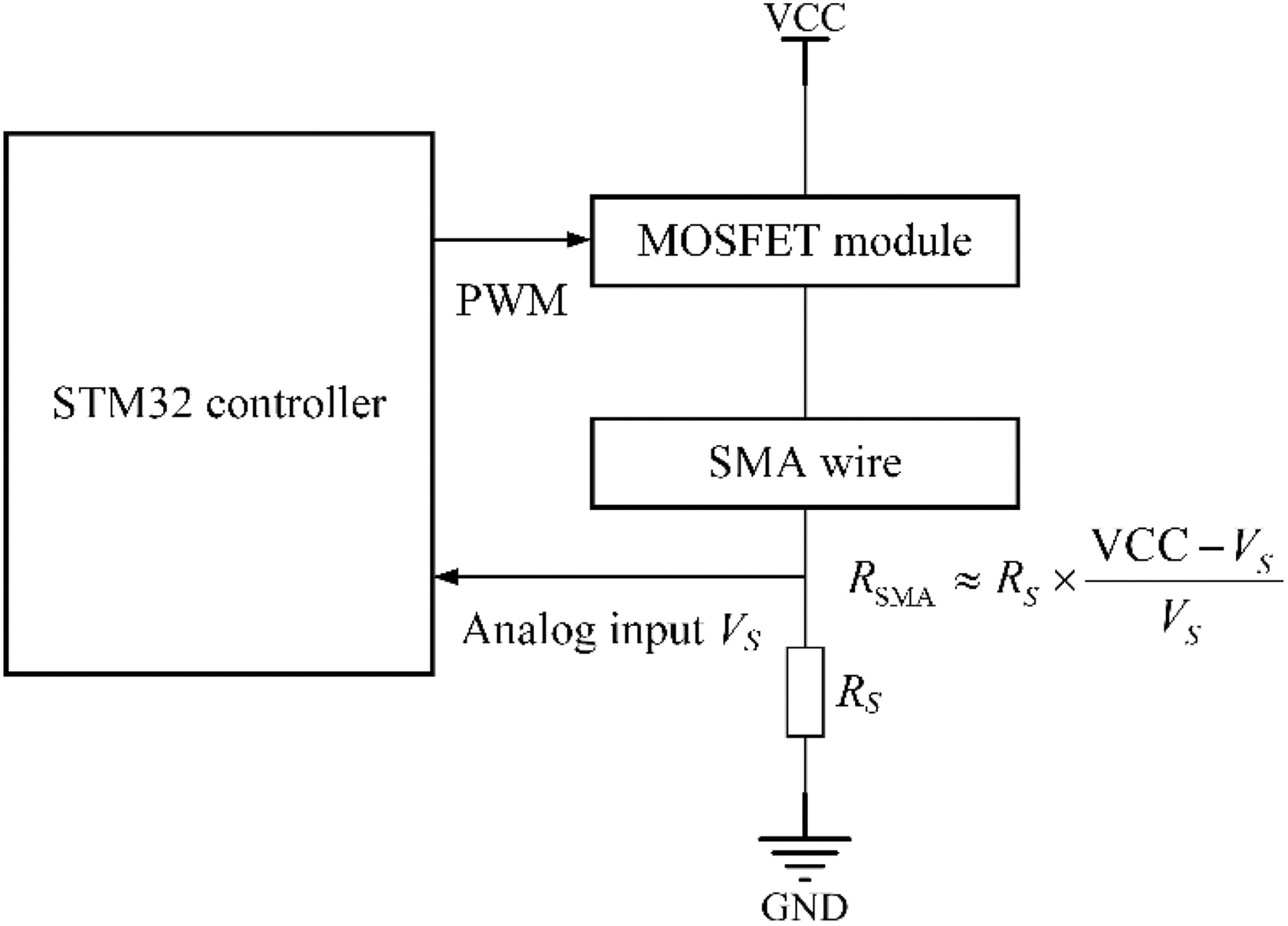
Circuit schematic of the self-sensing feedback control strategy.
Actinomorphic soft robots follow a wave gait while moving according to the sequential diagrams, in which each arm has two processes: a heating and a cooling process. In the heating process, a rapid fluctuation occurs in the SMA resistance when the SMA wire of the soft arm undergoes a phase transformation. Therefore, the deformation of each arm can be regulated. The set duty cycle is high during heating and low during cooling. The switch controller shown in Figure 3 can switch between these two processes according to the sequential diagrams. Here, the high duty cycle was set to 100%, and the low duty cycle was set to 0.

Control block diagram of one arm for walking.
In the heating process, the SMA resistance exhibits a regular variation when the soft arm is under a nonloaded condition, as shown in Figure 4(a). Within the ranges of A–B and C–D, the SMA resistance is primarily affected by temperature. Within the range of B–C, the SMA resistance decreases monotonously because of the occurrence of phase transformation dominating the change of the SMA resistance. A normalized resistance λ is utilized between the maximal resistance and the minimal resistance, as shown in Figure 4(a). Figure 4(b) shows the bending range of the soft arm from B–C, which is the angle between the final and initial bending angle. The bending angle β is used to quantify the bending range δ. According to Figure 4(b), the bending range of the soft arm is in an approximate linear correlation with the normalized resistance. Based on these properties, the self-sensing feedback control strategy was adopted to control the soft arm. The bending range of the soft arm was modulated by limiting the analogue input VS (λ). VS (λ), which can be directly measured, decreases monotonically with the SMA resistance

where V min is the minimum value of the voltage VS across the precise resistor in the experiment, and R SMA (λ) can be obtained using


Properties of the soft arm under idling (supply current = 1.54 A, RS = 1 Ω, at room temperature of 27°C). (a) The resistance and normalized resistance of the SMA wire versus time in the heating process. (b) Bending range of the soft arm versus the normalized resistance of the SMA wire in range B–C. SMA: shape memory alloy.
The analogue input VS (λ) was applied as a threshold value to modify the duty cycle, and therefore, the bending range could be regulated. In addition, the overheating of the SMA wire could be prevented with the self-sensing feedback control strategy.
Locomotion analysis of the actinomorphic soft robot
Model of the soft arm
Many researchers have conducted studies of the bending actuator embedded with SMA wires. 39 Taking geometric nonlinearity of the actuator and hysteretic nonlinearity of the SMA wire into account, the model of the bending actuator is established. 40 A dynamic model of the actuator associated with the constitutive characteristic of the SMA wire is built. 41 A model based on the constitutive model of the SMA wire is established. 42 However, they neglect the latent heat of transformation. Here, a model is developed to obtain the bending capability of the soft arm. Figure 5 shows a schematic of the soft arm deformed by a contraction force of SMA wire, and the parameters of this soft arm are listed in Table 2. Three assumptions are made in the model: (i) the soft arm behaves as a Euler beam throughout the bending deformation, and its bending shape is approximated as a circular arc; (ii) the PVC surface is the neutral plane of the soft arm, and the distance d between the SMA wire as well as the PVC surface is constant during actuation; and (iii) the temperature variation of the PDMS is negligible if the heating time is short.
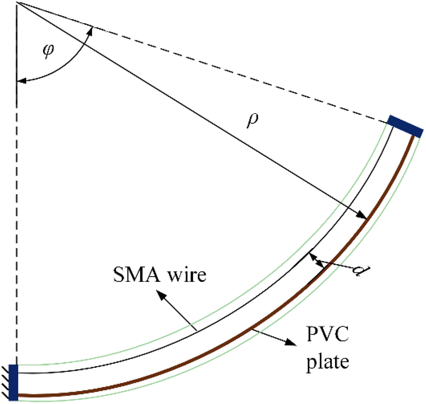
Schematic of the soft arm after actuation.
Parameters in the model of the soft arm.
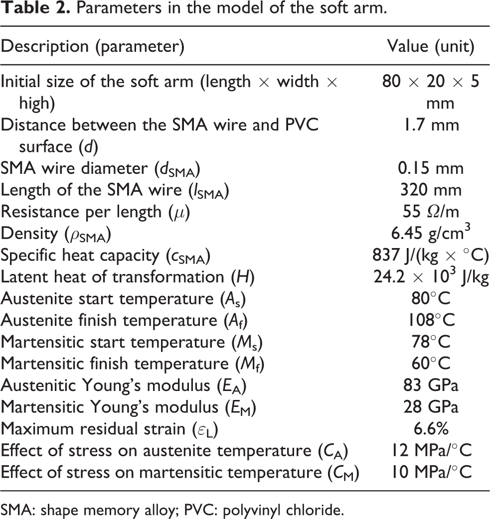
SMA: shape memory alloy; PVC: polyvinyl chloride.
When the soft arm is deformed by a bending moment generated by the contraction force F SMA of the SMA wire, with its bending deformation measured by the bending deformation φ, then
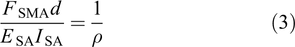
where E SA is the effective elastic modulus of the soft arm, I SA is the area moment of inertia of the soft arm, and ρ is the radius of curvature of the soft arm. Because the bending shape of the soft arm is approximated as a circular arc, the radius of curvature ρ is given by

where L SA is the length of the soft arm. The bending deformation φ can be approximately expressed by

where εSMA is the strain of the SMA wire and εL is the maximum residual strain of the SMA wire.
According to equations (1) to (3), the contraction force of the SMA wire is

The equilibrium state of the soft arm is given by

where σ SMA is the stress in the SMA wire, A SMA is the cross-sectional area of the SMA wire, and F ini is the initial pull force of the SMA wire.
The resulting stress of the SMA wire is

where
When the temperature of the SMA wire is higher than the austenite start temperature A s, the SMA wire starts to transfer from the martensite to the austenite phase and generates the contraction force. The behavior of the SMA wire is described by Liang–Rogers model 43

where E(ξ) is the Young’s modulus of the SMA wire, Θ is the thermoelastic tensor for the SMA wire and is assumed to be negligible, T is the temperature of the SMA wire, Ω(ξ) is the phase transformation tensor, and ξ is the martensite fraction. E(ξ) is assumed to be linear with the martensite fraction, namely

During the transformation process of the SMA wire from the martensite to austenite (M → A), its martensite fraction is expressed by

where
During the transformation process of the SMA wire from the austenite to martensite (A → M), its martensite fraction is expressed by

where
Therefore, the derivatives of equations (11) and (12) can be expressed by

where


When the SMA wire is heated through current, its thermal model can be expressed by

where ρ SMA is the density of the SMA wire, c SMA is the specific heat capacity, V SMA is the volume of the SMA wire, i SMA is the supply current, R SMA is the resistance of the SMA wire, h is the heat transfer coefficient, S SMA is the surface area of the SMA wire, T amb is the ambient temperature, and H is the latent heat of transformation of the SMA wire.
During the actuation process of the SMA wire, the following equations are derived from equations (8) to (16)
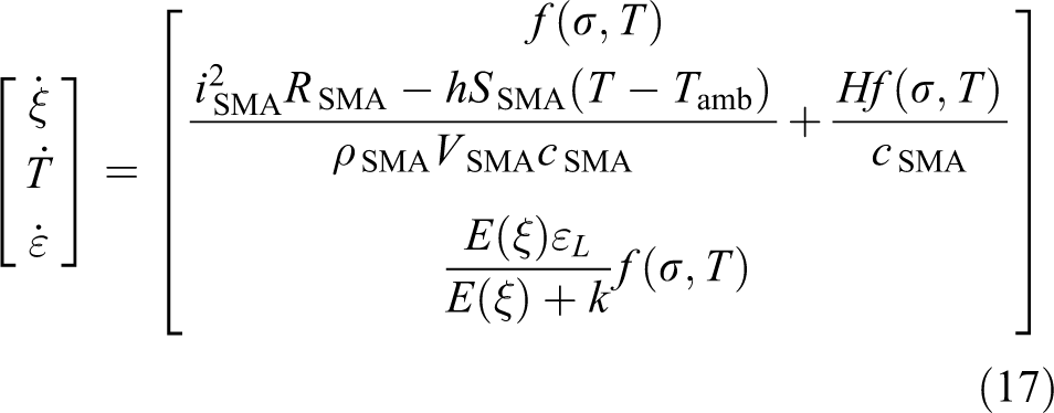
where

Figure 6 shows the bending range of the soft arm under idling, in which the supply voltage is 30 V with 160 ms heating time in one period. According to Figure 6, the cooling process is longer than the heating process and the bending range is approximately linear to the time during the heating process. The experimental and simulation results exhibit similar motion, and therefore, the model of the soft arm could be used to analyze the locomotion of the actinomorphic soft robot.

Bending range of the soft arm versus time under idling (heating time = 160 ms, period = 2 s, supply current = 1.54 A).
Spatial robot kinematics
To model the kinematics of the actinomorphic soft robot, a modified Denavit–Hartenberg (D-H) method was introduced. The modified D-H method is first proposed to model the kinematics of continuum robots, in which the movement of a planar curve is described by three coupled movements. 44 To reflect a correct orientation term, the continuum robot section is based on a rigid-link arm consisting of two revolute joints with intersecting axes, followed by a translational and two more revolute joints with intersecting axes in the modified D-H method. 45
The kinematics of the actinomorphic soft robot is analyzed. The geometric parameters for one arm of the actinomorphic soft robot shown (see Figure 7) are listed in Table 3. XYZ-system is the world coordinate system, and the actinomorphic soft robot moves in the YZ plane. Frame 0 is located in the geometric center of the 3-D printing rack, in which axis x 0 is parallel to axis X. α 1 is the angle from z 0-axis to z 1-axis about x 0-axis, which is related to the distribution of the arm. The soft arm is described by a pseudo-rigid link with a coupled link/joint arrangement. Using the D-H table, the homogeneous transformation matrix for the arm can be written as

where
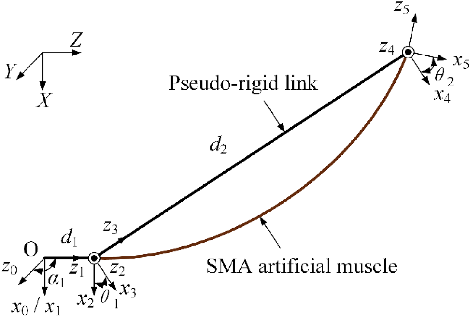
D-H frames for one arm of the actinomorphic soft robot. D-H: Denavit–Hartenberg.
D-H table for one arm of the actinomorphic soft robot in Figure 7.

D-H: Denavit–Hartenberg.
Locomotion state and motion equation
In the movement of the actinomorphic soft robot, the arm owns two states: swing and supporting state. In the swing state, the arm is off the ground. In the supporting state, the arm could be static or moving depending on the friction force with the ground. The locomotion state is a series of arm states that enable the actinomorphic soft robot to move in the environment. To analyze the locomotion model of the actinomorphic soft robot, an equivalent parallel closed-chain mechanism was proposed, as shown in Figure 8. The ground, the supporting arm, and the 3D printing rack with the swing arm correspond to the frame, link, and end effector of the closed-chain mechanism, respectively. The linkup between the supporting arm and the 3D printing rack is approximate to a revolute pair. The linkups between the ground and the static or moving supporting arm are the revolute pair and cylindrical and planar pair, respectively.

Schematic of an equivalent parallel closed-chain mechanism for an actinomorphic soft robot.
The total degrees of freedom (DOF) in the equivalent closed-chain mechanism is given by
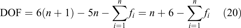
where n is the number of supporting arms, and

If all the supporting arms are moving, then
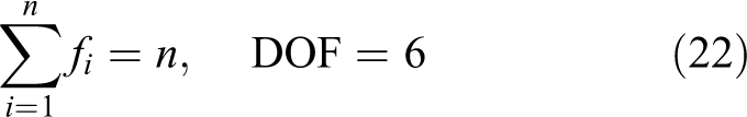
If there is one static supporting arm, then

If there are two static supporting arms, then
Therefore, during the movement of the actinomorphic soft robot, the locomotion state of the actinomorphic soft robot falls into two categories: all arms are in the moving state and only one arm is the static supporting arm.
During the movement of the actinomorphic soft robot, the bending state of the arm changes with the temperature of the SMA wire, resulting in the variation of the support force and frictional force exerted on the arm. When the state of force equilibrium is broken in the current locomotion state, the soft robot switches from the current locomotion state to the other state in which the equilibrium condition could be satisfied. The switch between locomotion states is related to the state of force equilibrium and input signal of the soft arm.
When the actinomorphic soft robot moves slowly in the environment, its motion is approximated to a quasi-static process. In the quasi-static process, the resultant

Combined with the model of the soft arm and spatial robot kinematics, the relative position of each arm end relative to the frame 0 could be calculated, and therefore, 2n-3 distance equations could be derived. The distance equation between two arm ends in the world coordinate system satisfies

where

When there is one static supporting arm, solutions of these equations could be expressed by

where k is the index of the static supporting arm, fky and fkz are the static frictional forces exerted on the arm k.
Figure 9 shows the locomotion of a three-arm soft robot, in which only one arm is actuated. The sequential diagram is shown in Figure 9(a), in which the period is 2 s with the pulse width 160 ms. The displacement of the three-arm soft robot is shown in Figure 9(b). The experimental and simulation results exhibit similar locomotion characteristics with a zig-zag movement pattern (see Figure 9(b)), due to the switch of the locomotion state caused by the variation of the support force and frictional force. Nevertheless, the stride lengths in one period of the three-arm soft robot in experiment and simulation are different. This is mainly caused by several factors including the quasi-static and pseudo-rigid approximation in the simulation scene and the variable friction coefficient affected by the changing contact surface of the arm in the experiment.

Locomotion of a three-arm soft robot with one actuating arm. (a) Sequential diagram for the locomotion (pulse width = 8%, period = 2 s, supply current = 1.54 A). (b) Displacement–time curve in the Z direction.
Gait optimization of actinomorphic soft robots
Gait planning for locomotion
Controlling the locomotion of soft robots is challenging because of the difficulty in accurate modeling of the robot–environment interaction. The robot locomotion is formulated as a type of optimization problem, 46 complex for a multiarm robot such as a six-arm robot, and some of the locomotion is not realistic. Robot locomotion is typically inspired from biology. 31,32 Inspired by starfish locomotion, two rays are pushed in advance, with three rays behind; or three rays pushed in advance, followed by two rays. 47 According to this principle, wave gaits were adopted; these actuated the soft robots in a sequential manner with an actuation wave travelling through their bodies from the front toward the rear.
Figure 10 depicts the locomotion of four types of actinomorphic soft robots. These sequential diagrams exhibit a series of wave gaits. Figure 10(a) shows the sequential diagram of a three-arm soft robot. First, arms 2 and 3 are activated and bent, thereby causing the center of gravity to move ahead. Second, arm 1 is activated and bent; this action helps accumulate the elastic potential energy to drive the robot to move forward. Figure 10(b) displays the sequence chart of a four-arm soft robot. First, arm 4 is activated and contracted; the contraction produces forward movement to cause the center of gravity to shift ahead. Second, arms 2 and 3 are activated and bent simultaneously to upraise the body. Third, arm 1 bends and drives the robot crawling motion using the accumulated elastic potential energy. Figure 10(c) shows a five-arm soft robot that moves forward with the wave gait. First, arms 4 and 5 are activated and bent, thereby causing the center of gravity of the body to shift forward. Next, arms 2 and 3 are activated and contracted to hold the entire body. Finally, arm 1 is activated and bent, thereby storing elastic potential energy to cause the entire body to move forward with ground friction. Figure 10(d) shows a six-arm soft robot that achieves forward motion via a series of sequential movements. First, arm 6 is activated and bent, thereby causing the center of gravity of the body to move ahead. Next, arms 4 and 5 are activated and the body raised. Subsequently, arms 2 and 3 are activated and contracted to hold the body. Finally, arm 1 is activated and contracted, thereby accumulating elastic potential energy to propel the robot forward. In Figure 10, Ti (i = 1, 2, 3, 4) is the period of motion in each locomotion; tij (i = 1, 2, 3, 4; j = 1, 2, 3) is the time interval of the startup time between two adjacent groups of arms in each locomotion; and Δtij (i = 1, 2, 3, 4; j = 1, 2, 3, 4) is the heating time of each arm.

Locomotion of actinomorphic soft robots. (a) to (d) are sequential diagrams of the locomotion principle for the three-arm, four-, five-, and six-arm robots, respectively.
Performance comparisons of the actinomorphic soft robots
Four types of actinomorphic robot prototypes were designed to investigate the effects of factors, for example, the number of arms and Δtij , on the performance of the robots. A series of experiments were conducted to select the optimal gait parameters to actuate robots with a satisfactory performance. The heating time Δtij of each arm was regulated by controlling the corresponding normalized resistance λij of each arm according to the self-sensing feedback control strategy, and λij corresponds to Δtij . The period of motion Ti in each locomotion is sufficiently long to prevent the SMA wires from overheating, and these periods were set as 2, 2, 2, and 4 s for three-, four-, five-, and six-arm robots, respectively. To simplify the experiments, the time intervals tij were defined to be equivalent in each locomotion, such as t 21 = t 22, t 31 = t 32, and t 41 = t 42 = t 43, and arm 1 of each robot bent with a maximum bending range, namely, the corresponding normalized resistance λ was set to 1. Several sets of experiments were performed to evaluate the effects of the time interval and heating time on the performance of robots. The time interval tij ranged from 10 ms to 100 ms with an increment of 30 ms, and the normalized resistance λij (which was used to regulate the heating time) ranged from 0.1 to 1.0, with an increment of 0.3. These experiments were conducted on a flat surface at the room temperature of 27°C.
Appendix Tables 1A to 1D list the stride lengths in one period of different robots to accomplish locomotion for the conditions stated in the previous paragraph. According to Appendix Table 1A, the three-arm soft robot could achieve better performance (a longer stride length) when the parameters satisfy the conditions of 0.1 ≤ λ 12 ≤ 0.4 or 70 ≤ t 11 ≤ 100. In Appendix Table 1B, the four-arm soft robot could exhibit better performance when 0.1 ≤ λ 22 ≤ 0.4 or 70 ≤ t 21 ≤ 100. Appendix Table 1C shows that the five-arm soft robot performs better when 0.4 ≤ λ 33 ≤ 1.0 or 0.4 ≤ λ 32 ≤ 0.7. As shown in Appendix Table 1D, the six-arm soft robot could perform better when 0.4 ≤ λ 43 ≤ 1.0 or 40 ≤ t 41 ≤ 100. These results indicate that the gait parameters affect the performance of actinomorphic soft robots with multiple arms.
The maximum periodic stride lengths of the three-, four-, five-, and 6-arm robots are 75, 72, 63, and 58 mm, respectively. Figure 11 shows the displacement–time curves of these robots at the maximum periodic stride lengths, in which the displacements are the trajectories of each center of rack (CoR). These robots exhibit similar locomotion characteristic with a zig-zag movement pattern. Their CoRs move forward for a short distance initially and then backward for a long distance. Afterwards, their CoRs move forward for a long distance and then backward for a short distance. As a result, the CoRs move forward for one stride length. The average stride lengths of the three-, four-, five-, and six-arm robots are 52, 47, 28, and 29 mm, respectively, as shown in Figure 12. The average stride length of the three-arm robot is greater than that of the four-arm robot, and the six-arm robot has a similar average stride length as the five-arm robot. Among these robots, the three-arm robot shows the best performance.
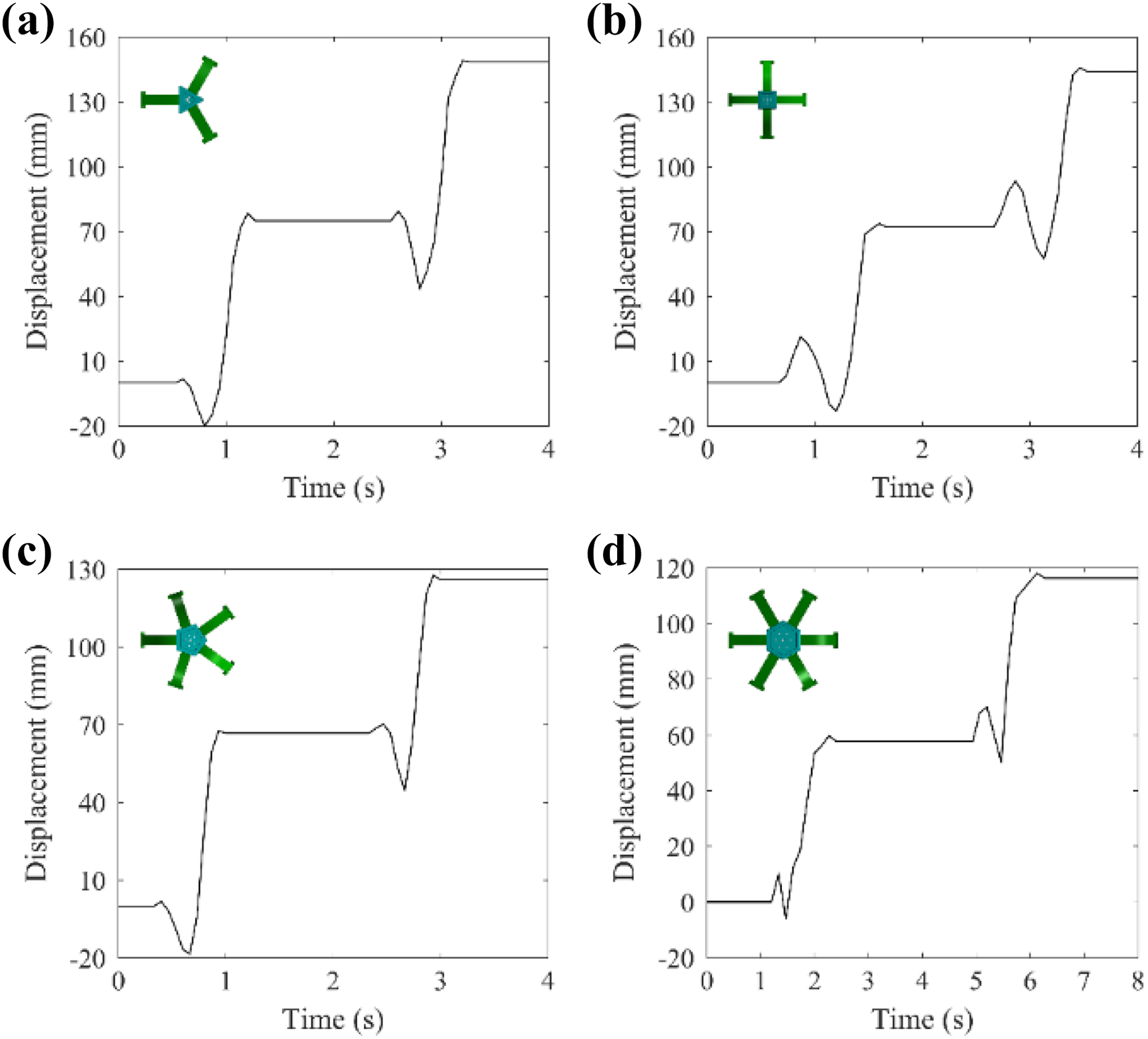
Displacement–time curves of actinomorphic soft robots for forward translation: (a) to (d) are displacement–time curves of the three-, four-, five-, and 6-arm soft robots, respectively.

Average stride lengths of actinomorphic soft robots.
Locomotive performance of the three-arm actinomorphic soft robot
In the natural environment, actinomorphic animals inhabit a wide range of surroundings, for example, sandy beach, tidal pools, and deep-sea floor. The actinomorphic animals show different locomotive performance in different environment. Here, a series of experiments were conducted with the three-arm actinomorphic soft robot to analyze the locomotive performance under different circumstances.
In addition to moving in a flat terrestrial environment shown in previous experiments, the actinomorphic soft robot could move in a semisubmerged environment, as shown in Figure 13(a). The actinomorphic soft robot could achieve locomotion with an average stride length of 33 mm at a frequency of 1 Hz, as shown in Figure 13(b). In addition, the displacement of the actinomorphic soft robot exhibits a zig-zag trend at an average speed of 33 mm/s.

Locomotion in a semisubmerged environment. (a) Frames of locomotion in the semisubmerged environment. (b) Displacement–time curve for forward translation in the semisubmerged environment.
Sand is one ordinary intertidal zone habitat for actinomorphic animals, such as starfish. The three-arm actinomorphic soft robot could move on sand. Figure 14(a) shows a sequence of snapshots of locomotion on dry sand, and Figure 14(b) shows the displacement–time curve of the robot moving on dry sand at a frequency of 1 Hz. On dry sand, the soft robot could achieve locomotion with an average speed of 5.2 mm/s. Figure 15(a) shows a sequence of snapshots of locomotion on wet sand, and Figure 15(b) shows the displacement–time curve of the robot moving on wet sand at a frequency of 1 Hz. On wet sand, the soft robot could achieve locomotion with an average speed of 22.4 mm/s. These experimental results indicate that the performance for the actinomorphic soft robot moving with a zig-zag pattern on wet sand is superior to the performance for the actinomorphic soft robot moving on dry sand.

Locomotion on dry sand. (a) Frames of locomotion on dry sand. (b) Displacement–time curve for forward translation.

Locomotion on wet sand. (a) Frames of locomotion on wet sand. (b) Displacement–time curve for forward translation.
Transitional environment is one of the common terrains encountered in nature, for example, the water–land transitional zone. Figure 16(a) shows images from an experiment of a three-arm actinomorphic soft robot operating in a region transitioning from wet sand to a semisubmerged environment. Figure 16(b) shows the displacement–time curve for the forward translation from the wet sand environment to the semisubmerged environment. In this experiment, the soft robot moved at a frequency of 1 Hz. The soft robot could achieve locomotion with an average speed of 45 mm/s in the transition region and the performance in the transition region was superior to the performance in the other two surroundings.
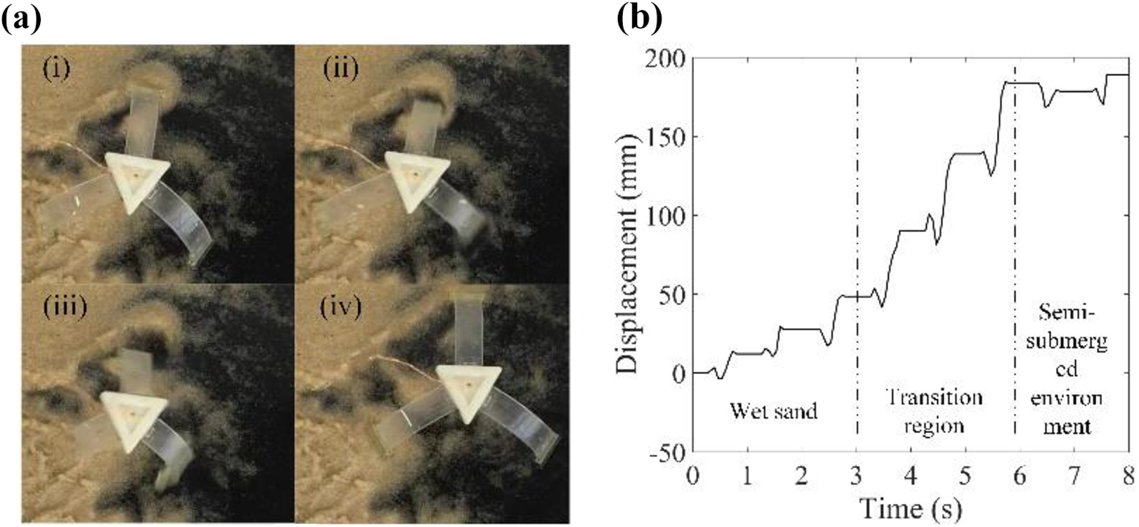
Moving from the wet sand to the semi-submerged environment. (a) Frames of locomotion in the environment. (b) Displacement–time curve for forward translation.
Moving from the wet sand to the semisubmerged environment. (a) Frames of locomotion in the environment. (b) Displacement–time curve for forward translation.
Conclusion
A model was established to analyze the locomotion of the actinomorphic soft robot, combining the model of the soft arm with the spatial kinematics and the motion equation of the actinomorphic soft robot. Experimental and simulation results show that the actinomorphic soft robot moves on a flat surface with the zig-zag pattern caused by the switch of the locomotion state. Besides, the parameters of the wave gait for four actinomorphic soft robots with three to six arms were optimized according to the criterion of stride length. The three-arm actinomorphic soft robot outperforms other types of robots and could achieve a maximum stride length of 75 mm, which is nearly 0.4 times its body length. Moreover, the three-arm actinomorphic soft robot could achieve locomotion under different circumstances, including the semisubmerged environment, dry and wet sand as well as the transitional environment. Results show that the three-arm actinomorphic soft robot exhibits similar locomotion characteristic with the zig-zag movement pattern in various environment. Future work will focus on enhancing the autonomy and mobility of the actinomorphic soft robot.
Footnotes
Acknowledgement
The authors would like to thank Dr Hu Jin for his support and advice in writing this article.
Declaration of conflicting interests
The author(s) declared no potential conflicts of interest with respect to the research, authorship, and/or publication of this article.
Funding
The author(s) disclosed receipt of the following financial support for the research, authorship, and/or publication of this article: This work was supported by the National Natural Science Foundation of China (nos. 51105349 and 61375095).