
Abstract
We developed a 1-DOF power assist robot system for lifting objects by two humans cooperatively. We hypothesized that weight perception due to inertia might be different from that due to gravity when lifting an object with power-assist because the perceived weight differs from the actual weight. The system was simulated and two humans cooperatively lifted objects with it. We analyzed human features such as weight perception, load forces, motions etc. We found that the robot reduced the perceived weights to 25% of the actual weights, and the load forces were 8 times larger than the actual requirements. The excessive load forces resulted in excessive accelerations that jeopardized the performances. We then implemented a novel control based on the human features, which was such that a virtual mass exponentially declined from a large value to a small one when subjects lifted objects with the robot and the command velocity exceeded a threshold. The novel control reduced excessive load forces and accelerations and thus enhanced performances in terms of maneuverability, safety etc. The findings may be used to develop power assist robots for manipulating heavy objects in industries that may augment human's abilities and skills and may improve interactions between robots and users.
1. Introduction
1.1 Object Manipulation in Industries
Manipulation of heavy objects is common and necessary in industries and households such as agriculture, forestry, mining, construction, manufacturing and assembly, transport and logistics, military, disaster and rescue operations, meat processing etc. Manual manipulation of heavy objects is very tedious, causes health problems (e.g., back pain, injuries) to humans and restricts work efficiency [1]. On the contrary, autonomous systems usually do not provide required flexibility in object manipulation [2]. Hence, we argue that suitable power assist robots may be conveniently and efficiently used for handling heavy objects in industries because a power assist robot reduces perceived heaviness of lifted objects through its assistance and also augments human's abilities and skills in object manipulation [3]. However, such robots are not available in practices in industries.
1.2 Present Applications of Power Assist Robots
Power assist robots assist humans perform tasks by augmenting human's abilities and skills. This type robot was first conceived in early 1960s with the invention of “Man-amplifier” and “Hardiman”. However, the progress of research on this field is not so satisfactory [3]-[5]. Power assist robots are now confined to a few applications such as healthcare, rehabilitation etc. [6]-[10]. Few power assist systems are available for other applications e.g., assisted slide doors for automobiles [11], assist for lifting baby carriage [12], assist for workers in agricultural jobs [13], hydraulic assist for automobiles [14], power assist control for bicycle [15], skill-assist in manufacturing [16], assist for sports training [17], assisting carpentry workers [18], assist for horse training [19] and so forth. However, suitable power assist systems for handling heavy objects in industries are not seen.
1.3 Robot-Assisted Object Manipulation
A few power assist devices are available for handling objects [20]-[25]. However, most of them have not been designed targeting the manipulation of heavy industrial objects. They have also limitations. For examples, human features are not included in control, the system is itself heavy, amount of power assistance is unclear, the system is not evaluated properly for safety, maneuverability, efficiency etc. [22]. Again, the system has disadvantages of pneumatics, hydraulics etc. [22]. The system generates excessive power [23]. Operator's intention is not reflected in control, and the system generates vibrations [24]. Human force is not measured directly and separately, the system restricts movement due to constraints, there are difficulties in path planning, object handling speed is slow etc. [25]. We think that these systems are not suitable for lifting heavy objects in industries because they are not sufficiently safe, natural, stable, easy and human-friendly. Few power assist systems are commercially available such as HAL [41], PLL [42] etc., but they are not suitable for manipulating heavy and large industrial objects due to their configuration, self-weight etc.
Moreover, there are several common issues with power assist systems e.g., actuator saturation, noises, disturbances, user adjustment, selection of appropriate control methods, accuracy, capacity, number, configuration, and sensitivity of force sensors, number of degrees of freedom, stability etc. that should be addressed. However, the conventional assist systems do not adopt any holistic approach to address these issues.
Other types of robot systems may be available for object manipulation. But, they are not power-assist systems, and hence, power-assistance cannot be obtained from them [26]. These robots are also not designed targeting industrial object manipulation.
1.4 Requirements for Power-Assisted Object Manipulation
We think that the requirements for power assist systems for manipulating heavy objects in industries are that the systems should ensure (i) optimum perceived heaviness, (ii) optimum manipulative forces, (iii) optimum motions, maneuverability, stability, safety, naturalness, ease of use, comfort (absence of fatigue), situational awareness of user, efficiency, manipulating speed etc., (iv) flexibility to adjust with objects of different sizes, shapes, mass etc., (v) necessary DOFs in object manipulation such as vertical, horizontal, rotational, (vi) adjustment with worst-cases, uncertainty, change of situations, disturbances etc., (vii) fulfillment of operator's biomechanical needs etc [3],[38]. However, we do not see any initiatives that fulfill these requirements entirely.
1.5 Weight Illusion in Power-Assisted Object Manipulation
A power assist robot reduces the perceived weight of an object lifted with it [3]-[5]. Hence, the manipulative forces required to lift the object with power-assist should be lower than that required to lift the object manually [27]. However, the human cannot correctly perceive the weight of object before lifting it with the robot and eventually applies excessive load force (vertical lifting force). The excessive load force results in sudden increase in acceleration, fearfulness of the human, lack of stability and maneuverability, injuries, fatal accidents etc. However, the existing power assist systems do not consider the weight perception issue [20]-[25].
1.6 Cooperative Manipulation of Objects
In industries, workers use one hand (unimanual) or two hands (bimanual) to handle objects and sometimes two or more workers handle objects cooperatively. Workers decide grasping and manipulation method on the basis of object's size, mass, shape etc. as well as of task requirements [28]-[30]. We assume that weight perception, load forces and motions for one method may be different from that for others, and the differences may affect the control performances. We also assume that out of three manipulation methods (unimanual, bimanual, cooperative), the cooperative manipulation may be the most beneficial because this method may provide advantages over others in terms of perceived weights and load forces (cooperative manipulation produces least perceived heaviness and load force) [28]. Again, the cooperative manipultion may be the most suitable when manipulating large size and intricate shape objects.
Few works addressed manipulation of a single object with a robot by a single human [20]-[25]. Cooperative manipulation of a single object by two robots was also studied [31]. Handling an object by two hands of a single human was investigated [29]. However, cooperative manipulation of an object with power-assist by two or more humans is not found though this type manipulation is very necessary in industries and households.
1.7 Objectives of the Paper
Hence, we see that it is necessary to have a model of power assist system for lifting objects. Control of the system should include weight perception, load forces and motion features to make it human-friendly. Again, as the ccoperative lifting is to be the most beneficial, the model should be based on lifting an object by two humans cooperatively. However, such model has not been proposed yet. We took an initiative to study cooperative lifting of objects with power-assist by two humans [32]. However, the study was neither complete nor exclusive for cooperative manipulation of objects.
Hence, the objective of this paper was to model a power assist system for cooperative lifting of objects with it by two humans, and to design and implement a weight-perception-based novel control strategy to improve its performances. We developed a 1-DOF power assist system for lifting objects. We included weight perception in robot dynamics. The system was simulated and two humans cooperatively lifted objects with it. We critically analyzed human features such as weight perception, load forces and object motions. We then implemented a novel control scheme that reduced excessive load forces and accelerations and thus enhanced performances in terms of maneuverability, safety etc. Then we proposed to use the findings to develop power assist robots for handling heavy objects in industries that might help fulfill the requirements, would augment human's abilities and skills and would improve interactions between robots and users. This paper does not state that no system is existed for manipulation of heavy industrial objects, rather the objective is to propose a power assist system that (i) specializes for cooperative handling of very large and heavy objects, (ii) overcomes the limitations of the existing systems, (iii) fulfills all the requirements of object manipulation, (iv) improves human-friendliness, safety etc. through inclusion of human features in control design etc.
2. Experiment System Design
We developed a 1-DOF (vertical up-down motion) power assist system using a ball screw actuated by an AC servomotor (type: SGML-01BF12, made by Yaskawa, Japan). The servomotor and the ball screw were coaxially fixed on a metal plate and the plate was vertically attached to a wall, which is shown in Fig.1 (a). We made three rectangular boxes by bending aluminum sheets (thickness: 0.5 mm). These boxes were lifted with the power assist robot system and they were called the power-assisted objects (PAOs). The dimensions (length x width x height) of the boxes were 6 × 5 × 16cm, 6 × 5× 12cm and 6 × 5 × 8.6cm for the large, medium and small size respectively. Top of each box was covered with a cap made of aluminum sheet (thickness: 0.5 mm). The bottom and back were open. Self-weight of each box was about 13g on average. A force sensor (foil strain gauge type manufactured by NEC Ltd., Japan) was tied to the ball nut of the ball screw. As shown in Fig.1 (b), an object (box), at a time, could be tied to the force sensor through an object holder and be lifted by a human.

The power-assist device. (a) shows the main power assist device. Back of a PAO (medium size) is also shown as an example. (b) shows the complete power assist device. A human grasps the PAO as it is shown.
We also made three ‘manually lifted objects’ (boxes) (MLOs) of different sizes (small, medium, large) as shown in Fig.2. The MLOs were lifted manually and were not physically connected to the power assist system. The shape, dimensions, material and outlook of a MLO of a particular size were same as that of the PAO of that particular size. However, it was possible to change the weight of the MLO by attaching extra mass to its back while keeping its front view unchanged. MLOs were used as reference weights for estimating the perceived weights of the PAOs called the power-assisted weights (PAWs).

The MLO. The photo at left shows the back and the photo at right shows the front views of the large, medium and small MLOs respectively. Extra masses attached to the backs of the MLOs are also shown as examples. The extra mass helps change the weight of the MLO while keeping the front view unchanged.
The complete setup of the experimental power assist system is shown in Fig.3. Figure 4 shows the final arrangement for the experiments for cooperative lifting of objects with the system. The PAO tied to the force sensor is to place on the soft surface of a table before it is lifted. Two handles are perpendicularly attached to the left and right sides of the PAO. Two subjects can grip two handles with their dominant hands using power grips and may synchronously lift the PAO. The MLO is to place beside the PAO so that the MLO can be used as reference weights for estimating the perceived weight of the PAO (PAW). The power assist system is covered with a cloth except the PAO in order to eliminate any visual difference between PAO and MLO.

Experimental setup of the complete 1-DOF power assist system for lifting objects.

Arrangement for cooperative lifting of object. Two subjects can synchronously lift the PAO (A) by gripping the handles with their right hands and then can estimate the perceived weights of the PAO independently by comparing its weight to that of the MLO (B).
3. Weight-Perception-Based Dynamics
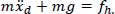
According to Fig.4, the targeted equation of motion for lifting a PAO is (1).
Where,
fh = Resultant load force applied by two humans
m = Actual mass of PAO visually perceived by humans
xd = Desired displacement of the PAO
g = Acceleration of gravity
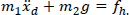
As an attempt to introduce weight perception in dynamic modeling, we hypothesized (1) as (2), where m1 ≠ m2 ≠ m,m1 « m, m2 « m, and hence m1ẍd ≠ m2g. Both m1 and m2 stand for mass. m1 forms inertial force and m2 forms gravitational force. A difference between ml and m2 is assumed due to the difference between perception and reality regarding the weight of the object lifted with the power assist robot. The human errs when lifting an object with the power assist robot because the human considers that the actual and the perceived weights are equal. However, the perceived weight is less than the actual weight. The hypothesis means that the human errs because he/she considers that the two ‘masses’ used in inertia and gravity forces are equal to the actual mass of the object (i.e., m1 = m2= m). We assume that, in order to realize a difference between actual weight and perceived weight, the human needs to think that the two ‘masses’ used in inertia and gravity forces are different and are less than the actual mass. It means that the dynamics should consider m1 ≠ m2 ≠ m, m1 « m, m2 « m. However, it would be the challenge to optimize the values of m1 and m2 to produce satisfactory feelings in humans when lifting objects with the robot by humans. We then derived (3) ~ (5) based on (2).


4. Control System Design
We then diagrammed the control based on (3)~(5), as shown in Fig.5. If the system is simulated using Matlab/Simulink in the velocity control mode of the servomotor, the command velocity (ẋC) to the servomotor is obtained by (6), which is fed to the servomotor through a D/A converter. The servodrive generates the control law based on the error displacement (xd-x) following the velocity control with position feedback. The controller is assumed to be common to two hands of two subjects because each trial is targeted to be in-phase, symmetric and synchronized. The resultant of the load forces of two hands of two subjects and their cross-talks are to represent a common command. However, it is possible to design separate, but interacting controllers for each hand of each subject [28].

Block diagram of the control of the power assist system. G denotes feedback gain, D/A indicates D/A converter and x denotes the actual displacement. The servomotor is put in velocity control mode.
We think that the following parameters for the control in Fig.5 need to be addressed to fulfill the requirements of Section 1.4: (i) values of m1 and m2, (ii) psychophysical relationships between actual and perceived weights, (iii) relationships between m1 and peak load force, m1 and perceived weight, and m2 and perceived weight, (iv) magnitudes of peak load force and accelerations,(v) value of G, (vi) time constant of servomotor, (vii) controller type of the servomotor such as PD, PID etc., (viii) control method such as position control, force control etc., (ix) mode of the servomotor such as velocity control, torque control mode, (x) solver type, sampling time etc. for the simulation etc.
5. Experiment 1: Determining Relationships between Actual and Perceived Weights, Excess Load Force Determination, and Motion Analyses
5.1 Subjects
Ten male engineering students aged between 22 and 31 years (Mean=23.40 years, S.D. =2.6077) were selected to voluntarily participate in the experiment. The subjects were right-handed, physically and mentally healthy.
5.2 Design of the Experiment
The independent variables were m1 and m2, and visual object size. Dependent variables were perceived weights (PAWs), peak load forces (PLFs), and object motions.
5.3 Experiment Procedures
The system shown in Fig.5 was simulated using Matlab/Simulink (solver: ode4, Runge-Kutta; type: fixed-step; fundamental sample time: 0.001s) for twelve m1 and m2 sets separately. Table 1 contains twelve m1 and m2 sets. G was −20The experimenter randomly chose m1 and m2 set(e.g., m1 = 1.5, m2 = 1) and strictly maintained its confidentiality. For each m1 and m2 set, two subjects gripped two handles with their right hands using power grips and then synchronously lifted the PAO with the robot following a demonstration of the experimenter, maintained the lift for 1–2 seconds at a height of approx. 0.1m and then released the object. Then, each subject independently lifted a MLO using unimanual right handed power grip several times for reference weights.
m1 and m2 sets and their values used for the simulation

MLO weight was sequentially changed in a descending order starting from 1.5 kg and ending at 0.1 kg maintaining a difference of 0.025kg (i.e.,1.5, 1.475,…0.125, 0.1kg). Thus, the subjects compared the perceived weight of the PAO (PAW) to that of the MLO (reference weights) and estimated the magnitude of the PAW.
System performances were expressed through several criteria such as motion, object mobility, naturalness, stability, safety, ease of use etc., and in each trial the subjects subjectively evaluated (scored) the system using a 7-point bipolar and equal-interval scale as follows:
Best (score: +3)
Better (score: +2)
Good (score: +1)
Alike (score: 0)
Bad (score:-1)
Worse (score:-2)
Worst (score:-3)
All subjects conducted this experiment for small, medium and large objects separately. We recorded load force, motion (displacement, acceleration), PAW and evaluation data for each trial separately. Figure 4 shows the experimental procedures. The subjects did not suffer from fatigue as there was sufficient rest and refreshment between trials.
6. Results of Experiment 1
6.1 Psychophysical Relationship between Actual and Power-Assisted Weights (PAWs)
We calculated the mean PAW for each m1 and m2 set for the small, medium and large object separately. Then, we drew graph for each size object separately taking the simulated gravitational mass (m2) of twelve m1 and m2 sets as the abscissa and the mean PAWs for twelve m1 and m2 sets as the ordinate. Here, m2 value was assumed as the actual weight of the PAO. The relationship between the actual weights and the PAWs for the large size object is shown in Fig.6. The relationships for the medium and small size objects were almost the same as that for the large size object. We see in the figure that the PAW is 0.125 kg for all m1 values when the actual weight is 0.5 kg. Again, the PAW is 0.25 kg for all m1 values when the actual weight is 1.0 kg, and so on. We thus estimated that the PAW was 25% of the actual weight.
Linear psychophysical relationship between actual and power-assisted weights (PAWs) for the large size object.
The figure shows that humans do not feel the change in m1 i.e., m1 do not affect PAWs. Analyses of Variances, ANOVAs (visual object size, subject) on PAWs for each m1 and m2 set showed that variations due to object sizes were not significant (F2,18<1 for each m1 and m2 set). The reason may be that subjects estimated PAWs using haptic cues where visual cues of objects had no influences. Variations among subjects were also found statistically insignificant (F9,18<1 for each m1 and m2 set)[27].
6.2 Analyses on Object's Motions
Figure 7 shows the time trajectories of object's displacement and acceleration, and load force for a typical trial. We then derived the velocity for each trial based on the displacement time trajectory of Fig.7 following (7) and determined their means for each object size separately.

Typical time trajectories of displacement, acceleration and load force for a trial when two subjects lifted the small size PAO with the system at m1=0.5, m2=0.5. Negative sign indicates upward motion direction.

In (7), MPD stands for magnitude of peak displacement, MID stands for magnitude of initial displacement, TPD stands for time corresponding to peak displacement and TID stands for time corresponding to initial displacement. We also derived the magnitude of peak acceleration for each trial based on the acceleration time trajectory of Fig.7 and determined their means for each object size separately. Mean velocity and mean peak acceleration for different sizes of objects are shown in Table 2. Results show that velocity and peak acceleration are proportional to object sizes [27]. Results also show that the accelerations are very large.
Mean velocity and peak acceleration with standard deviations (in parentheses) for lifting different sizes of objects

6.3 Analyses on Load Forces and Determination of Excess in Load Forces
Based on the time trajectory of load force in Fig.7, we derived the magnitude of peak load force (PLF) for each trial and determined the mean PLFs for each m1 and m2 set for each object size separately as shown in Table 3. We then plotted graph taking the m1 values of the twelve m1 and m2 sets as abscissa and the mean PLFs for the twelve m1 and m2 sets for the three objects as ordinate and thus determined the relationships between m1 and PLFs as shown in Fig.8. The figure shows linear (approximately) relationships between inertia mass (m1) and PLFs.
Mean peak load forces (PLFs) for different conditions


Linear relationships between inertial mass (m1) and PLFs for different values of m2 for different object sizes.
We see in Table 3 that the lowest load forces were applied for the smallest values of m1 and m2 i.e., for m1=0.5, m2=0.5. We assumed that m1=0.5kg, m2=0.5kg might be the best amongst all twelve sets of m1 and m2 [33]. On the other hand, the actually required PLF to lift a PAO should be slightly larger than the PAW at m1=0.5, m2=0.5 [27], which is 0.125kg or 1.22625 N (Fig.6). We compared the PAWs (Fig.6) to the PLFs (Table 3) for the large, medium and small objects for m1=0.5, m2=0.5 and determined the excess in PLFs following (8) as shown in Fig.9. The results show that, on average, operators applied 8.003 times larger than the actually required PLFs. We also see that the magnitudes of PLFs as well as the excess in PLFs are proportional to object sizes [27].

Excess in peak load forces for different sizes of objects.

We determined the mean evaluation scores for each size PAO for m1=0.5, m2=0.5. The detailed results will be presented later. The results showed that the system performances were not very satisfactory. We assume that the excessive PLFs produced excessive accelerations that in turn resulted in less satisfactory performances.
7. Experiment 2: Novel Control to Improve the System Performances
Experiment 2 was conducted to reduce the excessive load forces by applying a novel control technique. The novel control was such that the value of m1 exponentially declined from a large value to 0.5 when the subjects lifted the PAO with the robot and the command velocity of (6) exceeded a threshold. We see in Fig.8 that the load force magnitudes are linearly proportional to m1 and subjects do not feel the change of m1 (Fig.6). This is why, the reduction in m1 would also reduce the PLF proportionally. Reduction in PLF would not adversely affect the relationships in (2) because the subjects would not feel the change of m1. We used the following equations for m1 and m2 to modify the control of Fig.5. The digit 6 in (9) was determined by trial and error because the applied PLFs were over 6 times larger than the actually required PLFs (Fig.9). The novel control is illustrated in Fig.10 as a flowchart.

The flowchart for the novel control strategy (upper). The lower graph shows the hypothetical time trajectory of m1 during the experiment.


The procedures for experiment 2 were the same as that employed for experiment 1, but the system shown in Fig.5 was simulated for only m1=6*e−6t +0.5, m2=0.5.
8. Results of Experiment 2
We determined mean PLF for each size PAO for the modified control of experiment 2 (after control modification) and compared them to that determined in experiment 1 for lifting objects at m1=0.5 and m2=0.5 (before control modification). The results are shown in Table 4. Results show that the novel control strategy reduced PLFs significantly.
Mean PLFs with standard deviations (in parentheses) for different object sizes before (experiment 1) and after (experiment 2) control modification

Mean peak accelerations for different object sizes after the control modification are shown in Table 5. The results show, if we compare these to that obtained before the control modification, that peak accelerations significantly reduced due to control modification. The reason may be that the reduced PLFs after the control modification had reduced the accelerations. On the other hand, velocity slightly reduced due to control modification. It means that the control modification made the system slightly slower. However, reduction in system velocity was very small and it did not affect performances as follows.
Mean peak accelerations with standard deviations (in parentheses) for different object sizes after control modification

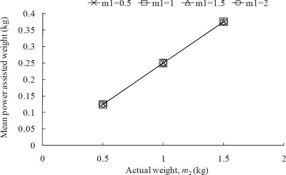
We determined mean PAWs for each size object separately after the control modification and compared them to that derived in experiment 1 for m1= 0.5 and m2=0.5. The results are shown in Fig.11. The figure shows that mean PAWs were unchanged even though m1 reduced exponentially due to the control modification. It indicates that the control modification did not adversely affect the relationships of (2).

Mean PAWs with standard deviations for large, medium and small size objects for (a) m1= 0.5, m2=0.5 (before control modification), and (b) m1= 6*e−6t+0.5, m2=0.5 (after control modification).
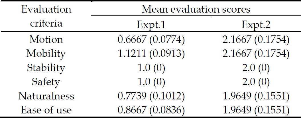
We determined the mean evaluation scores for each size PAO for experiment 2 and compared them to that for experiment 1. The results are shown in Table 6 for the medium size object. The results show that the novel control strategy of experiment 2 improved performances through reducing excessive PLFs and accelerations and the performances are quite satisfactory. Performances in experiment 1 are also more or less satisfactory though these are much inferior to that in experiment 2. Performances in experiment 1 are satisfactory because the control scheme (Fig.5) used for experiment 1 was also a novel control as weight perception was included there. Control scheme (Fig.10) used in experiment 2 is an improvement of the control scheme used for experiment 1 and hence it resulted in better performances.
Mean performances evaluation scores with standard deviations (in parentheses) for the medium size object before (expt.1) and after (expt.2) control modification
The subjects felt reduced gravity for cooperative lifting because the gravity was shared by two subjects [29]. Synchronization between two subjects in cooperative lifting might be slightly less perfect, which might affect the performances slightly [28]. We think that the satisfactory performances have been produced due to the combined effects of the appropriate values of m1 and m2, and of the application of the novel control. However, the performances may be further optimized by optimizing the values of m1 and m2 in (9) and (10) respectively.
We see in Table 6 that for experiment 2, motion and mobility got the same scores. It means that motion and mobility are interrelated and changes in one may affect the other. It means, good motion produces good mobility and vice versa. Similarly, (i) stability and safety, and (ii) naturalness and ease of use are interrelated. It means that a stable system is safe and a safe system is stable-at least for our case. Similarly, an easy to use system is natural and a natural system is easy to use.
ANOVAs showed that evaluation scores were not affected by visual object sizes. The reason may be that the subjects evaluated performances using haptic cues where visual cues of objects had no influences [27]. Variations among subjects were also found statistically insignificant (F9,18<1 for each case).
We also conducted ANOVAs (object size, subject) on peak load force, peak velocity and peak acceleration for experiments 1 and 2 separately. We found that variations between object sizes were significant (p<0.01 at each case). On the other hand, variations between subjects were not significant at each case (p>0.05 at each case). Hence, the results may be used as a general model. However, the generality may be increased if we increase the number of trials, object sizes, shapes, subjects (including end-users e.g. factory people), experiment protocols etc.
9. Discussion
9.1 Effectiveness and Accuracy of the Findings
Effectiveness of the proposed robotic system may be further enhanced by reflecting back-drivability, inertia, compliance, friction and gear effect in ball screw, and servomotor control response delay to the proposed assist control. It seems to be beneficial to estimate the subjective force of PAW and to objectify more the subjective force of human. The effectiveness and accuracy of the control may be increased by replacing the ball screw by a linear or a direct-drive motor. The servomotor was kept in velocity control mode. Another mode, torque control mode, may be tested to further justify the findings.
We used objective measurements where possible (e.g. Fig.7) though the results are somewhat based on subjective data (e.g. Fig.6). However, we argue that the subjective results are acceptable because (i) it is difficult to collect objective data in a human-robot interaction system, and (ii) this type of subjective results have already been proven reliable in many cases (e.g. [43]).
9.2 Zero-Gravity, Zero-Inertia and Zero-Load Force
It may be assumed that the PLF and perceived heaviness could be the minimum if m1=0 and m2=0 were used in (2). But, zero-gravity (m2=0) is not good for lifting objects with power-assist because humans lose some haptic information for zero-gravity, which reduces human's weight perception ability and situational awareness [34]-[36]. Zero-inertia (m1=0) is not possible because the subjects experience severe oscillations for this case [34].
The human can keep the object stand still for a while if the grip force is very high and the load force fh is very small. At this condition fh is not zero, but the displacement is almost zero. The object may have motion even if fh=0 (human does not touch the object), but it does not indicate a human-robot system and it does not provide any power assistance to the human.
9.3 Balance and Synchronization between Two Humans
Two subjects grasped the handles and lifted the objects with power assist as shown in Fig.4. We think that the resultant load force (fh) derived in (2) can be further expressed as (11), where fh1 and fh2 are the load force for subject 1 and subject 2 respectively.

We assume that fh1=fh2, and fh1 and fh2 are also synchronized. If (fh1-fh2) is high and fh1 and fh2 are not so synchronized, the system may result in instability and lack of safety [28]-[29].
9.4 Slip of the Object
There was no possibility of object-slip and the subjects did not experience any slip of the objects when doing experiments with the present setup. We think that slip prevention is related to the configuration of the real robot systems. It will need to configure the real robot system in such a way that the configuration prevents the slip of objects. Object grasping devices and object's surface conditions (friction coefficient) also contribute to slip avoidance. However, operator's training and awareness are also important to prevent the slip.
9.5 Validity of the Experiment System
We could not use a real robotic system and heavy objects, but we used a simulated system, low weights, and small objects for the following reasons: (i) we, at this stage, want to reduce the costs of developing the real system because a real system suitable for manipulating heavy objects is expensive, (ii) we want to compare the findings of this paper to that of other psychological experiment results available in literatures, and for this reason our object sizes and weights should be small because most of the psychological tests use low weights and small objects (such comparison with equal basis may produce important information that may help develop the real system in near future adjusting with human perceptions such as naturalness, best feelings etc.)[27], (iii) we want to use the preliminary findings of this paper (e.g., design ideas, assumptions, hypotheses, dynamic modeling, control programming, system characteristics reflecting human-robot interactions such as relationship between actual and perceived weights, force and motion characteristics etc.) to develop a real robot capable of manipulating heavy objects in near future. We believe that the findings we have derived will work (but magnitudes may change) for heavy and large size objects. It may be true that the findings are incomplete until we validate those using heavy objects and a real robot. But, it is also true that the findings are novel, important, useful and thus have potential application for developing real robots for manipulating heavy objects.
We put m2=0.5kg in the experiment and the human who lifts the object with the system feels 25% of m2 value, i.e. 0.125kg. It means that the human will feel only 0.125kg even when he will lift a very heavy object (such as 20kg) with the real system in industry because the load will be carried by robot system (not by human) and human's cooperation (grasping and applying forces) will control motions (displacement, velocity, acceleration) of the lifted object. Hence, it will be possible for the humans to lift heavy objects with only hands and the whole body will not need to be used.
The perceived weights, load force, motion etc. are controlled. The main factor affecting biomechanical properties is the magnitude of the load felt by human when manipulating heavy objects. In our case, the human will feel only 0.125kg even when manipulating a very heavy load with the system, which is far below the biomechanical tolerance limits (e.g., compressive, tensile, and torsional strength limits, fatigue limit) at different locations of human body [44]. We think that the dynamic psychophysical ratings for m1 and m2 in this paper will not only produce good maneuverability, stability, naturalness etc., but also satisfy operator's biomechanical criteria such as motions, hand movement and posture, joint torque, joint shear, joint stress, joint compression, joint work distribution, total mechanical work, muscular moments at joints, torque equilibrium, muscle force, forces acting on musculoskeletal system, low back stress etc. that will help avoid injuries, risks, vibrations and jerks on human body when manipulating heavy objects with the robot system. We did not measure muscle or nerve activities though we believe that these activities will be favorable due to small perceived weights. In the present case, the perceived weight is reduced and the motions are favorable, which is a clear indication of power assistance.
9.6 Validity of the Control Method
Position based impedance control and torque/force based impedance control produce good results. Results may be different for force control for reducing excessive force [37]-[38]. Our control was limited to position based impedance control. We used this control method for the following reasons/advantages (though it may have some disadvantages):
Position control compensates the effects of friction, inertia, viscosity etc. In contrast, these effects are to consider for force control, however, it is very difficult to model and calculate the friction force. Dynamic effects, nonlinear forces etc. affect system performances for force control for multi-degree of freedom system.
Ball-screw gear ratio is high and actuator force is less for position control. However, the opposite is true for the force control.
It is easy to realize the real system for the position control for high gear ratio. However, the opposite is true for the force control.
The actual system dynamics includes the thrust force of the actuator or the actuator force (fa) as given in (12). The actuator force (fa) is parallel to fh. However, the system dynamics we considered in (2) was the targeted (model) dynamics for the system.
If the difference between m and m1 is very large i.e., if (m-m1) is very big, the position control imposes very high load to the servomotor that results in instability, which is not so intensive for force control [37]-[38]. The position control method we proposed was proven effective because it produced satisfactory performances (Table 6). Position control methods have been proven effective for many similar devices [24],[30],[38–39],which justifies the validity of the proposed control method. The control in Fig.5 is not so complicated. However, there is novelty in this control that human's perception is included in the control. Again, the novel control strategy (Fig.10) was derived from it (Fig.5) that includes human features.
9.7 The Proposed Real System
We propose to use the findings as guidelines to develop power assist devices to manipulate heavy objects in industries. The configuration of the real systems should be such that operators working with the real power assist robot may lift heavy objects manually with a power-assist process or with a power assist process in cooperation with another automatic process or with their combinations. The object may be transferred with a transfer device such as a belt-conveyer for the automatic process and with a multi-DOF power-assisted cart [24], a crane [22], a hoisting machine, a suspension system [23], a specially designed device etc. for the power-assist process. The structure of the proposed system for manipulating heavy objects may be at first a 3-DOF system consisting of vertical lifting and horizontal left-right and forward-backward translational motions [40]. Then, the system may be improved to a 6-DOF system with rotational facilities.
10. Conclusions and Future Works
This paper successfully presents a model of power assist system with the design of its control for lifting objects by two humans cooperatively based on weight perception, load forces and motion features. We included weight perception in dynamics and control. We determined psychophysical relationship between actual weights and PAWs, excess in load forces, and analyzed force and motion features. We then designed, implemented and evaluated a novel control scheme based on the human characteristics, which improved the performances.
This paper presents an exclusive and complete model of weight-perception-based power-assist control for cooperative lifting of objects by two humans and proves its effectiveness. We addressed most of the power-assist control parameters (section 4), satisfied most of the requirements of power-assisted manipulation (Section 1.4), and thus attempted to overcome the limitations of the existing power assist systems (Section 1.3). Findings of this paper are novel in terms of theory, concepts, experiments, applications, performances etc., have competitive advantages over the existing counterparts, and will help develop power assist devices that may satisfy most of the required conditions in manipulating heavy objects in industries.
We will verify the results using heavy objects and real robots. Experiments in torque control mode of servomotor will be conducted to verify the results. Separated but interacting controllers may be designed and evaluated for each of the subjects. The system will be upgraded to a real multi-DOF system.