
Abstract
Synchronization of a large-scale lifting system with hydraulic actuator failures is investigated in this article. The lifting system is composed of multiple intelligent lifting subsystems with hydraulic actuators, wireless data transfer unit, and distributed controller. During the lifting process, the hydraulic actuators are possible to be malfunctioned. Once actuator failure occurs, the number of lifting points and the communication topology would change over different time intervals. This article proposes a distributed synchronization control method and adopts switching technique in analyzing the lifting synchronization. The distributed controller is designed with information received from around subsystems through wireless data transfer unit rather than with direct reference signal from the control station. On the basis of Lyapunov stability theory and switched technique, sufficient conditions that guarantee the synchronization of the lifting system with actuator failures are achieved, and synchronization errors can be reduced as small as desired. Finally, the effectiveness of proposed distributed synchronization controller is verified by numerical simulations conducted on AMESim platform. From the simulation results, it can be seen that when actuator failures occur, the synchronization error of the remaining lifting subsystems is less than 5%. The lifting synchronization error shrinks to 5% in 5.87 s when a broke-down subsystem returns to normal.
Introduction
In recent years, hydraulic lifting systems have been applied to lift massive buildings/bridges, which can maintain structural integrity.1–3 In these kinds of applications, a hydraulic lifting system usually consists of a large number of lifting subsystems. Generally, the hydraulic system with multiple actuators is controlled by a centralized control station while the hydraulic actuators are powered by a common oil pump through long pipes.4–7 It is easy to implement if the cylinders are deployed in a compact domain. Nevertheless, for large-scale hydraulic lifting systems, in which cylinders are deployed in an extensive area, the centralized control scheme is difficult to implement due to tedious long pipes and signal lines. In addition, with the development of networked distributed control technology and the advanced manufacturing technique, self-contained hydraulic systems with distributed networked controllers are much easier to be realized in practical applications.4,8,9
Therefore, a new scheme of hydraulic lifting systems is designed. In the designed lifting system, each hydraulic lifting subsystem is equipped with wireless data transfer units (DTUs) to replace traditional long signal wires and is powered by an independent pump to eliminate the oil pipes. With the wireless DTU, the lifting subsystems are able to exchange information with others. Synchronization of the hydraulic lifting subsystems is a key parameter in measuring the performance of a lifting system. One of my previous published papers 10 designs a cooperative distributed synchronization control method with information received from other lifting subsystems within its communication range. In the designed distributed controller, all the information used are acquired locally.
The previous published paper investigates the case where all the actuators work in good condition and the connections of the lifting subsystems are fixed. In this article, a more practical and complicated situation is investigated where the actuator failures are assumed to occur. In Lai et al. 11 and Lv and Wang, 12 the adaptive compensation controllers are designed for nonlinear systems with infinite number of actuator failures. The controller proposed in Lai et al. 11 is based on well-known tuning function approach and piecewise Lyapunov function analysis. It gives the relationship among the stability of closed-loop system, minimum failure time interval, and controller design parameters. In Lv and Wang, 12 the adaptive law and an intermediate control function are presented on the basis of the approximation capability of fuzzy logic systems. Then, the framework of the controller designed in Lv and Wang 12 is further simplified using radial basis function neural network (RBFNN). The main difference from this article is that the controllers in Lai et al. 11 and Lv and Wang 12 are centralized, which is not applicable for the considered large-scale lifting system with subsystems distributed in an extensive area. H Ouyang and Y Lin 13 propose a new adaptive fault-tolerant control scheme based on a switching strategy for a class of nonlinear systems with uncertain parameters and actuator failures. The authors design a set of monitoring functions as tolerance bands for supervising the behavior of the errors. The errors lying within their tolerance bands can then be compensated by the adaptive fault-tolerant control scheme since it has inherent robustness. However, it is only valid for systems with backup healthy actuators, which is not easy to satisfy. In Hashemi et al., 14 the authors design an adaptive decentralized dynamic surface control (DSC) approach for a class of large-scale systems with unknown actuator failures. Neural networks are adopted to approximate the unknown nonlinear functions, and the compensation controller is proposed based on the backstepping method and the DSC approach. However, it does not consider the change of communication topologies between the subsystems.
This article focuses on investigating the large-scale lifting systems with actuator failures, which involves information exchange between lifting subsystems. In this case, the communication topologies of the lifting subsystems dynamically change and the lifting synchronization error suffers jumps when actuator failures occur, which results in significant challenges. This article mainly focuses on solving this issue. Since the distributed controller depends on wireless communication with others, the communication topology of the subsystems partly decides the synchronization of the whole lifting system. The whole lifting system’s overall model with coupling interaction information between the subsystems is constructed on the basis of theory of large-scale complex systems.15–17 The synchronization problem of lifting systems is essentially the stability problem of synchronization error system of all the lifting subsystems. There have been some results on large-scale systems with switching topologies. However, most of the results in the literature are achieved on the basis of fixed number of subsystems.18–20
When actuator failures occur, the number of normal working lifting points decrease and the communication topology of the subsystems would change. Therefore, the existing results on large-scale systems with switching topologies or on the adaptive compensation for systems with actuator failures can provide theoretical support but are not applicable to solve the synchronization problem of lifting systems with actuator failures. It is a significant work to investigate this problem in order to attenuate the influence resulted by actuator failures. Evidently, it is a relatively challenging work to guarantee the synchronization performance with number of lifting subsystem change and the switching of communication topology of the lifting system.
Motivated by the above discussions, this article explores the synchronization problem of a large-scale intelligent lifting system with hydraulic actuator failures. The main contributions of this article are addressed as follows. First, this article proposes a new scheme of intelligent hydraulic lifting subsystem. In the proposed scheme, the hydraulic subsystem is powered by an independent pump and includes a displacement sensor, a distributed controller, and a wireless DTU. Second, a novel distributed cooperative controller is designed, and the mathematical model of the whole lifting system with variable number of lifting subsystems is established through analyzing the coupling communication topology. Then, in order to ensure the synchronization of lifting system with malfunction of hydraulic actuators, some sufficient conditions are obtained on basis of Lyapunov stability theory and switched technique with proposed average Lyapunov candidate function. Finally, simulations are conducted with AMESim, and several cases of actuator failures are considered, which prove the effectiveness of proposed distributed cooperative controller.
The notations used throughout this article are given in Table 1.
Notation.

Design and modeling of a novel intelligent lifting system
Traditionally, a hydraulic synchronous lifting system is composed of several hydraulic cylinders powered by a common pump and a centralized control workstation. All the cylinders are connected to the control server through wires, and the hydraulic oil is supplied through pipe lines from the pump station. However, in terms of lifting a massive bridge or a large-scale building, a large number of hydraulic cylinders are needed and deployed in an expansive area. Regarding this kind of applications, self-contained lifting subsystems equipped with wireless DTUs are more applicable. With the development of wireless communication technology and manufacturing technique, self-contained hydraulic systems are becoming the main development trend.
Therefore, in this article, an intelligent hydraulic lifting system architecture is designed as shown in Figure 1. The intelligent lifting subsystem is powered by an independent pump and composed of a displacement sensor, a distributed controller, a wireless DTU, and other general hydraulic components. The proposed intelligent hydraulic lifting subsystem is integrated and self-contained. Therefore, the centralized oil pump and long pipes are eliminated, which significantly decrease the oil leakage risks. In addition, the lifting subsystems are able to exchange information using the wireless DTU. Then, lifting subsystems are intelligent since they are aware of their own and neighbor’s information, with which each subsystem designs its equipped distributed controller.

Illustration of an intelligent hydraulic synchronous lifting system.
As described in Figure 1, the actuator of a hydraulic lifting subsystem is a valve-controlled cylinder. The dynamics of the cylinder can be described as


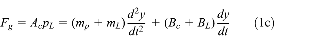
In order to organize the mathematical model in a compact form, denote
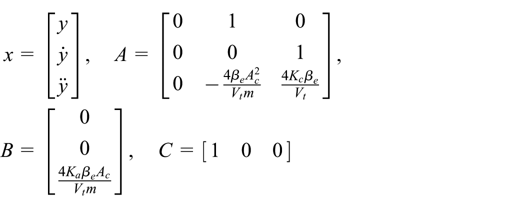
Thereafter, the mathematical model of the valve-controlled hydraulic cylinder can be further reorganized in a normal form as equation (2)
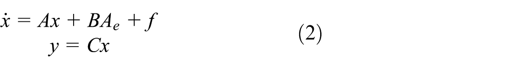
where f stands for the nonlinear part of the hydraulic lifting system, caused by friction or external disturbances.
Assumption 1
It is assumed the nonlinear function

Pratically, the direct control input is voltage or current signal and usually linearly correlates with the equivalent area

in which
Similarly, the mathematical model of ith lifting subsystem is

where
The objective of this article is to design an advanced controller to ensure the synchronization of the lifting system even with malfunction of hydraulic actuators or communication breakdown.
Cooperative controller design and synchronization problem formulation
This section proposes a new architecture of intelligent hydraulic lifting system, in which the lifting subsystems fall into two categories. As illustrated in Figure 2, the sole one that connects to the work station is called leading lifting subsystem and all the others are known as following lifting subsystems.

Illustration of a leader-following lifting system.
Each intelligent lifting subsystem is able to exchange information with others within its communication range, indicated by dashed line in Figure 2. The intersection of dashed circles implies that the corresponding lifting subsystems are connected. If the wireless DTU of intelligent hydraulic subsystem (i) is capable of communicating with another (j), the two subsystems are called neighbors and the corresponding connection weight
Specifically, in Figure 2, the ith and jth lifting subsystems are connected to the leading subsystem, hence,

Illustration of a lifting system with malfunction and change of connection.
A distributed synchronization controller for ith tracking lifting subsystem is designed with received information from neighbors

where
Let

where

in which
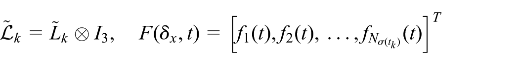
At the instant time that malfunction occurs, the number of lifting subsystems changes, implying the rank of Laplacian matrix of the communication topology is variable. Also, since the number of following lifting subsystems is not constant during the whole lifting process, the dimension of

where
Definition 1
For the lifting synchronization error system (equation (6)) with actuator failures and jump of synchronization error (equation (7)), it is said that all the lifting subsystems achieve synchronization if there exists a sufficient small scalar

Definition 2
Let

Since actuator failures occur during the lifting process, the number of normal working lifting subsystems changes. Consequently, it is no longer appropriate to measure the synchronization performance with the summation of all synchronization errors. Therefore, the average synchronization error in quadratic form is designed as Lyapunov function candidate

Synchronization analysis
Synchronization analysis of hydraulic lifting systems over time intervals
The following theorem gives sufficient conditions ensuring the stability for synchronization error system (equation (6)) over the time interval
Theorem 1
Consider the lifting synchronization error system (equation (6)) over the time interval

the lifting synchronization errors between the hydraulic lifting subsystems (equation (4)) converge over the time interval
Remark 1
For an undirected graph G, its associated Laplacian matrix
Proof
For any

In light of assumption 1, we obtain

From the above derivations, it is apparent that if

we obtain
Denote

Thus, for

Synchronization analysis of lifting systems with actuator failures
This section analyzes the synchronization of the large-scale lifting system with malfunction of the hydraulic lifting subsystems.
Theorem 2
For a large-scale lifting system with multiple hydraulic subsystems with occurrence of malfunction, the necessary conditions guaranteeing the synchronization are listed below:
Since the lifting subsystems are controlled by distributed controllers designed with information sensed from neighbouring lifting subsystems, the communication topology should be connected.
The condition (equation (10)) derived in theorem 1, guaranteeing convergence of lifting errors within time intervals, should be satisfied.
Assume that the weight of lifted heavy load is
The estimated maximum allowable malfunctioned time of each mode is supposed to satisfy

where
Proof
Without loss of generality, let

Considering inequality (equation (7)), at switching times

Iterating this inequality till
Recalling that

In light of the fact that
From condition 4, it is straightforward to obtain that
Remark 2
For a traditional lifting system without actuator failures, if the system satisfies Lyapunov stability, it will have an idea and fast convergence behavior. Since this article considers the situation where malfunction may occur in lifting subsystems, the lifting system turns to be a switched system with different dynamics over different time intervals. Specifically, as in equation (6), the Laplacian matrix of communication topology, which is denoted as
Remark 3
The first condition in theorem 2 requires the communication topology to be connected. This implies that there could not be any isolated lifting points. In terms of an isolated lifting point, it means the lifting subsystem cannot access any of the other subsystems’ information. As illustrated in Figure 4, the neighboring subsystems around the bottom right lifting subsystem are out of function. Then, the connections between the bottom right lifting subsystem and other subsystems are destroyed. The bottom right one is thus called an isolated lifting subsystem.

Illustration of an isolated lifting subsystem.
Remark 4
The proposed control scheme could be used in applications where the lifting system is composed of self-contained hydraulic actuators. The key of using the proposed scheme is that each subsystem contains a distributed controller. The computation is realized by the controllers equipped on each subsystems in a distributed way instead of a centralized control station. Thus, compared with the traditional solutions, the required computational time is possible to decrease. The work station connected to the leader is then not required to be high-grade configured. Instead, low-grade configured controllers are equipped on the lifting subsystems.
Numerical simulations
Basic simulation configurations
This section presents a large-scale hydraulic synchronous lifting system controlled by distributed controllers (equation (5)), based on which simulations are carried out. AMESim is a professional and reliable simulation tool for hydraulic systems. Therefore, in order to realistically simulate the practical situations, all the simulations are conducted on AMESim platform.
As shown in Figure 5, the established hydraulic lifting system includes one leading and six following hydraulic lifting subsystems, and the lifting subsystems are supplied by separate hydraulic pumps. The leading cylinder is directly controlled by the work station and its controller is centralized, which is distinct from the following cylinders’ distributed controllers. In real applications, to make sure the synchronization performance of lifting, the leading cylinder can be placed separately outside the heavy load.

Simulation diagram of a large-scale lifting system using AMESim.
Initially, as can be seen from the connection in Figure 5, the lifting subsystems are connected to neighbors:
AMESim configuration parameters are listed in Table.2.
Parameters used in the simulation.

From the AMESim configuration parameters, the specific values in dynamics of hydraulic subsystems are obtained

The nonlinear function is specified as
thus,
Under the above simulation configurations, the lifting heights of the intelligent hydraulic subsystems with designed distributed cooperative controllers are presented in Figure 6. From the simulation results, it is clear that with this distributed controller, the lifting system enjoys synchronization.

Lifting synchronization performance without actuator failures.
In order to show the advantages of employment of DTU, a comparison simulation without DTU is conducted. In this simulation, the lifting cylinders are supplied by a centralized pump station with long pipes and the valves are controlled by long wires connected to a centralized controller. The result is shown in Figure 7. As can be clearly seen from Figure 7, at initial and switching times, the synchronization errors of lifting heights of the subsystems are relatively high due to the time delays caused by long pipes and wires, which are avoided in the proposed scheme using DTU.

Lifting synchronization performance without DTU.
Remark 5
It should be noted that, normally, the time delay of wires is smaller than the wireless devices. However, for the large-scale lifting system with numerous hydraulic subsystems deploying in an extensive area, the system is traditionally controlled in a centralized way. The subsystems communicate directly with the central control station, and then the wires would be very long and suffer from large time delays. With the proposed DTU scheme, the subsystems only communicate with others within a certain range in a distributed way, which avoids long-distance communications. Therefore, the synchronization with DTU is better than the synchronization without DTU.
Simulations with actuator failures
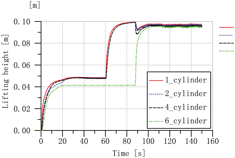
This section carries out simulations with actuator failures. Initially, the number of lifting subsystems is
Figure 8 illustrates the situation where lifting subsystem 5 goes out of order at 30 s, and Figure 9 presents the synchronization performance of the situation where malfunction occurs in lifting subsystem 3 at 70s. From the simulation results, it is clear that when malfunction occurs, the lifting synchronization is affected. However, the synchronization errors are still within a certain small range. Specifically, when failure occurs in lifting subsystem 5, the synchronization error of the remaining lifting subsystems is within 5% as shown in Figure 8. When failure occurs in lifting subsystem 3, the synchronization error of the remaining lifting subsystems is within 3% as shown in Figure 9.

Synchronization performance with malfunction of subsystem 5 at 30 s.

Synchronization performance with malfunction of subsystem 3 at 70 s.
Next, simulations are carried out with two actuator failures and a lifting subsystem is thus isolated. In Figure 10, it is assumed that lifting subsystem 5 is out of order at 30 s and lifting subsystem 3 is out of order at 70 s. From 70 s, lifting subsystem 6 cannot receive information from others anymore and then is isolated. Therefore, the output of sixth cylinder stays constant from the moment isolated from others, while the synchronization error of the remaining lifting subsystems is within 2% as shown in Figure 10.

Synchronization performance with malfunction of subsystem 5 at 30 s and malfunction of subsystem 3 at 70 s.
In Figure 11, malfunction occurs in lifting subsystem 3 at 20 s and is back to normal at 90 s. As can be seen from the simulation result, when the broke-down subsystem returns to normal, the lifting synchronization error shrinks to 5% in 5.87 s.
Synchronization performance with broke-down subsystem back to normal.
From the above simulation results, it can be seen that the lifting system achieves synchronization and is robust with proposed distributed cooperative controller when actuator failure occurs.
Conclusion
This article investigates the synchronization problem of a class of large-scale lifting systems with actuator failures. A novel scheme for designing intelligent lifting subsystems is proposed, which includes wireless DTU and self-contained hydraulic lifting subsystems. The distributed cooperative controller is designed based on received information from others within its communication range. The lifting synchronization is guaranteed even there exist actuator failures during the lifting process since the subsystems cooperate with each other through the designed controller. It can be concluded that the lifting synchronization error is less than 5% when actuator failures occur in the whole lifting process with the proposed cooperative control scheme.
Footnotes
Handling Editor: Zhaojie Ju
Declaration of conflicting interests
The author(s) declared no potential conflicts of interest with respect to the research, authorship, and/or publication of this article.
Funding
The author(s) disclosed receipt of the following financial support for the research, authorship, and/or publication of this article: This work was supported by the Fundamental Research Funds for the Central Universities (grant nos 2017JBM051 and 2018RC011) and the International Science & Technology Cooperation Program of China (no. 2012DFG71490).