
Abstract
In this research, we describe an actuation and control system designed for geared electromagnetic motors, which is characterized by its simple implementation, fast response to external input loads, reliable human-machine interaction features, no need for previous set-up or calibration from user to user and high portability due to the reduction of weight and space used. By the implementation of the proposed system, an electromagnetic motor can become a multitasking, wearable actuation system capable of: detecting the user's intentions regarding motion, tracking the limbs with minimal force interaction within a wide bandwidth and also providing controllable assistance and resistance forces to the user's movements, without the use of any biological signal. Validation of the proposed approach is shown by the construction of a powered orthosis for the knee, used to test the system's performance under real human motion conditions. The proposed system was tested on one healthy subject by measuring electromyographic levels both with and without the orthosis, under controlled flexion and extension cycles. Experimental results demonstrate the effectiveness of the proposed approach in detecting the user's intentions regarding motion, reducing and increasing muscular activity when configured for assistance and resistance, respectively, and also increasing the transparency of the actuation system when perfect tracking of the limbs is needed.
Keywords
1. Introduction
Actuation and control of ‘assist-as-needed’ robotic devices used in rehabilitation therapies and geriatrics must offer compliant and reliable interaction with the user, make the actuation mechanism as transparent as possible and provide controllable assistance and support in order to achieve the functional goal of the device. A novel actuation and control system designed to achieve full backdrivability in geared electromagnetic motors is proposed for use in wearable robotics applications, where large controllable torques and high motion speeds are required to support and assist the user's movements ‘as-needed’, and also to achieve perfect tracking of the limbs when no hindering of the movements is desired. One of the potential applications of the proposed approach is the treatment of gait abnormalities such as Hemiplegic Gait, Stomping Gait, Diplegic Gait, Neuropathic Gait and Stroke Gait, which are characterized by muscular weakness and foot drop. These disorders could be reversed by the correct alternation of Assistive-Resistive therapies on the affected limb [1], in combination with the use of non-invasive motion-decoding methods for people without mobility, such as Electroencephalography [2]. Also, people suffering walking difficulties due to ageing could benefit from the proposed system by assisting and supporting their moves when walking. Moreover, physical therapists have found a promising tool in wearable ‘assist-as-needed’ robots, which could make post-surgery rehabilitation more effective for patients and less demanding for therapists, reducing the time spent in physical recovery for the patient.
Most powered exoskeletons and active orthoses use geared electromagnetic motors. The backdrivability of geared drives is poor due to friction. While it is common practice to use velocity measurements to compensate for kinetic friction, breakaway friction usually cannot be compensated for without the use of an additional force sensor that directly measures the interaction forces between the human and the robot. Unfortunately, improving backdrivability in a wearable actuator is still an open problem. Previous studies have proposed the use of a feed-forward control strategy to overcome the breakaway friction of the actuator [3]. Also, a model-based control scheme to recover the backdrivability of a Rotary Series Elastic Actuators (RSEA) is proposed in [4].
Concerning human-robot interaction, compliant adaptability between the two systems is required, and it can be achieved via two methods: passive and active compliance [5]. The first approach uses a passive elastic element to store and release the mechanical energy, such as the torsional spring used in the RSEA. This is not the case for actuators with active compliance, where the controller of a stiff actuator mimics the behaviour of the elastic element. Most of the assist-as-needed devices use passive compliant actuators, such as the LOwer-extremity Powered ExoSkeleton (LOPES) [6], which is powered by Series Elastic Actuators (SEA). The Mechanically Adjustable Compliance and Controllable Equilibrium Position Actuator, or MACCEPA, is also a passive compliant actuator that has been chosen to actuate the step rehabilitation robot ALTACRO [7]. Also presented in [8] is an actuator with mechanically adjustable stiffness (AwAS) that can independently control equilibrium position and stiffness by using servomotors and springs. Passive elastic elements have several drawbacks such as limited stiffness, limited bandwidth and changes to their mechanical properties due to continuous wear, among other factors [1]. Moreover, demonstrated in [10] is the superior performance (fidelity and bandwidth) of an active-compliant actuator while tracking static forces and the reduction of the mechanical impedance offered by the actuator when an external input load is applied.
Compliant interaction of wearable robots with stiff actuators is achieved under two basic paradigms: user in charge and robot in charge. The difference between paradigms resides in who leads and who follows the motion. In order to provide a robot with the capability of synchronously following and leading the motions of human limbs, different control strategies have been implemented that use estimation/feedback of the actuator variables such as force-torque, position or a combination of the two. Force, impedance and admittance control are common strategies used to generate compliant behaviour in stiff actuators [6]. Impedance control achieves bi-directional interaction between the user and robot by measuring position and displaying force, while admittance control measures force and displays position; therefore, these strategies are considered to be ones for constrained motion rather than a concrete control scheme. The HAL exoskeleton [9] is one of the most well-known active-compliant assistive robots, which implements a viscoelastic model of the human-machine interaction, and reads biological information from the user (EMG activity), in order to activate and command the device. The major drawbacks of HAL reside in the control system, which is limited in bandwidth and requires a previous calibration of the biological EMG signals for each user to use it properly. Also, the system's performance depends fully on the precision of the model parameter's estimation and how well the biological information is gathered from the electrodes placed on the skin's surface. Some other approaches to lower-limb exoskeletons and active-compliant actuation systems are presented in [11].
A complete summary of the experimental results obtained by active orthoses and lower-limb exoskeletons can be found in [12], which states that ‘one of the general goals in designing an assistive lower-limb exoskeleton should be reducing the metabolic cost of walking’. Independent of other functional goals, such as correction of the gait pattern or improving the ambulatory capabilities of the user, an exoskeleton should at least avoid increasing the metabolic costs and muscular activity with respect to unassisted motion. However, recent research shows that very few of the existing exoskeleton systems have demonstrated any capability to reduce metabolic consumption [13–15]. In some cases, the device has actually produced the opposite effect [16], due to the constraints of using passive elements in the actuation systems and the poor performance of complex model-based control algorithms.
In brief, the novelty of our work resides in the mechanical and sensorial configuration to measure human-robot interaction forces inside the actuation system (which means that no sensors are attached directly to the user and, thus, no previous calibration is required). Also, the control scheme that is designed to achieve minimal force interaction between the user and robot, force tracking in both rotational directions and detection of the user's intentions regarding motion. Further details of our approach will be given in the following sections. Section 2 explains the methodology used to achieve tracking, controllable assistance/resistance and identification of the user's intentions. Section 3 describes the design and materials used to construct the actuator and the powered knee orthosis. The experimental set to validate the control and actuation system is also described in this section. Results are presented in Section 4 followed by the discussion in Section 5.
2. Methods
2.1. Actuation Mechanism
The proposed actuation system was implemented on a commercial, brushed DC motor with a built-in gearbox. Elements of the prototype were machined on aluminium in order to reduce weight and space. The mechanism comprises two assembled elements, one attached to the motor shaft and the other attached to the user's limb, with two bearings that allows free rotation to the user link and two Force Sensing Resistors (FSR), as shown in Figure 1. The total weight of the mechanism is 0.3 kg and its adaptation to a given geared motor depends on the output shaft's characteristics, such as diameter, length and orientation.

Elements of the actuation system placed on a geared DC Motor a) lateral view, b) frontal view
The mechanical principle involved in the actuation system works so that the interactive forces fL and fR between the user and the actuator can be measured by both force sensors placed inside the joint (
Force Sensing Resistors by the FlexiForce brand were used to measure interaction forces. This kind of sensor was selected due to its high linearity (±5%) and repeatability (±2.5%), and low hysteresis (4.5%), noise, power consumption and cost.
2.2. Dual Zero Force Controller
The key issue in human-robot interaction is the capacity of the two systems for mutual adaptation. A zero interaction force controller is the simplest strategy when the target impedance of a wearable robot is calculated, in order to minimize the interaction force between the human and exoskeleton [17].
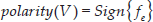
Figure 2 shows a block diagram representation of the dual zero force controller designed to achieve force tracking with minimal force interaction in both rotational directions. The amount of voltage and its polarity delivered to the DC motor by the controller are calculated based on the deviation between the FSR signals. By defining this deviation as fe = fL - fR, the control law can be expressed as follows:
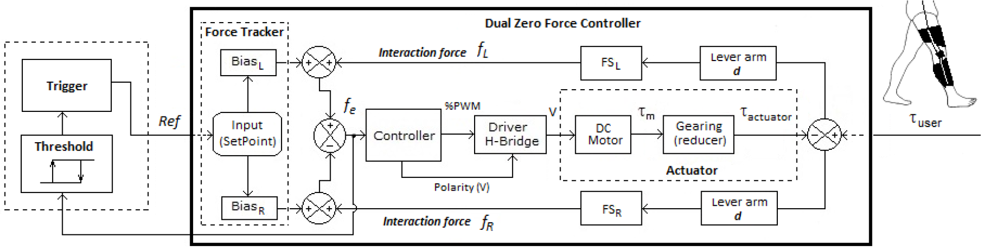
Block diagram of the proposed control system to perform detection of the user's intent, tracking and assistance/resistance-as-needed of human limbs with a geared DC motor
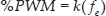
where %PWM is the duty cycle of a Pulse-width Modulation signal, k is a gain constant and fL and fR are the signals from the
2.3. Tracking User Movements
The dual zero force controller is designed to reduce the deviation fe. By reducing the interactive forces to zero, we ensure that the actuator is perfectly compensating for the input torque applied by the user and, thus, is achieving perfect tracking of the movements with minimal force interaction. The effectiveness of reducing this deviation rapidly is linked to three main aspects: the execution rate of the control algorithm, the maximum output speed of the geared DC motor and the value assigned to the gain constant k. If we seek to achieve the tracking of lower limbs, which can reach a motion frequency of 4 Hz when walking [18], then the actuator should display a rotational full-voltage speed of
2.4. Controllable Assistance and Resistance Force
The proposed control algorithm is able to balance forces applied by the user when trying to command the robotic device to move any rotational direction, producing a soft and accurate tracking of the limb with minimal force interaction. Thus, the actuation system is made active-backdrivable, even if the reducer mechanism is non-backdrivable (i.e., a worm-gear reducer). If the controller is able at any time to reduce sufficiently the difference between the two FSR signals (fL and fR from Figure 2), then it is possible to implement a force control scheme in which human-robot interaction forces can be controlled. This feature is achieved by the

When either of the two unbalancing variables is other than zero, then the controller will tend to rebalance the system by generating more output voltage to the DC motor until the error fe is returned to zero. This approach allows the actuator to provide any interactive force in both rotational directions, in the full range of the maximum force that FSRs can measure.
2.5. Detection of the User Intent
According to the control scheme shown in Figure 2, on the left-hand side there is an input channel receiving the human-robot interactive force to be provided by the actuation system. The magnitude and direction of the force reference (Ref) could be masked on a single byte for practicality when using an 8-bit micro-controller (0 = maximum CW interaction force, 128 = minimal interaction force and 255 = maximum CCW interaction force). In terms of user perception, the interaction force can be either assistive, resistive or even zero, depending on the direction in which the limb is moving. In order to synchronize the robot with the user for assisting, resisting or tracking the limb, a method of detecting the user's intent is required. The most common methods used in detecting the intentions of human motion are based on the measurement of Electroencephalography (EEG), Electromyography (EMG), Plantar Pressure Signals (PPS) and Joint Angular Position, which require the direct attachment of sensors to the human body and a previous calibration process from user to user. In this work, an alternative method is proposed, which uses the interaction forces inside the actuation system in order to detect the intention of moving the actuated joint, and consists in comparing in every sampling cycle the deviation fe with a given threshold
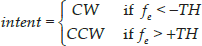
By using the sign of the deviation fe, it is possible to determine the direction of the movement attempt (CW or CCW). Therefore, the corresponding mode (assistance, resistance or tracking) can be triggered depending on the user's needs. A threshold value is assigned to the variable
3. Experimental Evaluation
A powered knee orthosis was built to test the proposed actuation and control system performance under real conditions of human motion. Construction was achieved by using lightweight and stress-strain resistant materials. Thigh and calf frames were built with aluminium to provide rigidity while the coverings were made with a combination of fibreglass, plastic and foam. A telescopic mechanism was implemented in both thigh and calf to adjust the user's leg length, in order to align the orthosis with the knee's rotational axis. A hip connector holds the orthosis in place with an elastic band and is used to keep the orthosis in the same place, and to prevent it from sliding down due to gravity and inertial forces. Finally, four Velcro straps were used to attach the orthosis to the thigh and calf, as shown in Figure 3.

Customized active orthosis placed on the leg of a healthy subject
To evaluate the new methodology for assisting, resisting, tracking and detecting the user's movements, 10 different experiments as shown in Figure 4 were carried out, measuring interactive forces (fL and fR), the knee's angular position and EMG activity of the two principal muscles in charge of performing the knee's flexion (Biceps Femoris) and extension (Rectus Femoris) [19]. The test condition's order is also shown via numbers in Figure 4. A healthy 30-year-old male subject (1.87 metres and 80 kilograms) with full mobility was selected for the experiment.
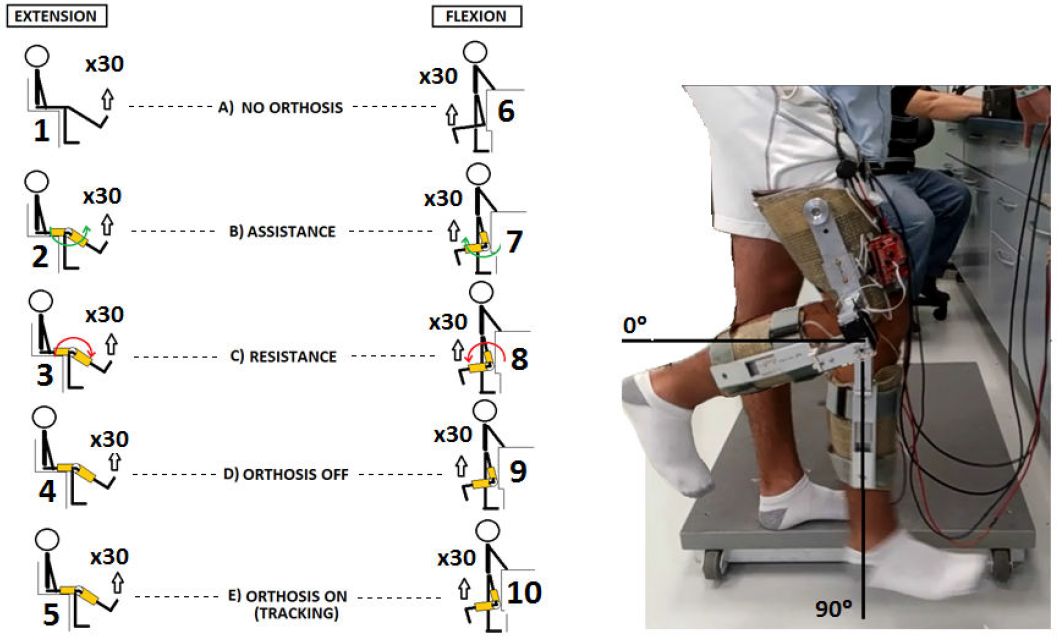
(Left) Experimental set for the flexion and extension of the knee. (Right) Test subject wearing the active orthosis.
For each of the aforementioned experimental conditions, data from 30 flexion-extension cycles were recorded, with one cycle every 1.5 seconds (0.6 seconds to achieve each semi-cycle, approximately). This is the maximum controlled speed of the healthy subject executing one cycle and is, according to the gait analysis presented in [18], considered to be a fast voluntary movement for an average person when walking (>2 Hz). A minimum rest period of one minute preceded each new test condition. To ensure consistency of positioning and timing during each test, the subject was visually assisted by projecting onto a screen the real-time variables (knee joint position and EMG activity), in order to guarantee that initial and end angles were reached. Also, a virtual green LED was implemented and projected, which was programmed to blink at variable intervals to synchronize the subject's motion when performing flexion and extension cycles. With this technique, it was possible to obtain the maximum motion frequency at which the subject could perform controlled voluntary movements (1.5 seconds per flexion-extension cycle). A maximum force reference of 100 pounds (445 N) was programmed for the assistive and resistive experiments. EMG activity was acquired using the Biopac Mp35 measurement kit with the following configuration: gain = 1000, bandpass filter = 5-1000 Hz and sampling frequency = 500 samples/s. Channel 1 and Channel 2 electrodes were placed at the middle of the Biceps Femoris and Rectus Femoris muscles, respectively, while the reference electrode was placed on the tibia area. Prior to the electrodes' attachment, the areas were cleaned with an abrasive gel in order to reduce electrical impedance. The maximum voluntary contraction (MVC) values of each muscle were obtained at the beginning of the experiment. In order to obtain the Biceps Femoris's MVC, the subject was asked to flex the knee joint while in a standing position, while manual pressure was applied by one of the researchers at 45 degrees (the full flexion midpoint). In the same way, the Rectus Femoris's MVC was obtained while the subject was in a sitting position and trying to overcome the resistance offered by a hand while extending the knee joint at 45 degrees (the full extension midpoint). Each contraction was performed for 5 s with a gradual increase of strength over 1 s, a sustained maximum for 3 s and a gradual release over the final second. Three repetitions of each test were performed, with a minimum rest interval of 30 s between repetitions. A minimum rest period of 2 minutes preceded each new test position. The maximum value of the resulting EMG envelope was determined, and this was averaged across the trials for each test to obtain the MVC value for each muscle. MVC values of both muscles were used to normalize the collected EMG data from the experimental set in Figure 4.
4. Results
The results obtained from the i=10 experiments as described in the previous section are given in terms of the average Area Under the Curve (AUC) of EMG activity from the N=30 flexion/extension cycles performed in each experiment, as expressed in (5) and (6).


In which μi is the average AUC of the N=30 flexion/extension cycles,
Figure 5 shows the first and last five flexion and extension cycles for a better appreciation of the plots. For each experiment, the angular position of the knee and the normalized EMG activity of the Rectus Femoris and Biceps Femoris muscles were plotted. The linear envelope of the EMG signals low-pass filtered at 5 Hz is also shown.
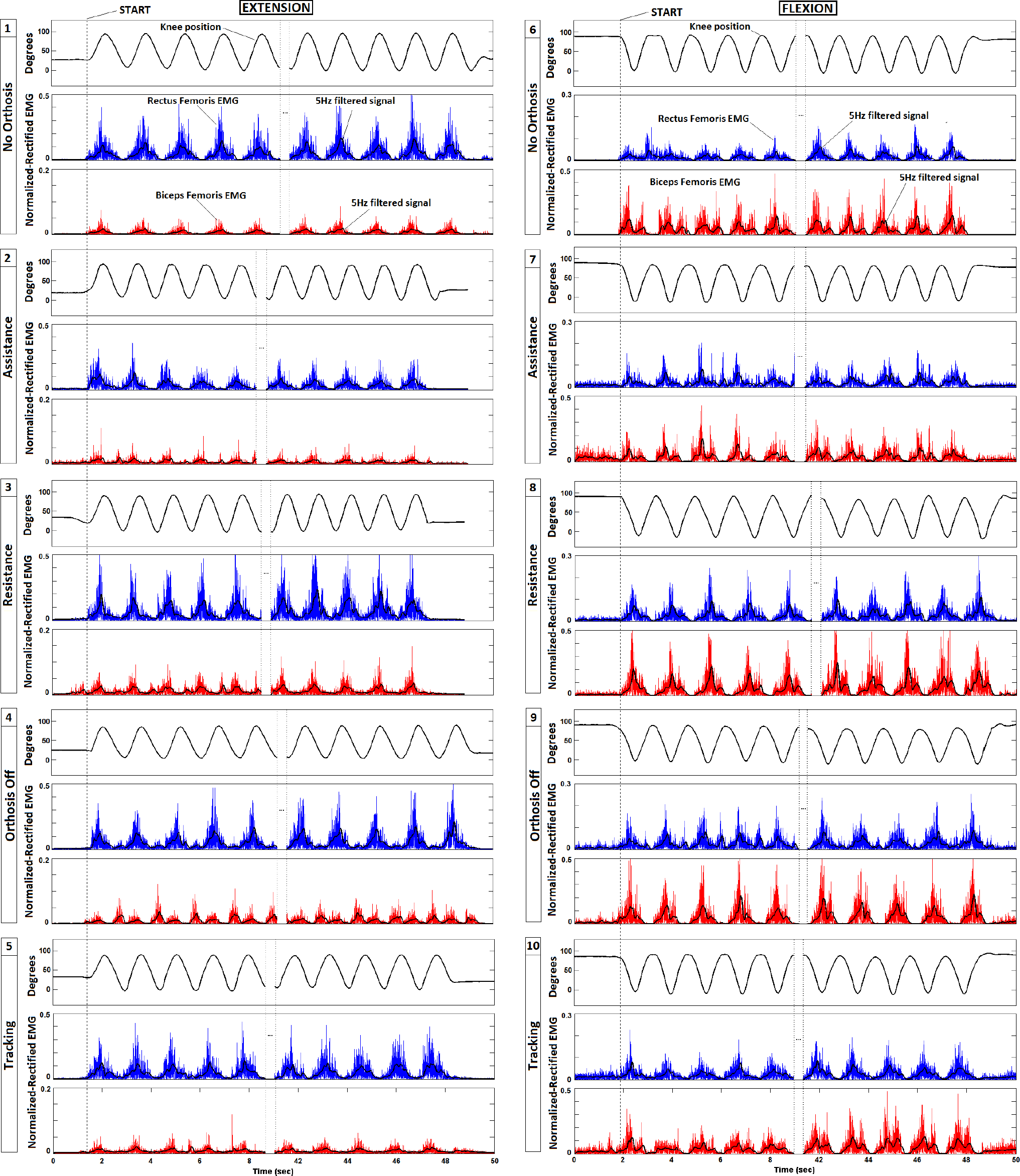
Plots of the knee's position, normalized EMG activity of the Biceps Femoris (red) and the Rectus Femoris (blue), obtained from the experimental set of Figure 4
4.1. Data Analysis and Validation
A. Data Showed Normal Distributions
We used the Q-Q plots method to validate the data's normality. This method consisted in obtaining the inverse-expected values of a Standard Normal Distributed Function (SNDF) using the mean and standard deviation from a group of samples. The validation is achieved when the inverse-expected values from the SNDF are compared with the real values of the samples. The similarity between the expected and real data from the experiments plotted in Figure 5 resulted in 98.5 ±0.27%, which allowed us to consider all the experimental EMG data as normally distributed.
B. Statistical Hypothesis Test
To determine if the data sets were significantly different from each other, we used the t-student test. The test was applied to the averages μi of the No-Orthosis condition set against each of the other experimental conditions, in order to test the effect of each condition on muscular activity when flexing and extending the knee joint. Results of the T-test with a significance of α =0.005 are summarized in Table 1.
T-test for the experimental sets of Figure 5 using a significance of α=0.005

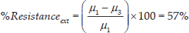
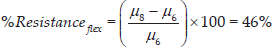
C. Assistance and Resistance Results
According to the T-test results, the amount of assistance/resistance provided by the active orthosis can be expressed as the percentage reduction/increase of the average muscular activity in the following equations:


These results can be observed in Figures 6 and 7, which shows the data set of Assistance (green squares) with the lowest muscular activity, the data set of Resistance (red triangles) with the highest muscular activity and the Tracking data set (purple crosses) in the middle of the aforementioned experiments for both flexion and extension exercises. Figures 6 and 7 also shows the linear regression of Assistance-Tracking-Resistance data, from which can be observed the linear effect of the actuation-control system on the user's muscular activity when configured to assist-track-resist the user's movements. Linear approximation (plotted in dashed black lines) of the flexion and extension data can be used to predict the effect that the actuation system will produce on the user's muscles if a faster and more powerful geared motor is used under the active-backdrivability control scheme.

(Top) EMG data sets of the Biceps Femoris, (bottom) Rectus Femoris vs. Biceps Femoris EMG activity from flexion exercises

(Top) EMG data sets of the Rectus Femoris, (bottom) Rectus Femoris vs. Biceps Femoris EMG activity from extension exercises
D. Tracking the User's Movement Results
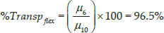
One important aspect to consider when evaluating the performance of an assist-as-needed wearable robot consists in determining how transparent the device is for the user when it is configured to track movements. Then, the effectiveness of the proposed control algorithm when tracking the user's movements can be measured by the discrepancy between the EMG levels without the orthosis and those while wearing the orthosis configured for tracking, as expressed in the following equation:

E. Detection of the User's Intent Results
Figures 8 and 9 show the assistance and resistance experiments, respectively. Plots of the knee position, force deviation fe, actuator torque (
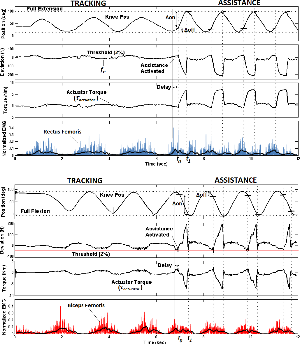
Identification of the user's intent using the force threshold approach for Extension Assistance (top) and Flexion Assistance (bottom)
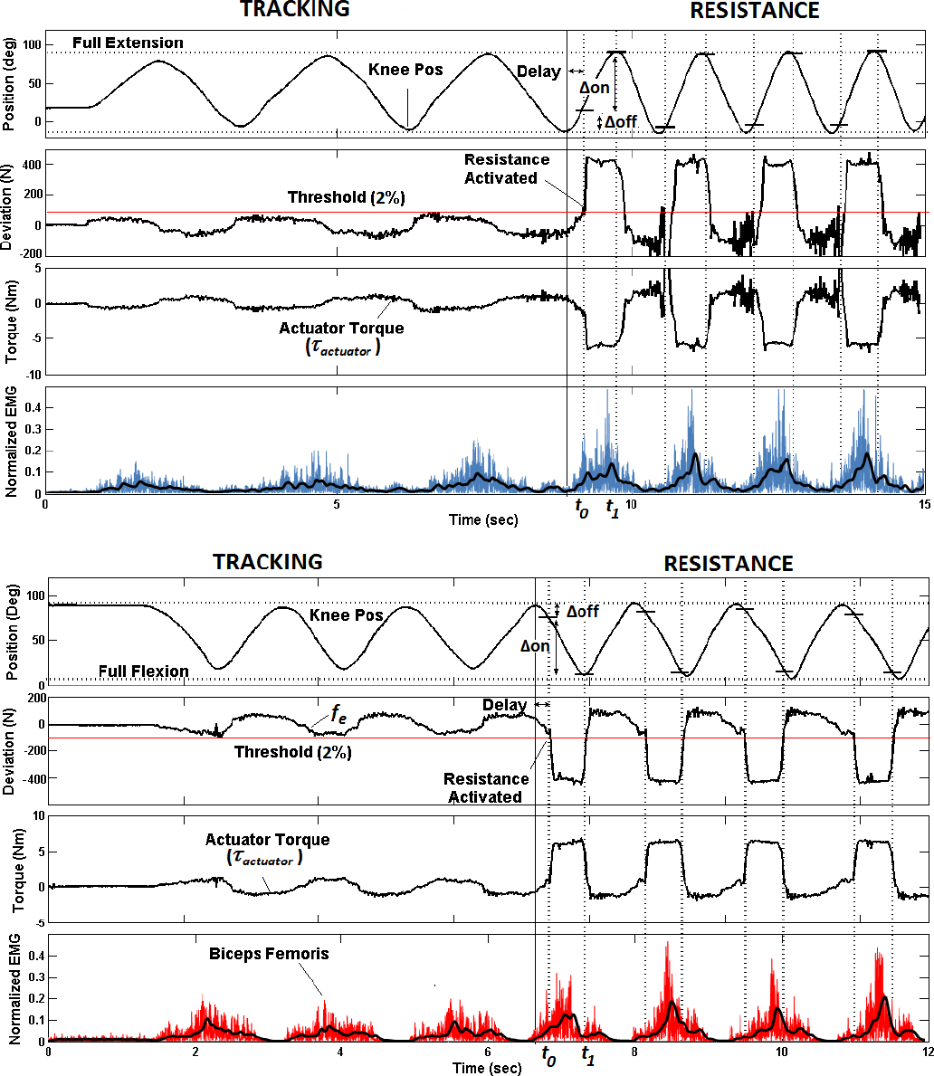
Identification of the user's intent using the Force Threshold approach for Extension Resistance (top) and Flexion Resistance (bottom)
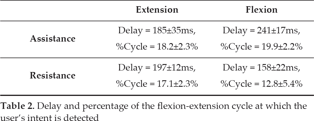
Delay and percentage of the flexion-extension cycle at which the user's intent is detected
5. Discussion
The transparency of a wearable robot is an effect of its inherent output mechanical impedance when configured to
With the use of a 6 Nm, 64 rpm geared DC-motor and 100-pound force sensors, the proposed control system achieved real assistance and resistance of fast human movements, given in terms of muscular activity's reduction (38% for extension and 20% for flexion) and muscular activity increments (57% for extension and 46% for flexion), respectively. These results prove the effectiveness of the control scheme for tracking forces in both rotational directions with no alteration of the natural motion's trajectory. On the one hand, the discrepancy between the assistance percentage of extension and flexion is attributed to an asymmetry in the muscular activity of the opposite muscles, as shown in the linear approximation slopes of Figures 6 and 7. On the other hand, the difference between the assistance and resistance results is attributed to the total torque provided by the actuation system to the movement, since for the resistance experiments, the maximum resisting-torque is displayed at the beginning of the flexion-extension cycles, in contrast with the assistance experiments in which the maximum assisting-torque is displayed at the end of the cycles, as shown in Figures 9 and 8, respectively.
Finally, referring to the results obtained with the methodology proposed in order to identify the user's intent, some important aspects deserve attention, such as the simplicity of implementation, the accuracy achieved and the detection delay. Since the identification method consists in comparing the deviation fe with a given threshold, then the required processing resources are low and the accuracy of identification obtained is 100%, which provides the high reliability of the system. Also, the identification period of our approach is acceptable (195ms average @17% of the cycle) when compared with online-decoding methods using other biological signals such as EEG (93.91±6.09% accuracy and an average detection delay of 271-310 ms) [20] or EMG (68%-88% accuracy and an average detection delay of 200 ms) [21]. However, the constraint of having a mobility degree from the user in order to achieve the detection of the intent remains.
In conclusion, the proposed actuation and control system demonstrated its capability of tracking forces in the motion-frequency range of a healthy subject for fast movements, and in providing controlled assistance and resistance to the user's limb. The control algorithm also achieved a considerable increment of the robotic device's transparency when tracking the user's limb with minimal force interaction. Experimental results show the potential application of an active-backdrivability scheme in assist-as-needed rehabilitation robots and geriatric devices due to the following characteristics: portability is increased due to the space and weight reduction (since no elastic elements such as springs are required), long service life and high reliability is achieved by the reduction of mechanical elements that are prone to wear and, finally, the algorithm's simplicity, which offers a high performance and accurate multitask-wearable system at a low implementation cost and with a low level of processing resources.
Footnotes
6. Acknowledgements
This research was partially supported by Laboratorio de Rob otica del area Noreste y Centro de Mexico-CONACyT, Tecnologico de Monterrey Robotics/Biomecathronics Research Group, Tec-Bionics Start up and the Non-Invasive Brain Machine Interface Systems Lab at the University of Houston. This article is a revised and expanded version of a paper entitled Novel Compliant Actuator for Wearable Robotics Applications, presented at the 35th Annual International Conference of the IEEE EMBS Osaka, Japan, 3-7 July, 2013.