
Abstract
Weight-perception-based fixed admittance control algorithm and variable admittance control algorithm are proposed for unimanual and bimanual lifting of objects with a power assist robotic system. To include weight perception in controls, the mass parameter for the inertial force is hypothesized as different from that for the gravitational force in the dynamics model for lifting objects with the system. For the bimanual lift, two alternative approaches of force sensor arrangements are considered: a common force sensor and two separate force sensors between object and human hands. Computational models for power assistance, excess in load forces, and manipulation efficiency and precision are derived. The fixed admittance control algorithm is evaluated in a 1-degree-of-freedom power assist robotic system. Results show that inclusion of weight perception in controls produce satisfactory performance in terms of power assistance, system kinematics and kinetics, human–robot interactions, and manipulation efficiency and precision. The fixed admittance control algorithm is then augmented to variable admittance control algorithm as a tool of active compliance to vary the admittance with inertia instead of with gravity. The evaluation shows further improvement in the performance for the variable admittance control algorithm. The evaluation also shows that bimanual lifts outperform unimanual lifts and bimanual lifts with separate force sensors outperform bimanual lifts with a common force sensor. Then, the results are proposed to develop power assist robotic systems for handling heavy objects in industries.
Keywords
Introduction
Workers in industries such as manufacturing and assembly, mining, construction, logistics, transport, rescue and disaster operations, military, timber, and so on, frequently manipulate heavy objects. However, manual manipulation is tedious, it reduces efficiency and causes back pains, injuries, and musculoskeletal disorders. 1 On the contrary, autonomous manipulation does not provide expected flexibility. 2 We argue that human–robot systems such as power assist robotic systems (PARSs) may be perfectly used for heavy object manipulation where the combination of mechanical strength of a robot and flexibility of a human may make the system far better than the individual robot or the human. 3 The PARSs possess advantages over conventional manipulation devices such as the human has direct interaction with the object, which improves haptic engagement, intuitiveness, motion control, accuracy, ease of use, robustness, and efficiency. Again, the PARSs can be operated with less experiences and skills. 4
A good number of PARSs have already been proposed for handling objects. 3 –16 Kazerooni 3 introduced the basic principles of power and information sharing for a PARS. Niinuma et al. 4 presented a power-assisted overhead crane and compared its effectiveness to that of the conventional manipulation. Doi et al. 5 presented a pneumatic hand crane type PARS. Hara proposed smooth switching from power-assisted control to automatic transfer control for horizontal manipulation of objects. 6 Yagi et al. proposed upper-limb power-assist control using a pneumatic actuator for agricultural load lifting. 7 Dimeas et al. proposed admittance neuro-control of a PARS for lifting objects. 8 Hara and Sankai developed the “hybrid assistive limb” to assist human carry objects. 9 In the studies by Gosselin et al. 10 and Lecours et al., 11 an assistive robot was proposed for handling large payloads and the safety was provided through the mechanism. In the study by Lamy et al., 12 a PARS was presented that amplified the actuation force when a knife was co-manipulated through a heavy ham in collaboration with a human. There are also a few power amplification and assistive robots that are already in applications in industries such as the “power loader light,” 13 Cobot, 14 and so on. Various industrial assist devices (IADs) for object manipulation are reviewed in the study by Colgate et al. 15 Olivier et al. 16 introduced the “Cobomanip”—an IAD for handling loads in industries, and so forth. As introduced earlier, it seems to be true that the state-of-the-art power assist technologies for object manipulation have achieved significant advancements, but the present PARSs have a few fundamental limitations as explained below.
First, the amount of power assistance is not well defined, which may specify the amount of power the system may assist to the user or the amount of force it may amplify for the user. The amount of assistance may vary for object weight, working conditions, user’s need, and feelings. However, a computational method to specify such amount that may help fit with task requirements and user’s expectation has not been introduced yet. A few systems use predefined assist ratio, 7,9 or force amplification ratio, 12 but their basis has not been explained and their modulation with human’s feelings has not been justified.
Second, the human perceives reduced heaviness when lifting an object with a PARS, that is, the haptically perceived weight is smaller than the visually perceived weight. 3 However, the human usually feed-forwardly estimates the vertical lifting force (load force) required to lift the object with the PARS depending on the visually perceived weight, 17 and thus the applied load force determined based on the pre-estimated visual weight becomes larger than the actually required load force, which may cause unwanted motion (acceleration), lack of safety and stability, accidents, and poor human–robot interactions (HRI), and manipulation performance (efficiency and precision). 3,18 We think that weight perception should be reflected in the controls of the PARSs to mitigate this problem. However, the state-of-the-art PARSs never consider weight illusion in controls. A few systems attempted to resolve this problem through gravity compensation. 4,8,15 However, zero gravity removes haptic feelings partly that is not good for haptic manipulation of objects between human and robot. 19 Again, for gravity compensation, the systems need to know the value of object mass. A few systems used object mass in the dynamics. 6,10,11 However, the basis of the nomination of the mass value was not justified, which may not be suitable for desired HRI. A few systems used tentative feed-forward models of load force with the notion that the load force would be corrected after the user had gained experiences. 5,6 We think that estimation of load force is a perceptual issue and it should be addressed psychophysically, 17,18 which is not considered yet.
Third, selection of control methods for manipulating objects with a PARS is still challenging. 20 For handling heavy objects, large inertia, friction, and dynamic effects are expected, which may be compensated and positional accuracy may be provided by admittance controls. 8 Admittance parameters (virtual mass, damping, and stiffness) may affect HRI and manipulation performance. For example, for large admittance parameters, large human force may be required to move the object, human may feel more heaviness (more potential fatigue), movement may be slow (low acceleration), but precise (fine, smooth) manipulation may be achieved. On the other hand, low admittance parameters may require less human force (low fatigue) to accelerate the manipulation, but precision may reduce as the robot is more reactive. These are the disadvantages of the fixed admittance control algorithm (FACA), which has given birth to the variable admittance control algorithm (VACA). 10 As an example of VACA, the virtual mass was varied to adjust the acceleration and precision for power-assisted manipulation. 10 However, the effects of the excessive accelerations that arise from human’s error in force programming due to the difference between visual and haptic weight perception were not mitigated. Again, changes in virtual mass change the acceleration and also alter human’s haptic (kinesthetic, tactile) perceptions, which may not provide appropriate HRI. We believe that novel VACA is necessary to modulate the kinematics and haptic perceptions separately for better HRI and performance. However, such initiative has not been taken yet except a few preliminary works. 18,19
Fourth, in industries, workers manipulate objects using one hand (unimanual) or both hands (bimanual) considering object’s physical features (mass, size, shape, and surfaces) and task requirements (efficiency and precision). 18,21 Distinctions in grasp configuration (unimanual or bimanual) may affect system kinematics and kinetics, power assistance, HRI and manipulation performance, 18 and manpower requirement, 4 but such distinctions have not been investigated and reflected in the controls of PARSs yet. 4,7 Again, the arrangement of force sensors for bimanual lifts (common force sensor or separate force sensors between object and human hands) may influence HRI and performance as such arrangements may affect human–robot haptic engagement, intuitiveness, human intention, and information sharing, 3 which may also affect the synchronization of controllers for the PARSs. However, such influences have not been investigated yet.
Thus, the objectives of this article are to show a method to include weight perception in the dynamics of a PARS for lifting objects; derive FACA and VACA taking weight perception into account; propose computational methods to quantify power assistance, excess in load forces, and manipulation efficiency and precision; and compare the evaluation results between unimanual and bimanual lifts considering the bimanual lifts arranged with both common and separate force sensors. However, for this article, the objective is not to propose a prototype PARS to manipulate heavy objects in industries. Instead, the objective is to propose the control algorithms and computational models and evaluate them using a test-bed simple PARS that can lift lightweight objects only for better understanding of the algorithms and of the computational models so that the evaluation results may guide to develop suitable controls for PARSs for manipulating heavy objects in industries with appropriate HRI and manipulation performance.
Weight-perception-based dynamics models
When manipulating an object in collaboration between a PARS and a human in real applications, one end of the object may be held by the robot and other end may be held by the human. To derive the dynamics models for lifting objects with a PARS, we here consider a vertical ball screw system actuated by a servomotor as a 1 degree-of-freedom (DoF; vertical up and down) robot joint as shown in Figure 1. The object (we call it power-assisted object (PAO)) is tied to the nut of the ball screw. The human can grasp the object and cooperatively lift it with the robot (actuated ball screw). As Figure 1(a) shows, for unimanual lift, the human grasps the object at its center using a power grip of one hand and lifts it with the PARS. However, for bimanual lift, the mechanical design is modified through attaching two lightweight handles to the PAO, and the human grasps the handles using power grips of two hands and lifts the PAO with the PARS, as in Figure 1(b) and (c) (it is different from when the object has only one handle, and the human grasps the handle using one hand and lifts it 8 ). The bimanual lift has two arrangement of force sensors: (i) the human lifts the PAO grasping at two handles, but the PAO is tied to the screw nut through only one force sensor (load cell) at its bottom (we call it “common force sensor case” as in Figure 1(b)) and (ii) the PAO is attached to the screw nut directly without any force sensor, the human lifts the PAO grasping at two handles and two separate force sensors (foil strain gauges) are attached to the handles (we call it “separate force sensors case” as in Figure 1(c)). As in Figure 1(a), for the unimanual lift, the dynamics for lifting an object with the PARS is expressed as equation (1), where F denotes the friction force in ball screw, g is the gravitational acceleration, V is viscosity of the linear slider, m is the virtual mass of the object, and xd is the desired displacement of the object lifted with the robotic system if x is the actual displacement of the lifted object. We ignore viscosity, friction and actuating force (V = 0, F = 0, fa = 0) and disturbances to imagine the targeted dynamics for free motion. Equation (2) expresses the dynamics for the unimanual lift (Figure 1(a)) and the bimanual lift with a common force sensor (Figure 1(b)). The same dynamics applies for the bimanual lift with separate force sensors (Figure 1(c)), but fh is expressed as equation (3).

Different grasp and force sensors arrangements for lifting an object (PAO) with the PARS (a) the unimanual lift, (b) the bimanual lift using a common force sensor, and (c) the bimanual lift using two separate force sensors. Here, f h indicates “load force applied by human hand,” f a indicates “actuating force,” LH indicates ``left hand,'' RH indicates ``right hand,'' f hl and f hr indicate the load force applied by the left and the right hands, respectively. PAO: power-assisted object; PARS: power assist robotic system.
When a human lifts an object manually, the human feed-forwardly estimates the load force that consists of inertial and gravitational forces (same as equation (2)).
17
Object mass used in inertial and gravitational forces is estimated based on visual size of the object, and object acceleration depends on visually perceived weight of the object.
17
The magnitude of object mass used in inertial force is same as that used in gravitational force because the visually perceived weight (guessed based on visual cues of the object before it is lifted) and the haptic weight (perceived haptically after lifting) are not so different if the human has good knowledge about the materials of the object.
17,21
–23
Same as above, the human feed-forwardly estimates the load force when lifting an object with the PARS following equation (2) based on the visually perceived weight of the object. However, there is a big difference between the visually perceived weight and the haptic weight as the PARS itself reduces the perceived weight.
3
As the haptic weight is low, the applied load force that is pre-estimated based on visual size of the object appears to be excessive that results in unexpected motion (acceleration). We hypothesize that the problem occurs as inertia and gravity may have different effects in the human lifting the object with the PARS, which may be mitigated if such difference is reflected in the dynamics for lifting objects with the PARS through considering the value of “object mass” used in the inertial force different from that used in the gravitational force as in equation (4), where the mass parameter of the inertial force (m
1) is different from that of the gravitational force (m
2), that is, m
1 ≠ m
2 ≠ m, m
1


Weight-perception-based FACA for the PARS
Most physical human–robot interactions (pHRIs) follow impedance controls, 8 but we derive controls for the PARS differently based on equation (4) as in Figure 2 that may fall within the admittance control (force is input and displacement is output), 8 integrated with velocity control 10 and position feedback. 18 The commanded velocity (ẋc ) and the position feedback are expressed in equation (5), where ẋc is the input to the servomotor, G is the feedback gain, and the servomotor produces the actuating force according to ẋc. The control in Figure 2 is for the unimanual and the bimanual lift with common force sensor as sketched in Figure 1(a) and (b), respectively. In Figure 1(b), the load force applied by two hands is not measured separately, instead their resultant is measured as single force (fh ) by a common force sensor. However, the control of the bimanual lift with separate force sensors as in Figure 1(c) is slightly different, that is, fh is not measured by the force sensor directly, instead fhl and fhr are measured separately by two separate force sensors and sent to the control system (Figure 2) as an integrated fh as equation (3)

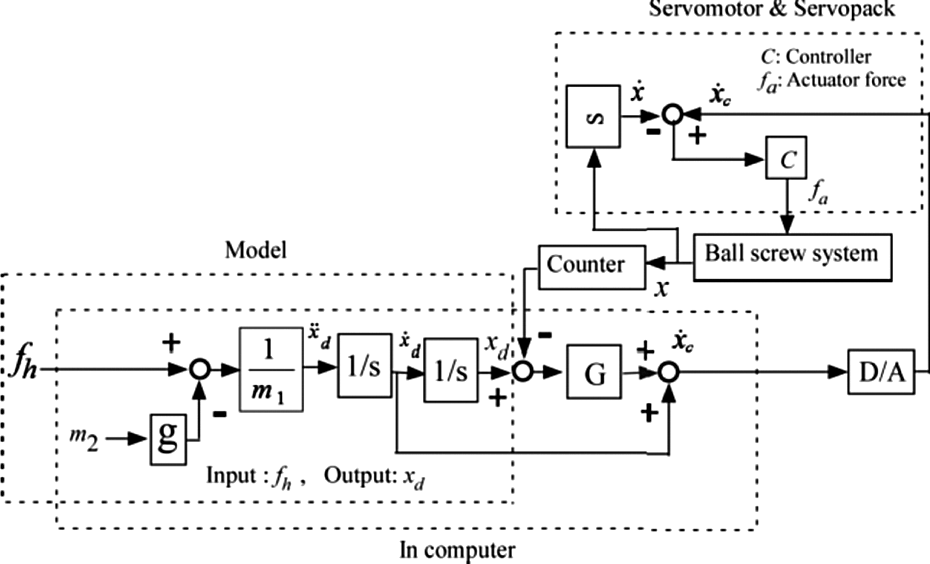
Admittance control algorithm in diagram for the PARS. D/A indicates D/A converter (the servomotor in velocity control mode). PARS: power assist robotic system.
In Figure 2, the control also falls within the FACA because the parameters (m 1, m 2, g, and G) remain fixed.
Design of the test-bed PARS
To evaluate the proposed weight-perception-based FACA, we designed and fabricated a test-bed 1-DoF (vertical up-down motion) PARS using ball screw mechanism actuated by an alternative current servomotor as in Figure 3 (see Table 1 for specifications of the components). As shown in Figure 3(a), the servomotor (with encoder) and the ball screw were coaxially fixed on a metal plate, which was then vertically attached to a wall. The ball screw converted the rotary motion of the servomotor to the linear motion. A force sensor was attached to the ball screw nut through an acrylic resin block. One end of a universal joint was tied to the force sensor and the other end was attached to a wooden block. We built three rectangular objects/boxes (called PAOs) of different sizes by bending aluminum sheets (0.0005 m thick). Top side of each box was covered with a cap made of aluminum sheet (0.0005 m thick).The bottom and back sides were kept open. An object was tied to the force sensor through the wooden block and it could be lifted by a human as shown in Figure 3(b). Dimensions (length × width × height) and self-weights of the boxes are given in Table 2. Figure 4 shows the experimental setup for the PARS.

(a) The main power assist device and (b) the complete device with a medium size object (PAO), where the PAO (aluminum box) is tied to the wooden block at its upper part. The PAO is kept on the foam before it is lifted by a human. The human may grasp the PAO at its center and lift it for the unimanual case. Two handles may be attached to the PAO to lift it bimanually, and two force sensors may be set in the handles for the separate force sensor case. PAO: power-assisted object; PARS: power assist robotic system.
Technical specifications of the servomotor, ball screw, and the force sensor.

Dimensions and self-weights of the PAOs.
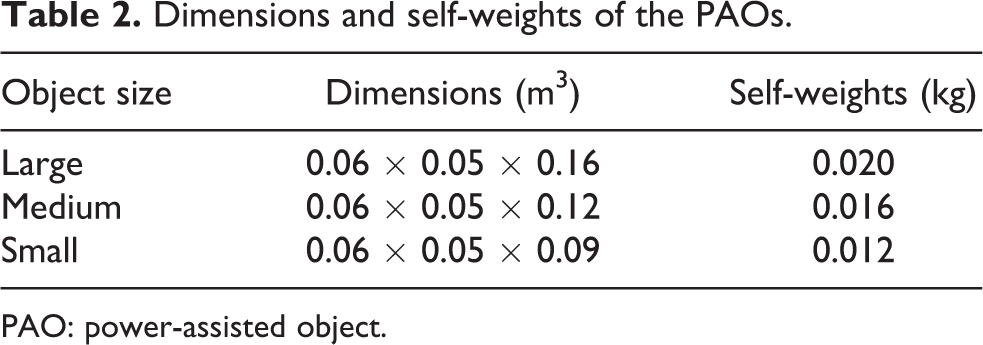
PAO: power-assisted object.
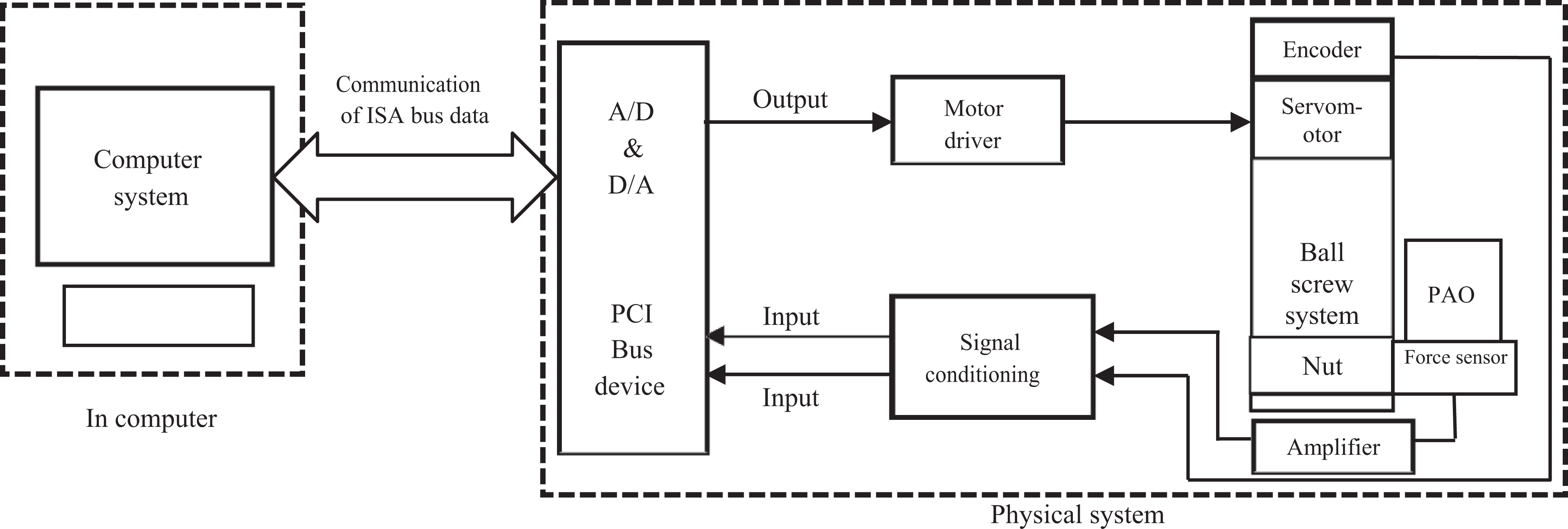
Experimental setup and communication for the PARS for lifting objects. A noise filter (LF-205A) was added to the power supply. PARS: power assist robotic system.
Although the mechanical design of the PARS is simple, we think that it may be sufficient to address our objectives. We aim to compare human features for the proposed control algorithms for object manipulation with the PARS to that for manual manipulation of objects available in psychology literatures to ensure that the results for the algorithms fit with human psychology. However, the psychological experiments usually use lightweight objects. 17,21 –23 Hence, the lightweight objects in our setup may help compare the control evaluation results to that of the psychology experiments on similar basis. Again, when handling heavy loads with power assist in industries, the human should have the same feeling of handling a lightweight object. 3 Using lightweight objects, we want to realize how the proposed control algorithms produce human feelings and HRI for lightweight objects so that similar feelings and HRI can be exploited when the algorithms are used to handle heavy objects. However, modification of the structure of the power assist device should be performed to make it suitable for handling heavy loads (see literatures 6,8,12,24 where similar simple 1-DoF PARSs were used to evaluate the control strategies).
We made three non-power-assisted objects (NPAOs; Figure 5). NPAOs were lifted manually by humans. Shape, dimensions, materials, weights, and appearance of a NPAO of particular size were same as that of the PAO of that particular size. NPAOs were used as reference weights to estimate the haptically perceived weights of the PAOs.

Front views of the large, medium, and small NPAOs (at left) and their backs (at right). Extra mass attached to the back helps change the NPAO weight keeping the front view unchanged. NPAOs: non-power-assisted objects.
Evaluation of the weight-perception-based FACAs
We evaluated the FACAs for unimanual and bimanual schemes using the test-bed PARS through an experiment (experiment 1) as described below.
Experiment design
The independent variables were the lifting schemes (unimanual, bimanual with common and separate force sensors), m 1 and m 2, and object sizes. The dependent variables were the haptically perceived weights (called power-assisted weights (PAWs)), power assistance, load forces, object displacement and acceleration, HRI, and manipulation performance (efficiency and precision).
Subjects
Twenty engineering students (18 males and 2 females) aged between 22 and 30 years (mean (M) = 23.63 years, standard deviation (SD) = 1.26) were selected to participate in the experiment voluntarily. They were believed to be mentally and physically healthy with sound vision, memory, sensory, and cognitive skills and were instructed about the experiment procedures, which were approved by the ethical committee of the university.
Experiment procedures
We nominated 12 m 1 and m 2 pairs of values (see Table 3) based on our experience. The control system of Figure 2 was implemented using MATLAB/Simulink (version R2010b) (solver: ode4, Runge–Kutta; solver type: fixed step; sample time: 0.001 s, and G = −5) for each lifting scheme separately. For unimanual scheme, each subject lifted each size PAO separately for each m 1 and m 2 pair. We selected m 1 and m 2 pair randomly (e.g. m 1 = 1.5, m 2 = 0.5) for the control system and maintained its confidentiality. For each trial, the subject had to lift the PAO, maintain the lift for a few seconds at a targeted height of 0.1 m, 8 and then release the object. The subject then needed to manually lift a NPAO using right hand alone for reference weights. We changed the NPAO weight in a descending order starting from 1.5 kg and ending at 0.1 kg maintaining an equal difference of 0.05 kg, that is, 1.5, 1.45,…,0.15, 0.1 kg. The subject compared the haptically perceived PAO weight to that of the NPAO (reference weights) and estimated the magnitude of the PAW following the “constant stimuli” method of psychophysics. 19 Such estimation was feasible as the human might be able to remember the PAW until its magnitude was estimated through comparison with the reference weights. 25 After each trial, the subject evaluated the HRI in a few terms (see Table 4) following a subjective rating scale (Likert-type scale 26 ) as in Figure 6. We considered the pHRI as it might have direct impact on safety and performance. 27 The experimental procedures are shown in Figure 7(a). In each trial, we recorded the load force, PAW, kinematics data, pHRI score, and the total time of the lift (grasp, lift, and object release) separately.
Values of m 1 and m 2 used in the experiment.

pHRI evaluation criteria.

pHRI: physical human–robot interactions.

pHRI evaluation scale (scores are in parentheses). pHRI: physical human–robot interactions.

(a) In a unimanual trial, a human lifts a PAO (marked as A) and then compares its haptic weight to that of the NPAO (marked as B) and (b) in a bimanual trial (common force sensor case), a human lifts a PAO (marked as A) by gripping two handles with two hands and then compares the haptic weight of the PAO to that of the NPAO (marked as B) (but NPAO was lifted by one hand). The whole PARS except the PAO was covered with a cloth to eliminate visual differences between the NPAO and the PAO, which might eliminate any bias in the psychophysical estimation of the PAW. PAO: power-assisted object; PARS: power assist robotic system; NPAOs: non-power-assisted objects.
Experimental procedures for the bimanual schemes were same as that used for the unimanual scheme except the differences that the subjects grasped the handles of the PAO at the designated places using power grips of both hands (see Figure 1(b) and (c)) and then lifted the PAO. Figure 7(b) shows the experimental procedures for the bimanual lift with a common force sensor case as an example. The force sensor in each case measured the load force only and the moment was not measured. Each subject was instructed to lift the object in such a way that the grip axis was aligned vertically with the center of mass of the object so that any rotational dynamics and torques could be eliminated. Again, for the bimanual lifts, the PAOs were grasped at handles, but the NPAOs (reference weights) were grasped at the centers of their bodies. Hence, differences in grasp configurations between PAO and NPAO might affect the PAW estimation. However, we ignored it as such effects would be minor. 22,28
Evaluation results for the weight-perception-based FACAs
Computation of power assistance
Figure 8 shows linear psychophysical relationships between actual weights and the PAWs for the small size object. The figure shows that m 1 does not affect weight perception in both lifting schemes, and the weight perception is due to the gravitational mass (m 2) only, which justifies our hypothesis that the inertia and the gravity for the PARS have differential effects. Figure 8 also shows that the PAWs for the bimanual lifts are lower than that for the unimanual lifts. The reason may be that weight perception with one hand is based on the integrating effort signals resulting from muscular activity to support the arm and the weight against the gravity. When lifting an object bimanually, the magnitude of the effort signals due to supporting the arms and the weight against the gravity may change in opposite ways: the posture effort signals increase due to the employment of two hands, while the weight effort signals decrease due to sharing the weight between two hands. 18,21 Again, the relationships between the actual weights and the PAWs for two different types of bimanual schemes (common force sensor and separate force sensors) are the same. It indicates that the arrangement of force sensors in the mechanical design did not affect the weight perception for the bimanual lifts.

Psychophysical relationships between actual weights (simulated weights, m 2 values of Table 3) and PAWs (haptic weights) for the small size object for unimanual and bimanual lifts. PAW: power-assisted weight.
We derived computational models to compute the reduction in perceived weight (RPW) and power assistance level (PAL) as given in equations (6) and (7) respectively, where PAW is obtained from Figure 8 for a particular m 2 value for a particular object size. Table 5 shows the RPW and the PAL for all values of m 2 for the small size object for different lifting schemes. The results showed that the RPW and PAL had linear relationships with m 2, the power assistance was higher for the bimanual lifts than that for the unimanual lift, and the force sensors arrangement in the design did not affect the power assistance level. Analyses of variance (ANOVAs; object size, subject) on PAWs for each m 1 and m 2 pair in each scheme separately showed that variations due to object sizes were statistically nonsignificant (p > 0.05 for each m 1 and m 2 pair in each scheme). The reason might be that the subjects estimated the PAWs using haptic senses where the visual cues had no effects. 17,22 Variations among subjects were also statistically nonsignificant (p > 0.05 for each m 1 and m 2 pair in each scheme), which indicates the generality of the results


Mean (n = 20) PAW and RPW with variances (in parentheses) and PAL for the small size PAO for unimanual and bimanual lifts.

PAW: power-assisted weight; RPW: reduction in perceived weight; PAL: power assistance level; PAO: power-assisted object.
Analysis of pHRI
We determined the mean pHRI scores for three sizes of objects for unimanual and bimanual schemes separately for each of the 12 m
1 and m
2 pairs. Summary of the pHRI evaluation is as the following:
when m
1 < m
2: for m
1 = 0.5 and m
2 = 1.0; m
1 = 0.5 and m
2 = 1.5; and m
1 = 1.0 and m
2 = 1.5, the pHRI scores were greater than −3 but less than −2, that is, −2 > score > −3 for all sizes of objects and for both lifting schemes. This score range may be considered as “worse” according to the rating scale (Figure 6). Hence, pHRI were worse when m
1 < m
2.
when m
1 = m
2: for m
1 = 0.5 and m
2 = 0.5; m
1 = 1.0 and m
2 = 1.0; and m
1 = 1.5 and m
2 = 1.5, the pHRI scores were greater than −2 but less than −1, that is, −1 > score > −2 for all sizes of objects and for both lifting schemes. This score range may be considered as “bad” according to the rating scale (Figure 6). The results showed that the pHRI were bad when the inertial and the gravitational mass were equal, which also justifies our hypothesis.
when m
1 > m
2: for m
1 = 2.0 and m
2 = 1.0; m
1 = 1.0 and m
2 = 0.5; m
1 = 2.0 and m
2 = 1.5; m
1 = 1.5 and m
2 = 0.5; m
1 = 1.5 and m
2 = 1.0; and m
1 = 2.0 and m
2 = 0.5, the pHRI scores were greater than 1 but less than 2, that is, 2 > score > 1 for all sizes of objects and for both lifting schemes. This score range corresponds to “good” according to the rating scale (Figure 6). Out of the six m
1 and m
2 pairs that produced good pHRI, m
1 = 1.0 and m
2 = 0.5 pair produced the best pHRI (highest magnitudes of scores) for each size object for each lifting scheme. Hence, m
1 = 1.0 kg, m
2 = 0.5 kg pair was recognized as the appropriate admittance control parameters, and thus the forthcoming analyses are confined to m
1 = 1.0 kg, m
2 = 0.5 pair only. Table 6 shows detailed pHRI evaluation results for the small size object for m
1 = 1.0 kg, m
2 = 0.5 kg.
Mean (n = 20) pHRI evaluation scores for the small size object for unimanual and bimanual schemes for m 1 = 1.0 kg, m 2 = 0.5 kg.

pHRI: physical human–robot interactions.
We believe that the satisfactory (good) pHRI was the consequence of the inclusion of weight perception in the FACA. The results prove that m 1 < m 2 or m 1 = m 2 is unacceptable, instead m 1 > m 2 should be maintained. Table 6 shows that the pHRI for the bimanual schemes were better than that for the unimanual scheme. We assume that the lower perceived heaviness (Figure 8) and the higher PAL (Table 5) for the bimanual schemes helped produce better pHRI over the unimanual scheme. Again, for the bimanual schemes, the human gripped the object more comfortably at the handles, bilateral haptic communications and information sharing between the handles and the human hands as well as the control over the gripped handles were very strong, which might produce the better pHRI. 3,4,18,21 Again, between the two bimanual schemes, the bimanual scheme with separate force sensors produced slightly better pHRI than that produced by the bimanual scheme with a common force sensor. ANOVAs showed that the variations due to object sizes were statistically nonsignificant (p > 0.05 for each m 1 and m 2 pair in each scheme). The reason might be that the subjects evaluated the pHRI based on haptic senses where visual cues had no influences. 17,22
We see that the PAL and the pHRI were different for the unimanual and the bimanual lifts. The PAL might also affect the pHRI. As of equation (7), PAL is a function of admittance parameter, m 2. Hence, PAL and pHRI may be adjusted for the unimanual and the bimanual lifts through adjusting the value of m 2 though a user-accepted trade-off between the PAL and the pHRI is necessary.
Analysis of kinematics
Figure 9 shows the time trajectories of the object’s displacement and acceleration for a typical trial for the small size object for the bimanual scheme. The figure shows displacement overshoot (>0.1 m) and multi-peaked displacement trajectory (the human took the object slightly up, then took down and again took up). The multi-peak displacement might reduce the object velocity, which might be the human’s strategy to adjust with high acceleration. The figure shows that the peak acceleration (at 12 s) occurred during the initial phase of the lift.

Typical time trajectory of (a) displacement and (b) acceleration for a trial in the bimanual scheme (common force sensor case) when a subject lifted the small size PAO with the system at m 1 = 1.0 kg and m 2 = 0.5 kg. The circled portions indicate the initial phases of the lift. PAO: power-assisted object.
Table 7 shows the mean peak acceleration for different sizes of objects for m 1 = 1.0 kg, m 2 = 0.5 kg. The results show that the mean peak accelerations for the bimanual scheme were smaller than that for the unimanual scheme. 18,21 We believe that the lower perceived weights for the bimanual scheme (Figure 8) might contribute to the smaller peak accelerations, 17 which might produce better pHRI for the bimanual schemes (Table 6). Again, for the bimanual scheme, mean peak accelerations for the two separate force sensors case were smaller than that for the common force sensor case though the perceived weights for the two cases were the same (Figure 8). We assume that the lower accelerations might be responsible for the better pHRI for the separate force sensors case (Table 6). The accelerations were proportional to object sizes. 17
Mean (n =20) peak accelerations (m/s2) with standard deviations (in parentheses) for the unimanual and the bimanual lifting schemes for m 1 = 1.0 kg and m 2 = 0.5 kg condition.

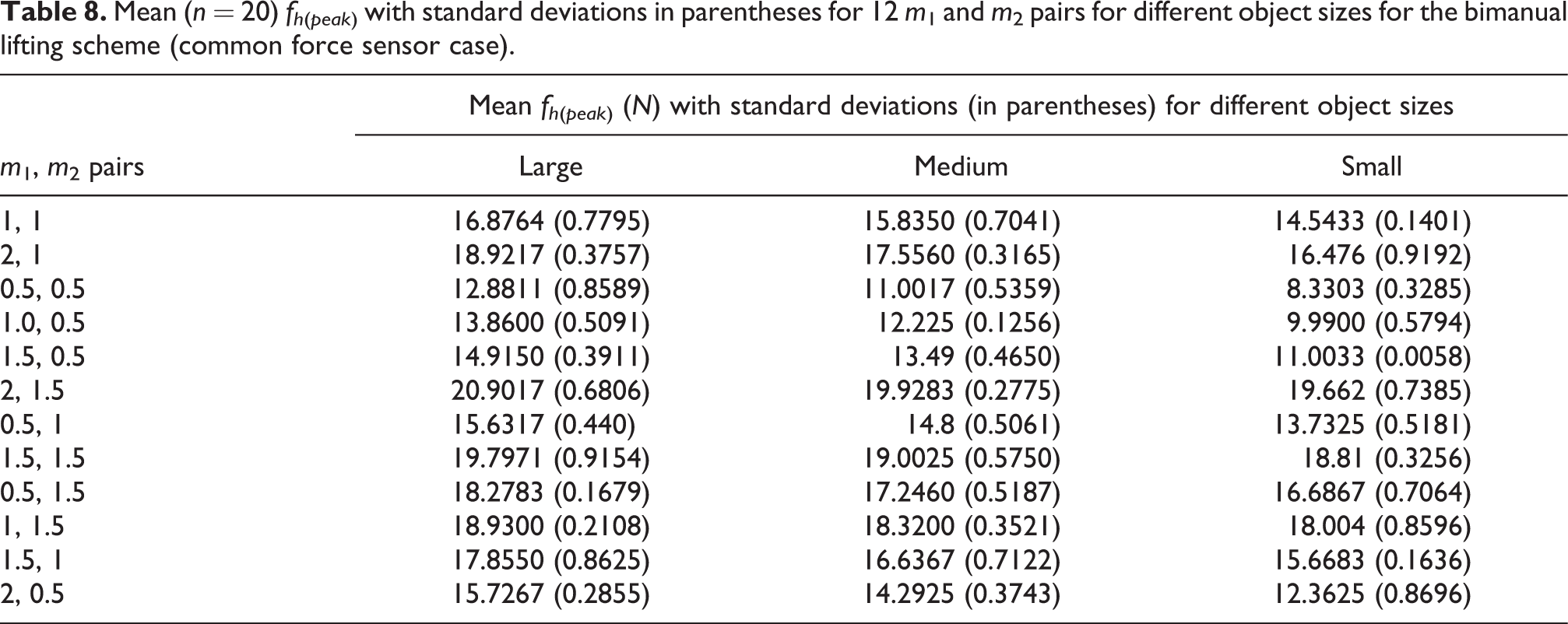
Analysis of kinetics and computation of excess in load forces
Figure 10 shows the typical time trajectory of load force (fh ) for a trial in the bimanual scheme (common force sensor case). In the figure, the peak load force (PLF) is the peak of fh , which is abbreviated as fh (peak) and the static force is the actual (simulated) weight (m 2 g). We see that the trajectory of load force (Figure 10) and that of acceleration (Figure 9) are synchronized. We derived the magnitude of fh (peak) for each trial (for each of 12 m 1 and m2 pairs) for each object size in each lifting scheme and determined the mean fh (peak). The mean fh (peak) for different m 1 and m 2 pairs for different sizes of objects for the bimanual scheme (common force sensor case) is shown in Table 8. The table shows that, out of the six pairs of m 1 and m 2 (where m 1 > m 2) that produced good pHRI (see section “Analysis of pHRI”), fh (peak) is the lowest at m 1 = 1.0 kg and m 2 = 0.5 kg for each object size. We believe that the lowest fh (peak) at m 1 = 1.0 kg and m 2 = 0.5 kg contributed to the best pHRI (Table 6).

Time trajectory of load force for a trial in the bimanual scheme (common force sensor case) when a subject lifted the small size PAO with the PARS at m 1 = 1.0 kg and m 2 = 0.5 kg. The circled portion indicates the initial phase of the lift. PAO: power-assisted object; PARS: power assist robotic system.
Mean (n = 20) fh (peak) with standard deviations in parentheses for 12 m 1 and m 2 pairs for different object sizes for the bimanual lifting scheme (common force sensor case).
On the other hand, the actually required fh
(peak) to lift a PAO with the PARS by a human is slightly larger than the PAW at each m
1 and m
2 pair.
17
For example, for m
1 = 1.0 kg and m
2=0.5 kg, the PAW is 0.15 kg or 1.4715 N for the bimanual scheme (Figure 8). Hence, fh
(required) (the actually required fh
) can be calculated by equation (8), where Δ is a small increment of PAW. We then derived a computational model of fh
(excess) (the excess in the fh
) as in equation (9). Table 9 shows the computed fh
(excess) for the bimanual lift. Similarly, we determined the fh
(peak) for each pair of m
1 and m
2 for each size object for the unimanual and the bimanual schemes (separate force sensors case) and computed fh
(excess) for each size object for m
1 = 1.0 kg and m
2 = 0.5 kg. We assume that the excessive load forces for the power-assisted lifts might be the reason of the excessive accelerations as in Table 7


Determination of fh (excess) for different sizes of objects for bimanual lifting (common force sensor case) for m 1 = 1.0 kg and m 2 = 0.5 kg.

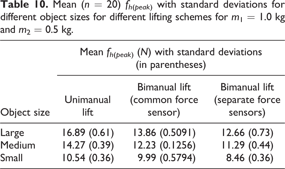
The mean fh (peak) for different object sizes for different lifting schemes for m 1 = 1.0 kg and m 2 = 0.5 kg are compared in Table 10. The results show that the mean fh (peak) (and fh (excess)) for the bimanual cases were smaller than that for the unimanual case. 18,21 We believe that the lower perceived weights for the bimanual scheme (Figure 8) might be responsible for the lower fh (peak) and fh (excess). 17 Again, between the two bimanual schemes, the mean fh (peak) and fh (excess) for the separate force sensors case were slightly lower than that for the common force sensor case. It might happen due to the reason that the human might be psychologically motivated to apply less load force when the human could realize the presence of force measurement devices at the grasping points. The ergonomic reasons might be that intuitiveness, reflection of user’s intention through input forces, haptic engagement, interactivity, information sharing, guidance to motion through sensing, and naturalness might increase when closeness between human hands and force sensors increased for the separate force sensors case. 3,4,10 We believe that lower load forces produce lower accelerations (Table 7) and better pHRI (Table 6) for the separate force sensors case over the common force sensor case. The fh (peak) and fh (excess) were proportional to object sizes. 17
Mean (n = 20) fh (peak) with standard deviations for different object sizes for different lifting schemes for m 1 = 1.0 kg and m 2 = 0.5 kg.
Variable admittance control
Variable admittance control algorithm
We see that, for m 1 = 1.0 kg and m 2 = 0.5 kg, the pHRI were good (Table 6), but there are still problems that the peak accelerations are large (Table 7), fh (peak) are excessive (Table 9), and there is overshoot in displacement (Figure 9). We argue that the good pHRI was achieved due to the consideration of weight perception in the controls. However, we believe that there is still scope to enhance the pHRI to the “better” or to the “best” level, which may be achieved if we can reduce the peak accelerations through reducing fh (peak) . One strategy of reducing fh (peak) is to send a reduced portion of fh to the control system in Figure 2. In this case, the reduced fh may reduce the acceleration, but it may also affect the system characteristics and human’s haptic perceptions adversely (e.g. it may change the perceived weight as fh is related to m 2 g in equation (4)). Alternatively, we see in Figure 8 that m 1 has no effect on haptically perceived weights, but m 1 is directly related to fh as in equation (4), given that m 2 g is fixed. Hence, an exponential decay in m 1 when the human lifts the object with the PARS may reduce fh (peak without altering the human’s haptic feelings, which may also reduce the acceleration. The exponential decay in m 1 may be expressed in general as equation (10), where k is the initial time, m 0 is the initial value of m 1(at k), t is the time when the exponential decay ends, T is the duration of the exponential decay and α is the decay constant. Here, T = t − k, and T = t if k = 0. The VACA is constituted by equation (10) where the admittance parameter (m 1) varies at specified times. The novelty is that only the inertia mass (m 1) varies instead of the gravity mass (m 2), 10 which can modulate the acceleration separately through reducing fh without altering haptic perceptions. The VACA is also a method of active compliance to improve the pHRI and the manipulation performance

To adjust with specific requirements or to address situations on dynamic contexts, robustness of the VACA may be increased in several ways: (i) exponential decay may be arranged consecutively for n times (where n is any positive real number) during a single lifting trial and (ii) the values of α, m 0, k, t, and T may be modulated.
Formulating variable admittance control strategy
The general VACA in equation (10) may be customized to solve the particular problems of the PARS. The customized VACA for the PARS based on equation (10) is shown in Figure 11 as a flowchart and is explained below. Here, we used n = 2. We see in Figure 9 that the peak acceleration occurs during the initial phase of lifting (circled portion). More specifically, the acceleration starts to rise at about 11.7 s when the object is just started to be lifted (the object is at 0.005 m height) and the acceleration reaches the peak at about 12 s (when the object is at about 0.06 m height). Then, the acceleration drops to about zero (0) at about 12.3 s. The fh (Figure 10) is synchronized with the acceleration trajectory. Hence, the control strategy first arranges an exponential decay of m 1 at the beginning of the lift (when the object is at 0.005 m height at around 11.7 s, i.e. k 1 = 11.7 s, and the decay ends at about 11.9 s, i.e. t 1 = 11.9 s and T 1 = (11.9−11.7) s = 0.2 s) and then arranges another exponential decay of m 1 before the acceleration reaches the peak (when the object is at 0.055 m height at around 11.93 s, i.e. k 2 = 11.93 s, and the decay ends at about 12.13 s, i.e. t 2 = 12.13 s and T 2 = (12.13−11.93) s = 0.2 s).
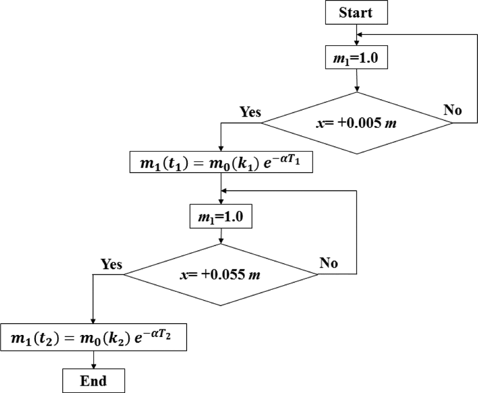
Novel variable admittance control strategy.
The heights 0.005 and 0.055 m, the timings 11.7 and 11.93 s, and n are decided empirically. We believe that two consecutive decays in m 1 during the lift of the object may significantly reduce the fh (peak) (and acceleration), which may significantly improve the pHRI and the manipulation performance. For each of the two separate exponential decays of m 1, we assumed m 0 = 6.0 kg (a large initial value of m 1 at 11.7 s and 11.93 s), it then reduced to m 1 = 1.0 kg within 2 s. We calculated α following equation (10), which was 18.961 s−1.
We see in Figure 11 that t, k, and T were customized to fit with the specific requirements. Instead, the triggering of the exponential decay may be decided based on the specified displacement/height of the object, and the corresponding values of t, k, and T may be used in equation (10), which may enhance the robustness of the algorithm.
Evaluation of the VACA
Procedures of the experiment
We, for this experiment (experiment 2), implemented the control system of Figure 2 again for all three sizes of objects and for both unimanual and bimanual schemes following the same procedures as used for experiment 1. However, we used m 1 = 1.0 kg and m 2 = 0.5 kg only as the admittance control parameters, and the admittance was varied following Figure 11 for each trial of lifting.
Results of experiment 2
We determined the mean fh (peak), peak acceleration, and pHRI evaluation scores for each size object for each lifting scheme for the VACA as shown in Tables 11 to 13.
Mean (n = 20) f h(peak) for different object sizes for different lifting schemes for the VACA.

VACA: variable admittance control algorithm.
Mean (n = 20) peak accelerations (m/s2) for different object sizes for unimanual and bimanual lifting schemes for the VACA.

VACA: variable admittance control algorithm.
Mean (n = 20) pHRI evaluation scores for the small size object for unimanual and bimanual lifting schemes for the VACA.

pHRI: physical human–robot interactions; VACA: variable admittance control algorithm.
Reduction in peak load forces and peak accelerations
If we compare the mean fh (peak) and peak accelerations for the VACA (experiment 2) to that for the FACA (experiment 1 conducted at m 1 = 1.0, m 2 = 0.5 only) for both unimanual and bimanual schemes, we observe that the PLFs and peak accelerations reduced significantly in both schemes for the VACA. We argue that reduction in PLFs reduced the peak accelerations consequently. We also observe that the mean PLFs and peak accelerations for the bimanual schemes are lower than that for the unimanual scheme. Again, between the two cases of the bimanual schemes, the mean PLFs and peak accelerations for the separate force sensors case are lower than that for the common force sensor case.
Improvement in pHRI
We compare the results of Table 13 to that of Table 6 and observe that the pHRI significantly improved for both lifting schemes due to the application of VACA. We believe that the reduction in PLFs (Table 11) caused the reduction in the peak accelerations (Table 12), which consequently improved the pHRI. We also observe that improvements in the pHRI for the bimanual schemes were higher than that for the unimanual scheme. We believe that the lower PLFs and peak accelerations for the bimanual schemes were responsible for the higher pHRI. Again, between the two cases of the bimanual schemes, the pHRIs for the separate force sensors case were better than that for the common force sensor case. Lower PLFs and peak accelerations for the separate force sensors case might be responsible for the higher pHRI over the common force sensor case.
Improvement in manipulation performance
We expressed the co-manipulation performance in terms of precision and efficiency. Deviation from target position (e.g. displacement overshoot) is used as a criterion to measure the precision objectively as in equation (11), where Pt is the target position and Pm is the measured position. Manipulation efficiency is the ratio between the targeted manipulation time (Tt ) and the measured manipulation time (Tm ) as in equation (12). Table 14 compares the precision and efficiency between the FACA and the VACA. Results show that precision and efficiency significantly improved due to the VACA. We believe that the active compliance by the VACA improved the precision through reducing the PLFs and accelerations. The improved efficiency might be the effect of the improved compliance and pHRI
Comparison of performance between FACA and VACA (values inside parentheses indicate standard deviations).

VACA: variable admittance control algorithm; FACA: fixed admittance control algorithm.


Discussion
The presented results seem to be effective for real applications of manipulating heavy objects in industries. However, the effectiveness of the proposed control algorithms may be enhanced and the algorithms may perform better if the following conditions are addressed properly: Force/torque sensor and position sensor used for the system are properly calibrated and arranged as the results show that force sensor arrangement has impact on system characteristics, human–robot interaction and manipulation performance.
29,30
Accuracy, precision, resolution, and sensitivity of the sensors should be appropriate. The system response should be made faster. A direct drive motor, a fast processor, and fast communication protocols may be considered.
31,32
Attachment between the object and the force sensor is very critical. In real applications, it is better to have direct contact between object and force sensor. For multi-DoF manipulation, the force/torque sensor should sense force/torque along each manipulation axis properly.
33
Human’s gripping style (e.g. power grip and precision grip) and gripping location and arrangement (e.g. gripping at the center of the object and gripping at the handles) should be appropriate for the targeted manipulation.
34
m1
, m
2, and G values should be estimated properly. A range of values for each of these parameters should be determined. The algorithms work better if these parameter values remain within the specified ranges. These values should be general, but it is better to customize properly for each particular type of application (e.g. each object/subject group and unimanual/bimanual manipulation). For multi-DoF manipulation, m1
, m
2, and G may be customized for each axis of manipulation.
35
The parameters of the VACA in equation (10) and in Figure 11 should be estimated properly and be as much general as possible, but it is better to customize them properly for each particular application (e.g. each object group, subject group, and unimanual/bimanual manipulation).
36
These parameters are estimated empirically. It should be emphasized that the empirical estimation matches the requirements of each particular application. It is the load force (fh
) that will give motion to the system through the control application. If fh
is ignored (say, fh = 0), it may happen that fa
≠ 0, and the PARS may move the object upward as fa
≠0, but the system is no longer a human–robot system. Instead, it may be a pure automatic system, which is not flexible as we mentioned in section “Introduction.” Hence, fh
≠ 0 should be maintained during real applications so that the algorithms can provide expected flexibility in operations.
37
For bimanual separate force sensors case, fhl
≈ fhr
should be tried to be maintained. An external noise filter added to the power supply may help the algorithms work accurately. Selection of the noise filter will depend on the noises likely to be present in the environment where the system will be operated.
38
Although the human features for lightweight objects should be useful for all cases including heavy object manipulation, the human features may be further investigated for manipulating heavy objects to estimate control parameters, and robot configuration and structure should be designed appropriately for the targeted heavy object manipulation in real applications.
39
Appropriate trainings and instructions to the operators may help the algorithms contribute better and adjust with different situations.
The algorithms may likely fail or the effectiveness of the algorithms may reduce if above conditions are not satisfied fully.
Conclusions and future works
We presented weight-perception-based FACA and VACA for a PARS for lifting objects under unimanual and bimanual schemes. We derived computational models for power assistance, excess in load forces, and manipulation performance and developed an evaluation scheme for pHRI. The novelties were that the controls included weight perception and the admittance was varied to modulate the kinetics and kinematics without altering the haptic perceptions. The results showed that inclusion of weight perception in the FACA produced good HRI and performance that were further improved by the VACA. The bimanual scheme produced less PLF, acceleration, and perceived heaviness and higher power assistance, HRI, and performance than those produced by the unimanual scheme. The bimanual scheme with separate force sensors produced better kinematics, kinetics, HRI and performance over the bimanual scheme with a common force sensor. The VACA parameters can be adjusted to adjust the PAL, HRI, and performance discriminating unimanual and bimanual manipulation. The results reveal novel ideas and approaches regarding human-centric active compliance controls that may help design controls for power-assisted manipulation of heavy objects in industries, which may provide satisfactory HRI and performance.
In future, we will use the results to develop the controls of a multi-DoF PARS for manipulating heavy objects. We believe that the evaluation results for the controls with lightweight objects will be scalable to heavy weights as the heavy loads will be borne by the robot structure, the control algorithms will enable the human to feel as if he/she handles a lightweight object, and the load force will provide only motion to the system, which will be regulated by the VACA. We will also evaluate cognitive HRI (workload, situational awareness, and trust) for the system.
Footnotes
Declaration of conflicting interests
The author(s) declared no potential conflicts of interest with respect to the research, authorship, and/or publication of this article.
Funding
The author(s) received no financial support for the research, authorship, and/or publication of this article.