
Abstract
This paper describes the design and the control architecture of an unsupervised robot developed for grit blasting ship hulls in shipyards. Grit blasting is a very common and environmentally unfriendly operation, required for preparing metallic surfaces for painting operations. It also implies very unhealthy and hazardous working conditions for the operators that must carry it out. The robot presented here has been designed to reduce the environmental impact of these operations and completely eliminate the health associated risks for the operators. It is based on a double frame main body with magnetic legs that are able to avoid the accumulation of ferromagnetic dust during its operation. The control system presents a layered structure with four layers that are physically distributed into two separate components in order to facilitate different operational modes as well as to increase the safety requirements of the system. A low-level control component has been implemented on the robotic unit itself, and a mission planning and control component has been developed on a base station that is also used for interaction with the operator, when the monitoring of the robot's operation is required. This base station component contains three layers of the control system that permit the manual, semiautonomous and autonomous operation of the whole system. A prototype of the robot has been implemented and tested in realistic environments, ascertaining that the design and the control system are perfectly suited to the functions which the robot must carry out.
1. Introduction
Shipyards are a paradigmatic example of a dynamic and unstructured environment where the real application of robots presents a very significant challenge. These types of environments are very extensive, requiring moving robotic platforms, and in constant change, making them very difficult for traditional robotic approaches. The different operators and tools that are required are usually carried to the product itself (ship or marine structure) and move over it, as opposed to the way things are done in more traditional assembly lines. Thus, any robot that has to work in these settings will be faced with a constantly changing product that grows as construction proceeds. At the same time, the robot needs to move and operate in an environment that is filled with all kinds of changing obstacles: other moving robots or humans, scaffolding, machinery, etc. As a consequence, shipyards are among those industries with a low degree of robot penetration.
Notwithstanding the previous comments, some groups and companies have addressed the introduction of robots in these environments since the end of the Eighties [1]. However, these systems have not really been adopted by the industry until much more recently, and only for specific and very controlled and simplified operations, such as inspection [2], welding [3, 4], and hull cleaning [5]. The aspect which the authors of the different proposals pay the most attention to is how the robots move over the areas they are supposed to work in. In this line, different approximations are possible, going from wheeled robots to different types of walking machines. General introductory reviews of climbing and walking robots in the marine industry, as well as of cooperative robots, may be found in [6, 7] and [8]. Just to cite some of the most recent applications in this line, we should mention those of Fei, Zhao and Wan [9] who developed a climbing inspection robot with four magnetic wheels, and Lee et al. [10] whose proposal is very specialized for a certain type of environment, namely that of double hulls. They have designed a rail runner mechanism that carries a robotized arm for welding in double hull structures.
Surface preparation is a very important operation in shipyards. It involves removing any surface coating (paint or oxides) as well as providing a surface with a given texture that is adequate for the subsequent painting operations [11]. This is a process that is carried out just before painting in order to prepare the metal surfaces. When this operation is performed during the construction of the ship, the objective is for the surfaces to conform to a given texture standard before applying the paint coatings in order to improve durability and coverture. On the other hand, when this operation is carried out during ship maintenance, the objective is usually to first remove the old paint coats and prepare the surfaces for new ones when it is repainted. In both cases, it is an environmentally problematic process, with all kinds of health-related risks, which is usually carried out by human operators.
Different technologies exist for cleaning and stripping metal surfaces, the two most relevant being abrasive blasting and ultrahigh pressure water-jetting [2]. Abrasive blasting is a traditional technique and has been around for more than a century. It consists in blasting the hull with small particles of sand (sand blasting) or metals (grit blasting) using a high pressure jet of fluid, generally air or water, to project these particles onto the surface at very high speeds. It is a very effective technique in terms of the final surface results as, in addition to removing whatever coating is present, it is able to provide a given texture level for the surface. However, it presents many drawbacks when considering the environmental implications of the process and the hazards for the human operators performing the task. It obviously generates a lot of toxic waste, which includes the particles themselves as well as any of the materials that have been stripped off the surface (paint, metal, oxides, etc.). It also involves very unhealthy working conditions for the operators carrying it out, as they have to work in an environment full of small metal or sand particles that bounce off the surface at very high speeds, paint and other toxic particles that are stripped off the surface, as well as being exposed to very high acoustic levels [12, 13] and [14]. As a consequence, over the last few years new environmental regulations have led to an increasing use of ultra-high pressure water jetting as an alternative to abrasive blasting in certain operations. In this case, no particles are used - it is just the water itself, projected at extremely high pressures, which performs the stripping of the surface. Unfortunately, these techniques, although much more environmentally friendly, are generally slower and more costly than abrasive blasting and, more importantly, cannot really prepare steel surfaces for optimal paint adherence, like in the case of sand or grit blasting. They basically remove only the coating that is present. It is for this reason that the most commonly used systems in shipyards are still based on manually operated hoses that project grit at high speeds by injecting pressurized air at a pressure of around 8 kg/cm2.
With the aim of reducing the environmental and health impact of these operations, over the last decade some inroads have been made in their automation [2] and in the development of robots for hull stripping and surface preparation. Most of the work carried out in this line, however, has considered water jetting to be the main stripping technique [15, 16] and [17]. A clear example of this is the Ultrastrip series of Robots developed at the Carnegie Mellon University Robotics Institute [15] and later commercialized by Ultrastrip Systems. These 200+ kg remote controlled robots are based on air gap magnets for fixation and wheels for motion, and they carry around a water jet head within an enclosure for vacuuming the residue in order to reduce the environmental impact of the system. The results obtained by this system were quite successful but, as indicated above, water jetting does not achieve the same level or steel surface preparation as grit blasting systems and, thus, is not appropriate for all cases. It is for this reason that some groups have devoted great efforts to the development of robotic systems capable of safely performing grit blasting operations on ship hulls. One of the main problems here lies in the adherence of the robots to the metallic surfaces, as blasting produces ferromagnetic particles or dust that tends to collect on the fixation magnets, rendering them useless. The authors of [18] tried to solve this problem by using vacuum-based adhesion and moving the robot using four wheels. Others, like Ortiz and his collaborators [19], have addressed the problem through a remote controlled robot arm with a blasting head positioned on an elevation platform that moved over the ground alongside the ship. The externally controlled platform is displaced along the length of the ship and raises the arm to the operational positions. Very high-levels of surface quality can be achieved using this approach. In fact, the quality levels meet the most stringent requirements in the sector. However, on the down side, this system is very cumbersome and costly to run, and its operation, like in the case of Ultrastrip, requires human operators to remotely control the system. This same group proposed another robot [20] based on magnetic treads. Recently, [21] have developed a robot for grit blasting the inside of double hulls. The robot moves by supporting itself on the inside beams of the hull and controls the blasting head through a seven axis manipulator.
Thus, it is clear that there is a need for compact and easy to handle robotic systems that can carry out sand or grit blasting tasks in an autonomous or semiautonomous mode while preserving the environmentally and operator friendly character required for their use in modern shipyards. In other words, a grit blasting system is needed that can compete in terms of environmental friendliness with current water blasting systems and which is not hazardous for human operators. At the same time, this system should be able to attach itself and move securely over the surface as well as receive protection from the effects of the grit and particles generated during the blasting operation.
To fulfil these requirements, which have not been covered by any system yet, in this work we present a novel small, light and autonomous robotic grit blasting system that can achieve the same or even better surface quality results than those provided by a human operator while minimizing the amount of waste the environment has to support. Two main blocks make up the grit blasting system: a closed circuit grit blasting head that recovers the grit and the stripping residues through a vacuum system - which is being developed jointly with the research department of the Navantia Shipyards in Spain - and a semi-autonomous climbing robotic system which is able to perform the whole surface preparation operation with very little human assistance.
The objective of this paper is to present a semi-autonomous climbing robotic system that carries the blasting head as well as the elements that participate in its control. It is based on an 80 kg sliding type pneumatically actuated structure similar to [22] that can walk on the hull carrying the blasting head while cleaning an 80 cm wide path as it moves. It is attached to the surface of the hull by means of a NdFeB permanent magnet-based fixation system whose individual elements can be demagnetized, as needed by means of internal demagnetizing coils. A double sliding structure provides enough degrees of freedom for the system to turn as desired, avoiding obstacles and comply with the curved shape of the hull. The robot is quite modular and can accommodate an image-based quality verification subsystem that modulates its operation in order to provide a homogeneous quality level throughout the surface.
The paper is organized as follows: Section 2 is devoted to the description of the architecture and the kinematics of the robot. A description of the control system is provided in section 3. In section 4 we present some examples of the real operation of the robot and, finally, section 5 provides some conclusions of this work.
2. Robot architecture
The design of the robot architecture has been carried out taking into account that its primary mission is grit blasting. As a consequence, it should be able to navigate on the hull surface, transporting the blasting head and moving it according to certain rules while fulfilling a series of actuation and safety requirements. One of these requirements imposes that, in the case of a total loss of the power supplied to the robot, it should remain stationary in its current location and entirely attached to the hull. For this reason, we have resorted to the use of permanent magnets as a means of attachment. However, since some of the blasting materials are ferromagnetic, the magnets need to be placed away from the blasting head and demagnetized at some points during the robot's operation in order to avoid the attachment of large amounts of grit. Thus, we have opted for a legged robot with magnets - which are demagnetized when moving away from the hull surface - as its feet. Starting from this proposition and taking into account the robot's primary purpose, its architecture has been finally based on a double frame main body. We found that this design facilitates the sideways oscillating motion of the blasting head while the robot is advancing in a straight or mildly curved path, which are the basic actuations needed for the robot to be able to accomplish its task. The robot architecture and different aspects of its design and motion are described in the following subsections.
2.1. Mechanical Design
The robot architecture (Fig. 1) is based on two four-legged frames or modules linked through two complex joints allowing them to move relative to each other while allowing the whole robot to walk. Some details of the robot kinematics are shown in Fig. 2. We have resorted to pneumatic actuators for all of the moving parts. The main reason for this choice is that they are light and that - due to the compressibility of air - movement driven by pneumatic actuators is passively compliant, facilitating the absorption of vibrations or small irregularities and thus leading to safer operation
The first complex joint is made up of the S1 and S3 slides and the passive R1 joint, which is just a bearing. The second one is made up of the S2 and S4 slides and the passive R2 joint, which is similar to R1. All four slides, except for S4, are driven by pneumatic linear actuators, being S4 passive. The lower module has four legs that are driven by linear actuators (T5-T8) and which are coupled to magnets at their feet through ball and socket joints (BS5-BS8). This way of coupling allows the magnets to adapt to small angle deviations of the hull surface, increasing their grip. This module has a double action linear actuator that drives slide S3, which is mounted aligned with respect to S4. It is on these two elements (S3 and S4) where the two bearings (R1 and R2) are mounted. These R1 and R2 joints are linked through their top ends to the S1 and S2 slides mounted on the upper frame, thus linking the two modules together. This way of coupling both modules permits relative linear displacements between them along two axes, as well as the rotation of the modules relative to each other. Therefore, this arrangement of the modules allows the robot to advance, to change its direction, and to move horizontally.
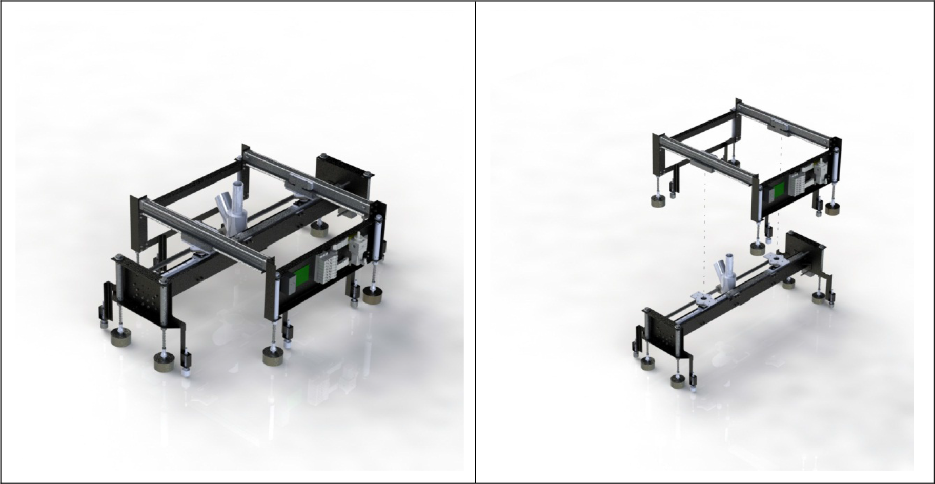
The complete robot (left) and the lower and top modules (right)
The grit blasting head and a vision and quality control subsystem are mounted on the lower module. The quality control subsystem consists of two intelligent cameras provided with illumination elements. One is placed before and the other behind the blasting head, allowing vision-related alignment and blast strip length control tasks. In fact, one of the cameras sees the surface just before being blasted and the other just after blasting. The former is located before the advancing blasting head and discriminates between the blasted and non-blasted regions, allowing the correcting of the robot trajectory. The latter is located behind the head and allows the performance of surface quality verification. Obviously, the cameras switch their functions depending on the direction of the motion of the head. Both the cameras and the blasting head are moved together by means of a linear actuator (S5).

Robot kinematics diagram
The top module is a frame formed by a rigid rectangular structure that has four actuated legs located at the vertices of the rectangle. These are identical to the legs of the lower module. It also presents two parallel linear actuators driving the S1 and S2 slides that move along two parallel sides of the rectangular frame. These actuators are in charge of the vertical motion of the robot on the hull when actuated together and in charge of the performance of relative rotations between the modules when actuated independently. In these actuators, a pneumatic breaking system in the slider prevents the vertical displacement of one module with respect to the other.
When one module moves, the other remains attached to the hull by its four legs. In case of power failure, the air in the leg actuators is purged and all eight feet are placed on the surface. This attaches the robot to the hull. Before moving, each module demagnetizes its magnets and retracts its legs. In order to prevent uncontrolled moments from appearing at the couplings of the modules, there is a mechanical support element beside each magnet consisting of a leg with a spherical wheel.
2.2. Motion of the Robot
The operation of grit blasting the hull is carried out as follows. The robot is placed on the hull. The blasting compressor is turned on and the head starts blasting away. The compressor is not turned off until the end of the operation. The robot starts by moving both the top module and the blasting head horizontally, allowing blasting a strip of around 80 cm, until the head reaches the end of the working area. The bottom module slides up appropriately and the blasting head and the top module begin to move horizontally in the opposite direction, until they reach the end of the working area on the other side. During this sequence, the magnets and the actuators in the legs of the modules must be activated appropriately so as to attach or move the module at the corresponding instant of time.
Consequently, the head will blast horizontal strips stacked on top of each other until the bottom module reaches the upper end of the top module. At this point, the bottom module is fixed to the hull surface and the top module is displaced up until the bottom module is located at its bottom, whereupon the operation resumes as before. When the top of the area which must be grit blasted on the ship hull is reached, the bottom module is moved completely to one side of the top module; it is then fixed to the hull and the top module is displaced over it until it reaches a position where a new vertical strip can be blasted. Then, the blasting operation starts again, this time descending down the hull. The sequence of motions performed by the different elements of the robot in order to blast a working area is shown in Fig. 3. This figure also displays the trace of one of these blasting operations.

Blasting sequence (left to right, top to bottom)
Since the hull is a three dimensional surface, in order to blast it properly in the way described and without leaving non-blasted spots - or blasting some areas twice - it will be necessary to correct the robot trajectory along its path. This can easily be achieved by introducing differences in the commands to the actuators driving slides S1 and S2. In this manner, small turns can be introduced in the robot path without harming its actuation. The normal blasting operation does not require large turns to be made; however, there could be some situations where the robot will need to make a sharp turn. These kinds of turns are represented in Fig. 4 and can be achieved as follows: with the bottom module fixed and the top one released, slides S1 and S2 are moved all the way and in opposite directions to one another; then the top module is fixed to the surface and the bottom one is released; after that, the S1 and S2 slides move all the way back (or however far is necessary, which in the case of the figure is only halfway). At this point the robot has turned by around 37°. The operation is repeated as many times as is necessary to complete the required turning angle.
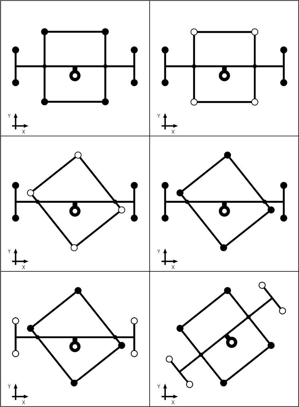
Actuation sequence for turning the robot
2.3. Fixation System
According to the considerations made earlier, and given that the robot has to move over a ferromagnetic surface, we have chosen a permanent magnet-based fixation system. As pointed out earlier, these types of fixation elements are safer in case of system malfunctions than other options - such as electromagnets or vacuum-based fixation elements - since none of these other methods can guarantee that the robot will not fall when a total loss of energy supply occurs.
The selected magnetic fixation system consists of NdFeB magnet shells with electromagnetic coils inside them which permit the system to cancel the magnetic field and, consequently, unfix the feet from the surface by generating magnetic fields opposed to those of the permanent magnets. This results in a very simple and effective means of achieving the fix-unfix actuation. In addition, there is another reason to choose this type of strategy based on the robot's operation: as mentioned above, grit blasting can generate a lot of ferromagnetic metallic dust and particles that will have a tendency to accumulate and remain attached to the magnets. The demagnetizing action, used as part of the robot movement operation, permits the elimination of stray particles from the magnets in a cyclic way. Otherwise, they would accumulate and render the magnets and the system unusable. This characteristic was important in choosing a legged robot over a wheeled one as - in this last case - it would be very difficult to demagnetize the wheels at any time without risking the robot becoming detached from the surface. A further advantage of this implementation is that the electromagnets within the permanent magnet shell can also be polarized to produce a magnetic field that is aligned with that of the permanent magnets, thus increasing the attraction and grip forces when necessary.
3. Electronics And Control
For any robot or automated structure to perform a task, a control system implemented over a certain type of electronics determines the sequences of actuations and the responses to the different signals provided by the sensors or the commands of users. This is no different in the case of a grit blasting robot. That is, to carry out the task of blasting, the robot needs to monitor its sensors, which provide information on its own kinematic and dynamic state, its location on the ship's hull and the surface quality achieved. Using this information, it needs to calculate in real-time the correct configuration of its actuators in order to perform the task assigned to it. In other words, the robot must achieve the appropriate kinematic configurations to allow it to move following a specific path and, in particular, a specific blasting head path. In fact, as the speed at which the head moves determines the quality of the stripping process, it needs to be able to follow a specific blasting head path at a particular speed, which must be adapted depending on the characteristics of the surface to be stripped.
The size and weight of the compressors needed for grit blasting, and the grit itself, are too heavy to carry onboard the robot without ending up with it becoming overburdened. Therefore, the most sensible thing to do would be to leave the infrastructure needed to generate the blast shot on the ground. A special hose is used to bring the grit jet to the blasting nozzle, which is onboard the robot, and moves with it. Likewise, from the point of view of the robot's energy requirements and actuation, an autonomous and independent robot solution should be found. This solution would carry on board the robot the equipment needed for supplying compressed air to the pneumatic actuators, with enough batteries to power the necessary electrical and electronic equipment. Again, the weight involved in this solution would be high and would make the robot more cumbersome and harder to handle. Here, we have chosen to design a system based on two hardware blocks: a robotic structure that moves along the hull transporting the blasting head and a base station that comprises all of the hardware on the ground required for providing energy, i.e., compressed air for the pneumatic actuators and compressors for producing the pressurized blasting shot. The base station is linked to the robot through two hoses (one with a blasting shot and the other with compressed air), an electrical power line and a control line.

Hardware involved in the control and operation of the robot. The left side of the image shows the base station devices while the right side shows the different actuators and sensors on the robot.
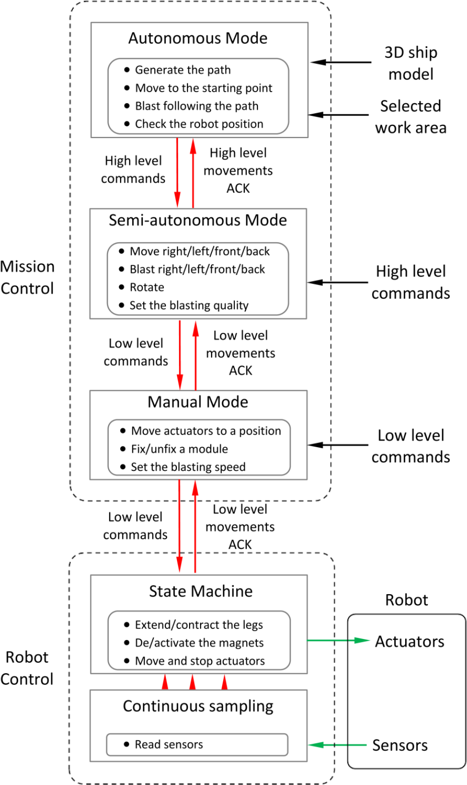
Schematic representation of the control system, which can be split into the robot control subsystem and the mission control subsystem
Thus, taking into account that there will be a physical connection between the robot and the ground, a decision was made to design the robot control system as a layered structure that is divided into two main parts: a robot control system, onboard the robot, which monitors the sensors and makes real-time decisions regarding the status of the actuators; and a mission control system, located at a base station on the ground, whose function is to permit the interaction with the operators, perform the necessary path planning required to cover the area to be blasted, and monitor the surface quality achieved using the information received from the cameras. As indicated above, these two control subsystems are joined together through a communications line. Fig. 5 displays a schematic representation of the different hardware elements involved in the control system and the operation of the robot. From another point of view, a schematic of the layered control system employed is presented in Fig. 6. As noted before, this control system can be split into a mission control subsystem and a robot control subsystem. These two different control substructures are explained in detail in the following subsections.
3.1. Robot Control Subsystem
In terms of electronics, the robot control subsystem is based on an electronic unit designed and developed specifically for this task. The core of this circuit is a PIC24HJ256GP206 microcontroller designed to work in industrial environments. It communicates with the mission control subsystem through an RS485 bus to receive operating instructions and to send information from the sensors. Among its responsibilities are the supervision of the hardware circuitry for the control of the actuators and the conditioning of the signals and information from the sensors.
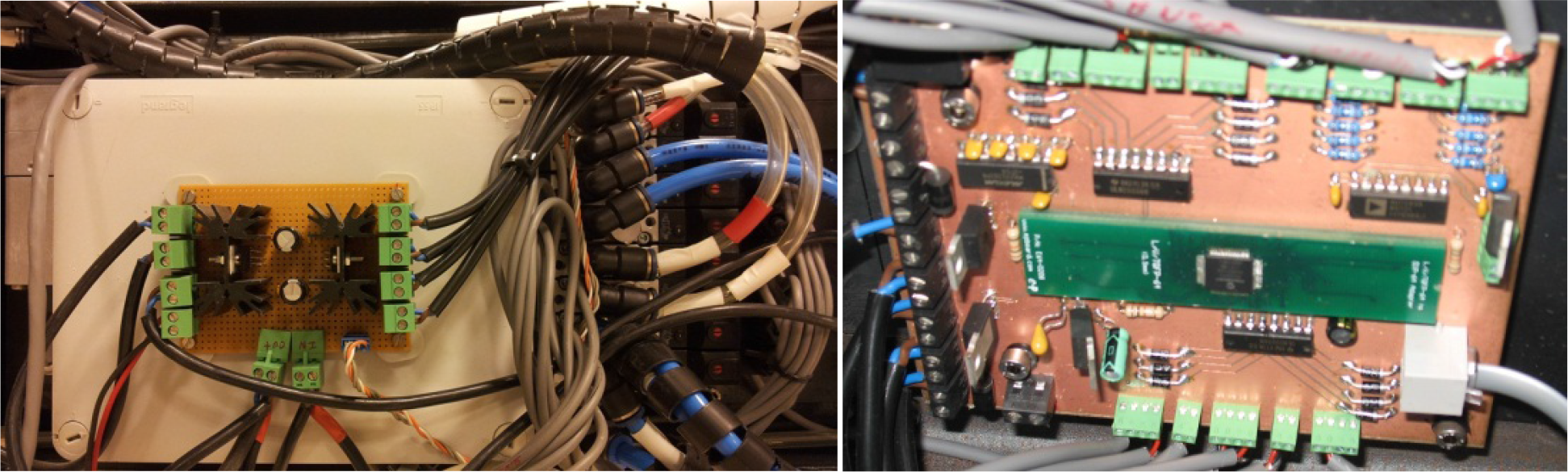
Pictures of the robot control subsystem hardware. The left image shows the box containing the electronic board and on its cover can be seen the heat sinks of the H bridges; to the right hand side of the image, we can see the electrovalves for controlling the pneumatic actuators. The right image shows the electronic board of the robot.
Two kinds of actuators may be found in the robot: pneumatic actuators that change the kinematic configuration of the robot and coils in the magnets of each leg. The pneumatic actuators are driven by solenoid valves, which are essentially low power inductive loads. Low power Darlington transistor nets based on ULN2003 IC's and free-wheeling diodes are used to drive these valves. In addition, there is a proportional valve for the control of the blasting head motion speed, which is controlled by an analogue voltage proportional to the desired output. This voltage is generated by an AD724CMOS monolithic amplified digital-analogue converter. Finally, the coils of the magnets are also essentially inductive loads, but of higher power. They are used to cancel or strengthen the magnetic field of the magnets by forcing currents through these coils in the right direction. For this purpose, full H-bridges of TLE5205 transistors are used. Some images of the hardware involved are presented in Fig. 7.
The system comprises four types of sensors: linear sensors, which measure the position of the pneumatic actuators and allow the real-time acquisition of the robot's kinematic configuration; a triaxial accelerometer that measures the local gravity and is used to estimate the spatial orientation of the robot and, thus, improve the estimate of the robot's position on the ship's hull provided by a cricket-based positioning system; and finally, video cameras for controlling the quality of the blasted surface and helping to position the robot.
The linear sensors and accelerometers provide analogue voltage signals that are conditioned and then read directly by the microcontroller's 10-bit A/D converter. The information from the cameras as well as the positioning information provided by the cricket mots is not processed on board, instead being sent as-is to the base station.
The robot control subsystem is a simple finite state machine which acquires data from the sensors cyclically. For instance, the linear sensors are sampled at 100Hz with a minimal use of the microcontroller because these samples are obtained using the analogue to digital converter hardware of the microcontroller. This hardware produces an interrupt when the sample is obtained and the software only has to save the values to a variable. Moreover, if the robot is moving its actuators, the interrupt checks whether any actuator is reaching its target position in order to stop them. The state machine receives commands through the RS485 line and, after checking them, generates the low-level actions. An example of this is when the robot receives a command to move the lower module to a new position. In this case, the microcontroller unfixes the magnets of the lower module, employing the H-bridge. Afterwards, the robot waits for at least half second so as to guarantee that the current is flowing into the coil of the magnets and, thus, that there is no adhesion force left so that the legs of the module can be retracted smoothly. Next, the microcontroller activates the valves in order to retract the legs and move the lower module in the desired direction. When the actuators achieve the desired position, the microcontroller stops the motion, activates the brake and start the sequence to fix the lower module to the hull. This sequence basically implies activating the magnets of the lower module and, at the same time, extending the leg actuators. Again, after a few moments to guarantee that there is no current in the coil of the magnets, the legs are contracted so as to reduce the distance to the hull without any risk of unfixing the magnets from the surface.
The robot control is basically an on/off control of the actuators because we employ on/off pneumatic valves, which do not allow for any PWM modulation. The program of the microcontroller calculates the velocity of each actuator to switch off the valve at the exact moment needed so as to make the actuator stop with precision at the desired position. Only the grit blasting head actuator is controlled by a proportional pneumatic valve, which can be used to control the grit blasting head speed through a simple PID controller.
In addition, the robot control subsystem checks the status of the robot and sends alarms to inform the base station. In the particular case where the robot detects a strong vibration, an emergency stop is activated. This implies stopping any movements, activating all the magnets to obtain the maximum adhesion force and starting the routine to fix the unattached modules. This emergency stop can also be activated by an operator by pressing an emergency switch. The signal thus generated produces a high priority interrupt in the microcontroller which activates the emergency stop routine.
3.2. Mission Control Subsystem
The mission control subsystem, which is physically located in the base station, interacts with the operator thereby allowing him to control the robot, calculates the paths for the blasting head, and monitors and controls the blasted surface quality achieved. The hardware used for this purpose is a standard PC with an RS485 interface for communication with the robot control subsystem as well as an appropriate input for the information sent from the quality control video cameras. In addition, out of the different possible alternatives that can be found in the literature for positioning [23] and [24], we have chosen a cricket system [25] that provides the position of the robot on the hull using information from the time of flight of simultaneously emitted radiofrequency and ultrasound signals. This system comprises a series of modules - or mots - one of which (a listener mot) is placed on the robot blasting head. The rest of the mots (emitter mots) are placed on the ground along the length of the ship. In this system, the higher the density of mots, the greater the precision of the position information provided. The position estimation obtained from the cricket system is augmented by information coming from odometric measurements of the motion of the robot, the robot's orientation in space obtained by the triaxial accelerometer, and the hull's geometry contained in the digital hull model used by the mission control application.
The mission control is based on three hierarchical layers which correspond to the three different operating modes, as shown in Fig. 6. The lower layers are employed by the upper layers and each layer is accessible to the operator through a graphical user interface (Fig. 8).
In this interface, the user can choose between the three operating modes: manual, semi-autonomous and autonomous. In the first one, the manual mode, the user can set the state of each robot actuator manually in real-time and thus control the robot's kinematic state and its movement over the ship's hull with incremental movements. This layer provides functionality to the layers on top of it and, when managed directly by the operator through its graphical user interface, it is mostly used for testing and maintenance operations or else to remotely control the blasting head for very particular applications. In addition, this layer is responsible for handling communications with the robot and periodically checking that there are no active alarm conditions.

Graphical user interface of the manual, semi-autonomous and autonomous modes

Graphical user interface of the autonomous mode. The work area is selected over the 3D model of the ship hull and this layer generates a path to completely grit-blast this area.
In the second mode of operation, the semi-autonomous mode - which corresponds to the second control layer of the mission control subsystem - the user chooses the direction of travel of the robot over the hull, and the mission control application automatically generates the required sequence of commands to the actuators that perform the requested movement. This layer basically decomposes these high-level commands into low-level commands, which are sent to the lower layer. The blasting action is user-selectable and the robot continues to move in the selected direction until the user provides a stop command
In the third mode, the autonomous mode, the user interactively selects the area to blast in a graphical interface that shows the ship's hull. This is achieved by providing four or more points that determine a polygon that corresponds to the borders of the area to be blasted (see Fig. 9). The mission control subsystem automatically generates the appropriate paths to accomplish the blasting of the selected area, calculates the corresponding commands for the robot, and monitors it using the location system while following those paths in order to correct possible deviations. This subsystem contains a quality control module that uses the information from the cameras to determine the surface finish achieved. It controls the speed of the blasting head to adapt to the operational conditions and, if required, commands the robot to repeat the blasting in areas that do not reach the desired surface finish.
It is important to note here that the selection made by the user of the area of the ship hull to be blasted results in a hull surface portion that is usually warped. The automatic trajectory planning algorithm takes into account the warped nature of the selected surface and inserts the required rotation commands between linear translations of the robot to cover the entire surface portion. Furthermore, it also takes into account openings in the hull of the vessel and forbidden blasting zones, and excludes them from the automatic path generation process, adapting the trajectories as needed. This layer, after automatically generating the path, sends the high-level commands to the lower layer. Next, it waits for the acknowledgment that informs it that each high-level command has been carried out.
The blasting speed is directly related to the initial state of the surface to be treated and inversely related to the surface finish quality achieved. When the blasting speed increases, the surface quality decreases, and vice versa. The mission control application tries to find an optimum where the blasting speed is maximized while ensuring the desired finish standards. This minimizes the total time required for the mission and its related costs.
A detailed description of the operation of the mission control subsystem is presented in the second example of the next section.
4. Operation examples
In this section, we will present some examples of the operation of the robot. The objective of these runs is to show the operation of the robot and to tune its different subsystems, as well as the whole robot. To this end, this section is divided into three parts, each devoted to a different aspect. First of all, some examples are presented where the robot moves over a horizontal surface. Their purpose is to present the system as a whole and test the different motion strategies of the robot without having to worry about the attachment or the location problem. These tests also helped to tune the local robot control parameters and strategies.
After this, the next subsection addresses the location problem, i.e., determining in real-time the location of the robot on the surface on which it must operate so that the mission control module can make it work autonomously. These experiments were carried out in a more realistic environment that suffered most of the electromagnetic shielding and interference problems typical of shipyards and ships where most surfaces are made of steel. The mission control module was tuned during these tests.
Finally, we have addressed the attachment problem in an experiment in which the robot must operate while moving over a vertical surface, which is the worst condition for magnetic attachment strategies. It was during these tests that the optimum attachment/release strategy for the different operations of the robot has been determined. This last experiment involves the whole robotic system and, as such, can also be considered a validation experiment for the robot as a whole.
4.1. Low-level module tuning
As indicated above, the first example involves moving over a horizontal, flat and non-ferromagnetic surface. These tests have been carried out in order to check the different subsystems of the robot and to tune the parameters of the local or low-level control system, except for the magnet control parameters. In this first example, we wanted to ignore the attachment problem and, therefore, the magnets were changed for rubber tipped legs in order to increase the friction coefficient. This also shows the versatility of the semi-modular design of the robot, which allows the magnets to be changed for rubber tips or suction cups in order to allow the system to deal with hull surfaces other than ferromagnetic ones. Obviously, since magnetic fixation is not considered, the routine to fix or unfix of one module to the ground is different from that employed on ferromagnetic surfaces. When the modules extend their legs to contact the ground, it is the weight of the module on the rubber legs and the friction between the ground and the rubber tips that fix the module. Conversely, a module becomes unfixed from the surface just by contracting its legs. Figs. 10 and 11 display the behaviour of the robot when performing translation and rotation operations. The sequence of motions needed to perform these operations and, consequently, the actuations that are necessary, have been described in section 2. Suffice it to say that after several trials in which the parameters of the low-level controller were adapted, the robot performed both the linear movements that are necessary to move up and down the hull and sideways and the rotational movements necessary for turning and/or adapting to the curvature of the hull flawlessly for different motion speeds and sequences.
Sequence of images of the robot performing all the movements required for grit blasting several bands

The robot rotates on a horizontal surface
4.2. Positioning system and mission control
In order to make the system autonomous, a mission control module has been developed, as explained in section 3. The objective of this module is to be able to supervise the operation of the robot when working for long periods of time without human intervention. In order to achieve this, it is obviously necessary for this module to be aware of the exact location and orientation of the robot, as well as of its current state. This state is obtained from the sensors in the different components (see the diagram in Fig. 5) that allow the mission control subsystem to know in which position each of the actuators is at any time, as well as other variables such as its speed or, in the case of magnetic coils, whether they are active or not and whether their activity complements the magnets or cancels them. The orientation of the robot with respect to the hull is obtained, as indicated in the electronics section, by means of a triaxial accelerometer. Finally, the position on the hull is obtained using a cricket-based [25] system. These positioning systems triangulate the distances from a listener module, placed on the grit blasting head of the robot, to some beacon modules placed in the environment. The idea is to place several beacons near the ship all along its length at the shipyard where the ship is grounded for grit blasting. In the experiment presented here, the beacon modules were placed on tripods near the operating surface and facing the robot, in order to approximate reality. This scenario is displayed in Fig. 12, where two beacon modules as well as the robot placed on the vertical surface and the base computer can be seen. This setup has been used to test the position and orientation determination capabilities of the system in order to ascertain its validity for the niche it is supposed to cover, as well as to validate the mission control subsystem in terms of being able to generate the appropriate trajectories and guide the robot along them without mistakes.
The procedure followed prior to blasting a given area of the surface is for the operator to mark four or more points on the graphical user interface (GUI) of the mission control subsystem, which displays the 3D model of the ship hull as displayed in Fig. 9. These points determine the working area of the robot. To reliably obtain the position of the robot on the ship hull during operation, and before starting the blasting process, the listener module must be placed on four or more points of the hull and these points must be selected by an operator on one of the screens of the user interface that shows a real-time video of the robot and the surface to be blasted. Using this information, the mission control software and, in particular, the cricket system, can calibrate itself and better adapt to the particular characteristics of the environment. Once the working area has been determined, the mission control software - which contains a 3D representation of the surface to be blasted - calculates the trajectory of the robot and the movements of the blasting head needed to fully blast the area. This trajectory is then translated into command sequences for the low-level control module that take into account the turns the robot must make in order to compensate for the curvature of the hull or to avoid forbidden areas. The operation of the robot is constantly monitored and any deviations in the position of the robot and/or blasting head which are detected are corrected appropriately. In order to avoid any errors induced by electromagnetic noise - which is always present in industrial environments - the position of the blasting head is filtered, taking into consideration past positions and the constraints on its movement.
For the purpose of illustrating the results obtained, an image of the mission control GUI in a given instant of the robot's operation is displayed in Fig. 13. It is split into two sections: the world of the robot and the real world. In both sections we can see the four points that determine the working area of the robot in this case and the path followed by the grit blasting head (painted yellow).
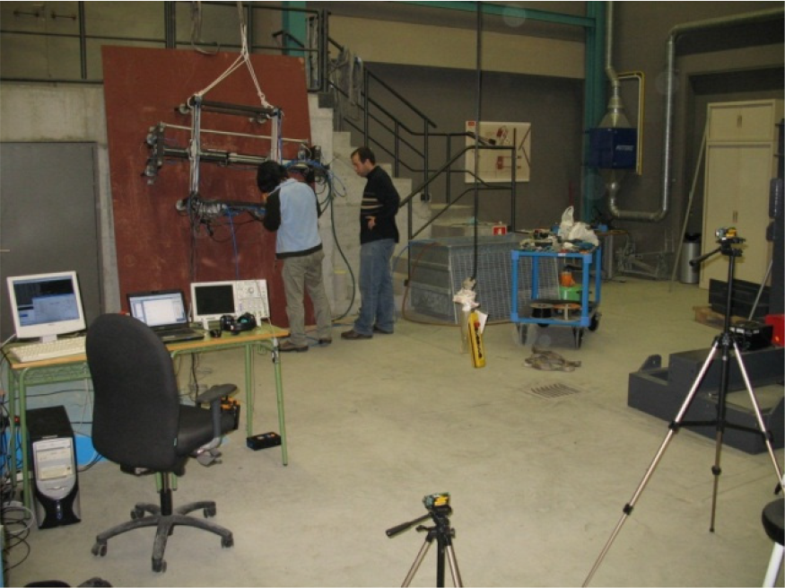
Experimental environment for testing the robot. We can see the steel plate to which the robot is attached, the computer running the mission control subsystem and two tripods holding two cricket beacons.
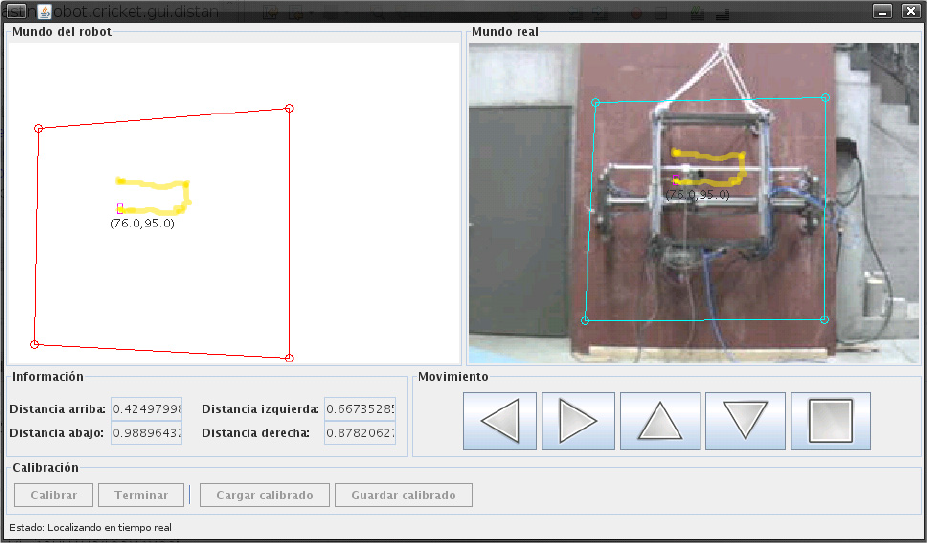
Graphical user interface showing the work area of the robot and the path of the grit blasting head at a given instant of time during the operation of the robot
4.2. Robot attachment and operation on a vertical surface
The last set of experiments was carried out on the environment presented in the previous subsection containing a ferromagnetic surface placed vertically with respect to the ground (see Fig. 13). This ferromagnetic surface is a 10mm steel ship hull plate (2.0 × 2.8 m) with a shop primer and, therefore, it is a realistic environment. In addition, this environment represents the worst condition that the robot will experience in terms of attachment, as the only way to prevent the robot from sliding is through friction between the magnets and the steel plate. The achievement of a high enough frictional force using elements such as the magnets and steel surfaces - which present quite low friction coefficients - requires a very strong normal force from the magnets that can compensate for a robot weight of around 80 kg, as well as for vibrations and other undesired effects using just half of the magnets (as those are the only ones available when the robot is moving). On the other hand, the size of the magnets must be contained in order to make the robot easy to handle. Consequently, we chose to use a magnet that provides a normal attraction force of around 1000N, which is enough to fix the robot to the vertical plate when one module is detached. Nonetheless, when there are a lot of vibrations, the robot - even with the four magnets that provide a joint normal force of about five times the robot's weight - may slide down the surface. Therefore, for safety reasons, the coil inside the magnets is used to increase the attraction force in the magnets placed in the fixed module before unfixing the other module and until this module is again attached. We found that in this way, the robot never detaches or slides down the surface, even under high vibrations. To further improve on this situation and reduce the moments acting on the magnets, a few seconds after the magnets of one of the modules of the robot are attached to the hull their legs are contracted so as to reduce the distance between the hull and the robot's centre of mass. This also ensures that all of the magnets are really in contact with the hull, as it may present imperfections that would leave one leg in the air if all the other legs are extended. In the images showing the operation of the robot on the steel plate - and again, for safety reasons - the robot always operates while linked to a crane by two ropes. However, these ropes are not in tension and do not provide any support to the robot.
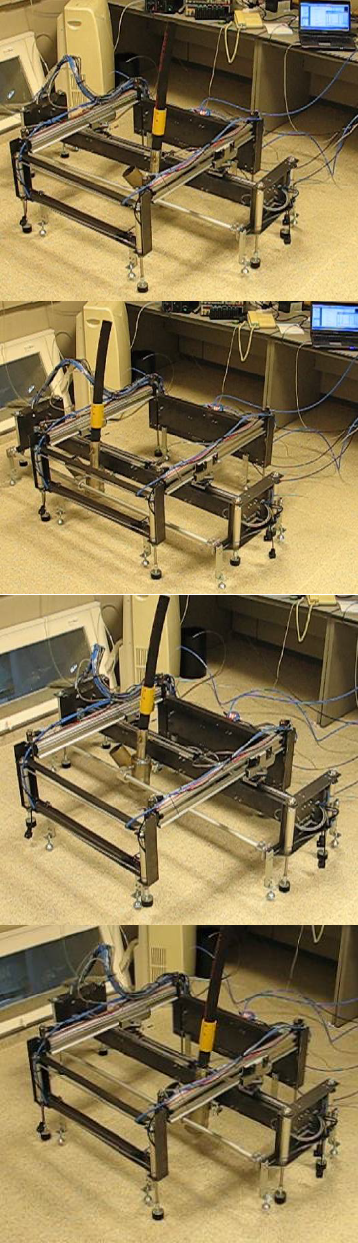
A sequence of pictures showing the typical grit blasting operation is displayed in Fig. 14. Basically, and as explained in section 2, the robot moves the grit blasting head to strip a horizontal band and then the lower module descends the width of the strip to permit the stripping of a new band (each pair of pictures that are positioned side by side show the beginning and end of a strip. We have omitted all the strips between the first one in the top two pictures and the last one within the same position of the top module shown in the middle). When the actuators of the top module reach their end stroke, the lower module cannot continue its descent, which is the case for the pictures in the middle. At this point, the bottom module is attached to the surface to allow the top module to move down all the way, reattach itself and thus permit the lower module to continue descending and stripping new bands with the grit blasting head (as shown in the bottom two pictures). The whole sequence is carried out in less than 40 seconds. In the images of Fig. 14, we have intentionally included the stairs beside the steel plate so as to provide a reference of size and distance.

Sequence of pictures showing the typical procedure for grit blasting a surface when moving vertically
Fig. 15 shows the robot performing a horizontal displacement. In this case, the first picture on the left shows the initial state of the robot, which had been working on the right side of the steel plate. Thus, the robot fixes the lower module to the plate and displaces the top module towards the left. Next, it fixes the top module to the plate and displaces the bottom one leftwards. It will continue doing this until it reaches the new vertical area to be blasted. The limited size of the plate does not allow for greater displacements to be shown.

Robot performing a horizontal displacement
Finally, Fig. 16 shows a more complicated manoeuvre in this test environment - a 90° rotation, as explained in section 2. The robot takes 30 seconds to carry out all the necessary movements. In this case, starting from picture a, the robot first moves the sliders of the top module opposite to each other in order to rotate the bottom module. After this, it fixes the bottom module and rotates the top one by moving its sliders opposite to the previous case and then fixing the bottom module. It continues to perform this sequence until the final rotation angle for the blasting head strip is achieved.
In summary, the robot operates successfully in realistic environments and conditions even when complex movements are required. It is able to move forwards, backwards or sideways and it is able to turn appropriately. The mission control subsystem provides the sequences of actions that the robot must carry out to this end based on the location information provided by the cricket system, the state information provided by the different sensors on the robot and the area defined by the operator as the area to be blasted on the 3D model of the ship hull.

90° rotation manoeuvre of the robot carried out in 30 seconds.
5. Conclusions
This paper describes the design and implementation of a robot for grit blasting ship hulls, including its architecture and its control system. In terms of architecture, the robot is based on two modules that move with respect to each other in order to endow the system with the capability of performing translations and rotations over curved hulls. These two modules are attached to the hull through hollow permanent magnets with coils inside them. This setup provides for a very simple actuation mechanism for detaching the robot legs from the surface as well as for increasing the attachment force when required. An additional advantage of this approach in terms of grit blasting is that it makes it very easy to get rid of any ferromagnetic dust that may become attached to the magnets during operation, since whenever a leg detaches the magnetic structure is demagnetized by the coils.
A layered control system has been created for this robot. There are four control layers, one of them on the robot itself and three on the base station. This control structure allows the robot to operate in manual, semi-autonomous and autonomous or unsupervised modes. In fact, in the unsupervised mode, the operator simply provides the points defining a polygon corresponding to the area that the robot must operate over and the higher level mission control system or layer calculates the trajectory the robot and its blasting head must follow in order to adequately blast the area to the specified quality. This trajectory is then converted into robot actions by the lower layers, taking into account the 3D nature of the hull and inserting the appropriate turns. These actions are finally converted into actuations by the lower level control layer and these are carried out and monitored in order to make the adjustments that are deemed necessary to successfully finalize the task.
The different systems that make up the robot - as well as the whole robot - have been implemented as a prototype and tested in a realistic environment and the results were completely satisfactory. It is now the object of current and future work to produce a final version of the robot that is able to operate for extended periods of time in real shipyard environments.
Footnotes
6. Acknowledgments
The authors would like to acknowledge the support of the Navantia shipyards of Spain in this project, especially in the tests and experiments performed, as well as their permission for publishing the results. We would also like to acknowledge the support of the Xunta de Galicia through project 09DPI012166PR