
Abstract
Surmounting obstacles during continuously climbing in a complex environment is an important issue for pole-climbing robots. An obstacle-surmounting strategy is presented for a pole-climbing robot. The force and moment applied on the pole-climbing robot in static status were analyzed, and the analysis of pole-climbing robot’s upward vertical climbing was conducted. The climbing execution has four steps: loosening the lower gripper, curling up, striding forward, and clamping the upper gripper. To obtain the information of obstacle crossing accurately, the obstacle-surmounting conditions were analyzed in detail. We modeled the striding linkage with thickness and obtained the Denavit–Hartenberg coordinates of each vertex. The model of the grippers with thickness was proposed and the Denavit–Hartenberg coordinates of each vertex of the grippers were obtained. Then single-step negotiating an obstacle and multistep negotiating an obstacle were proposed. Experiments were conducted to verify the effectiveness of the obstacle-surmounting strategy.
Introduction
Pole-climbing robots (PCRobots) can be used to carry out high-risk tasks for human beings in hazardous situations, such as inspection, 1,2 supervision, 3,4 and maintenance. 3,5 Due to their importance in aerial work, PCRobots have been attracting interests of the researchers.
PCRobots have been built and implemented, such as HyDRAS, 5 RiSE V3, 6 Climbot, 7 Shady3D, 8 and BiPCRs. 9 These robots are mainly studied in the respects of structure and climbing gaits. Specifically, HyDRAS was a serpentine robot that consisted of a serial chain of actuated universal joints for wrapping around pole-like structures. 5 The methods and considerations for selecting the optimal design parameters (module length, module diameter, helical pitch, and allowable range of motion) were presented for the given task of climbing pole-like structures. RiSE V3 was developed for dynamical, high-speed climbing of uniformly convex cylindrical structures. The climbing machine included novel linkage designs for its legs to propel the body forward during climbing locomotion. 6 Climbot was a biped climbing robot with five joint modules connected in series and two special grippers mounted at the ends. Three climbing locomotions in trusses were proposed based on modular and bioinspired robots. 7 Shady3D had three motive degrees of free, which moved along the three-dimensional (3D) truss structure with a fixed section shape. 8 A novel binary approximating method was proposed to compute the graspable region for a BiPCR and to generate the 3D workspace of a manipulator with a constant orientation. 9,10 A tethered winding-styled soft rod-climbing robot could move on vertical, horizontal, or tilted rods with corners. It consisted of two winding actuators and a telescopic actuator to improve the locomotion efficiency. 11
For these robots, the self-continuous climbing is a necessity as the operators may not be able to see the next target to be grasped by the robots all the times. However, how to surmount obstacles for PCRobot during continuously climbing in a complex pole-type environment is a challenging issue.
Dynamic path planning had been presented to generate collision-free strategies for PCRobots moving in obstacle-cluttered environments. Chen et al. designed a mathematic model to make BiPCRs overcome obstacles for transition. 12 A feasible single-step collision-free climbing mode for BiPCRs was proposed, which could avoid obstacle-crossing gait. 9 A grip planning strategy was also proposed to generate collision-free grip sequences based on global path planning. 13 The collision-free path planning method was based on energy optimization. And the collision-free path points were generated following the artificial potential field and sampling searching analysis. 14 An autonomous obstacle avoidance method was suggested for a robotic manipulator based on an improved RRT algorithm. 15
These designs 13 –15 are only applicable to the truss-type environment where there are multiple alternative paths to be selected to avoid obstacles. If there are obstacles that the robots cannot evade, the above methods are not applicable. Some researchers tried to solve this situation by improving the structure or adding additional equipment. Xu and Jiang designed a mechanical structure for a bilateral-wheeled robot to overcome obstacles of semi-surrounding structures. 16 Lee and Chu developed a three-modular obstacle-climbing robot. The winch mechanism was set to assist the controller to climb obstacles, and the robot controller coordinated the three modules as well as the winch to climb obstacles. 17 In some cases, it is impossible to add additional equipment to assist obstacle crossing. However, the obstacle can be surmounted by changing the gait of the climbing robot. Therefore, this article focuses on the obstacle-surmounting gait of the PCRobots.
In this article, an obstacle-surmounting strategy was proposed for a PCRobot. An obstacle-surmounting model was firstly built up for computing the enclosed space of five-bar linkages. And the surmountable conditions were proposed. Then single-step negotiating an obstacle and multistep negotiating an obstacle were proposed. Lastly, experiments were conducted with PCRobot to verify the effectiveness of the obstacle-surmounting strategy.
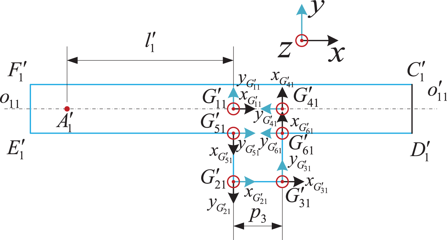
PCRobot architecture
3D model of PCRobot
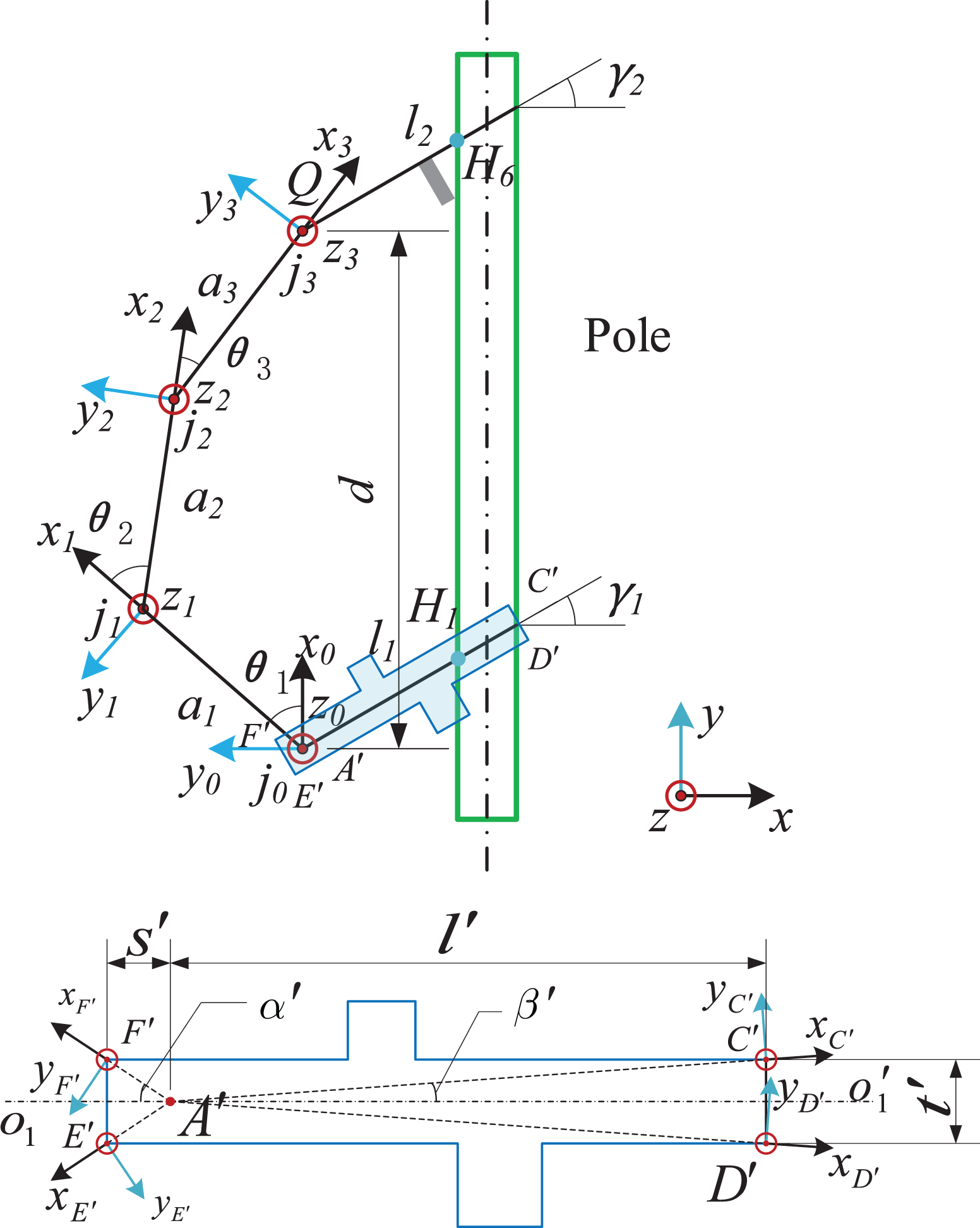
The 3D model of PCRobot is shown in Figure 1. It consists of five-bar linkages of

3D model of the pole-climbing robot. 3D: three-dimensional.
The flipping-over gait of PCRobot is decomposed into two stages: flip and stride, which are described in Qiaoling et al. 18
The mechanical structure of PCRobot prototype is shown in Figure 2. Two grippers g
1and

Mechanical structure of PCRobot prototype. PCRobot: pole-climbing robot.
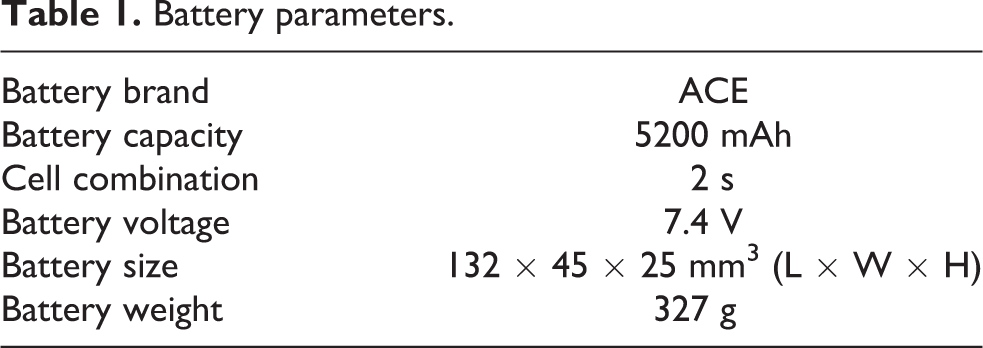
Battery parameters.
Denavit–Hartenberg parameter model
In Figure 1, a
0 and g
1, a
4 and g
2 are fixed connections, which are represented by l
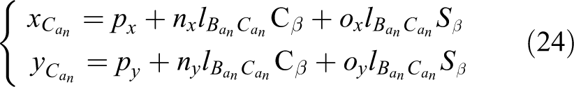
1 and l
2, respectively. The fixed angle

D-H coordinate system of PCRobot. D-H: Denavit–Hartenberg; PCRobot: pole-climbing robot.
The Denavit–Hartenberg (D-H) coordinate system of PCRobot is established as shown in Figure 3. The coordinate system of j
0 is represented by x0
–z
0. The coordinate systems of j
1, j
2, and j
3 are established in turn, such as x
1–z
1, x
2–z
2, and x
3–z
3. The parameters are shown in Table 2.
The kinematics analysis and inverse kinematics solutions
Parameters of D-H coordinate system of PCRobot.

D-H: Denavit–Hartenberg; PCRobot: pole-climbing robot.
Upright and inverted postures
In the process of continuous climbing, the robot’s posture is alternately “upright posture” and “inverted posture,” as shown in Figure 4. The upright posture is defined as the state of g 1 below g 2, otherwise defined as an inverted posture.
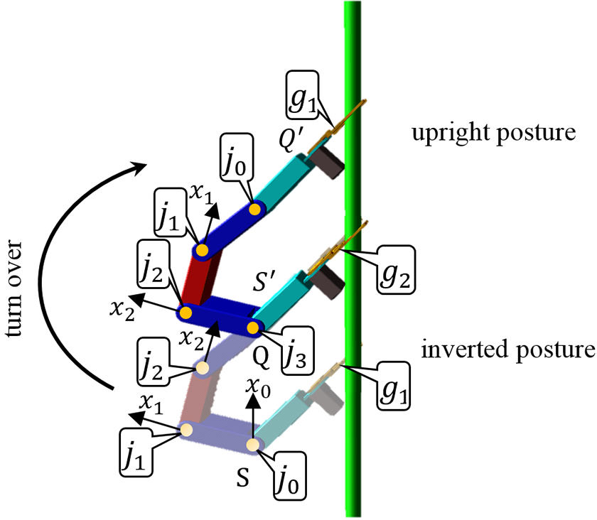
Upright and inverted postures of PCRobot. PCRobot: pole-climbing robot.
In the upright posture, the order of the four joints in the counterclockwise is j
3, j
2, j
1, and j
0, as shown in Figure 4 “upright posture.” The D-H coordinate system of PCRobot has been derived elsewhere.
18
When the robot turns over, its posture changes to the inverted posture. At this time, the order of the four joints is changed to j
0, j
1, j
2, and j
3, as shown in Figure 4 “inverted posture.” The D-H coordinate system of PCRobot has been adjusted accordingly.
Modeling and analysis of the obstacle-surmounting
Static analysis of PCRobot
When the robot is in the posture shown in Figure 4, the robot is in static status on the pole. Under static situations, the force of the robot is balanced. Figure 5 illustrates the lateral view of the forces and moments applied on the PCRobot. The equilibrium status of the forces applied on the robot meet the following conditions Lateral view of PCRobot force and moment in static status. PCRobot: pole-climbing robot.


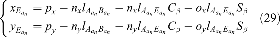
where
Since the mechanism of the robot is axisymmetric and the rod is symmetric, the following conclusions are drawn:
From equation (3)
From equation (4)
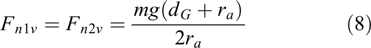
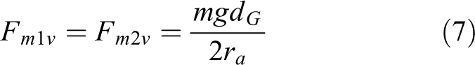
From equations (1), (7), and (8)
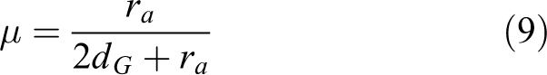
The static friction coefficient can be expressed as a function of the position of the robot’s mass center and the radius of the pole. When the radius of climbing poles of different materials is fixed, the decrease of friction coefficient means the increase of dG , so as to keep the robot in equilibrium.
Dynamic analysis of PCRobot
The joints of PCRobot are driven by the steering gears. In the process of vertical climbing, the performance of the steering gears determines the dynamic performance of PCRobot. The weight of the robot determines the gravity of the robot, which is a key factor in the design of climbing robot. The prototype of PCRobot weighed 1.07 kg. According to the force analysis results, TBS2701 steering gear was adopted. The parameters of the TBS2701 are listed in Table 3. The TBS2701 has a maximum rotation angle 270°, in which j 0, j 1, j 2, j 3 can be conveniently located at any position.
Main parameters of the TBS2701 steering engine.

For upward vertical climbing, the climbing execution is divided into four steps: loosening the lower gripper, curling up, striding forward, and clamping the upper gripper. Take the reversal process from the inverted posture to the upright posture as an example, the climbing control process is as follows: the steering gear s 0 rotates to loosen the lower gripper g 1; the steering gears s 1, s 2, s 3, and s 4 rotate to curl up at a fixed angle; the steering gears s 1, s 2, s 3, and s 4 rotate to stride forward according to the calculated angle (see Qiaoling et al. 18 for details), and the steering gear s 0 rotates to clamping the upper gripper g 1.
A serial control is adopted for the execution of four steps. The time t to complete a climb is

where tl
is the time to complete the loosening,
The servo system of steering gears is controlled by PWM. The reference signal period of the steering gear is 20 ms, and the pulse width is 1.5 ms. Each rotation time is fixed. The steering speed of the steering gears depends on the difference between the starting angle and the target angle. The greater the difference, the faster the steering gears turn. As approaching the target angle, the rotation slows down. In the process of control, if the speed of the steering gears is too fast, the steering gears are easy to shake and stall. Therefore, the following methods are used to reduce the speed of the steering gears: when the steering gears rotate at a large angle, the program sets it to several small angle progressions and decelerates by delaying the program in the progressive process.
The experimental results show that the minimum controlling time of the steering gears is 2 s. In the loosening and clamping steps, only s
0 works, so set tl
= 2,
Analysis of obstacle-surmounting conditions
Enclosed space of five-bar linkages
The enclosed space R of five-bar linkages is defined as the closed area enclosed by linkages of the robot and pole. R is a hexagonal region, and its six vertices are, respectively, H
1, H
2, H
3, H
4,

Enclosed space R of five-bar linkages and the convex polygon K. (a) Enclosed space R of five-bar linkages. (b) Convex polygon K.
The surmountable conditions are as follows:
Condition 1: R and K are independent of each other.
Condition 2: let P(x, y) ∈ K, P(x, y) ∈ R.
Let


Set

Position relationship between robot and obstacles. (a) K inside R. (b) K outside R.
In fact, if the position relationship between K and R satisfies condition 1, as long as any point P(x, y) of K is limited within R, Figure 7(b) can be excluded.
Assume the position relationship between K and R satisfies condition 1 and K
1 is selected as P(x, y). K
1 is defined on the climbing pole, so condition 2 can be simplified as “whether point K
1 is located between


where l is the length of
If equations (13) to (15) are established, condition 2 is satisfied. If conditions 1 and 2 are satisfied, then K

Change of R in the process of robot turning.
Influence of linkages thickness on R
The actual robot structure has a certain thickness. The effect of thickness on R needs to be considered. The space occupied by the thickness of the robot structure should be removed from R.

As shown in Figure 6(a), each linkage is described by only one segment, and the two ends of the segment are the joints. The coordinates of the joints can be directly solved by using the D-H model of the robot linkage structure mentioned in Qiaoling et al.
18
Because of the thickness of the robot structure, the dynamic description of
Specifically, if the robot is composed of n bar linkages and the i-th linkage is surrounded by mi
segment, then the set of edge segments of all bar linkages is

where
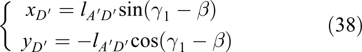
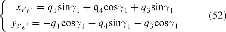
Modeling of the striding linkages with thickness
To obtain the dynamic model of
The striding linkages of PCRobot include a
1, a
2, and a
3. The main entities of a
1, a
2, and a
3 are shown in Figure 10(a). To simplify the analysis, the contour of the thickness area of the striding linkage is taken as a rectangle, as shown in Figure 10(b). Let

Model of striding linkages (a 1, a 2, a 3) with thickness. (a) Main entities of a 1, a 2, a 3; (b) Approximate rectangle of the striding linkage with thickness; (c) Solution of vertex coordinates by virtual link method.
As shown in Figure 10(b),

Then the length of

In this article, the size of the striding linkage is symmetrical (
There are three striding linkages (a
1, a
2, and a
3) in the PCRobot. In the following, a
2 is taken as an example to analyze the coordinates of the striding linkage, which is the same as the analyses of a
1 and a
3. Transformation matrix MB
from x
0–z
0 to x
2–z
2 can be obtained as shown in equation (21),
19
as shown in Figure 11.
A and B in D-H coordinate system of PCRobot. D-H: Denavit–Hartenberg; PCRobot: pole-climbing robot.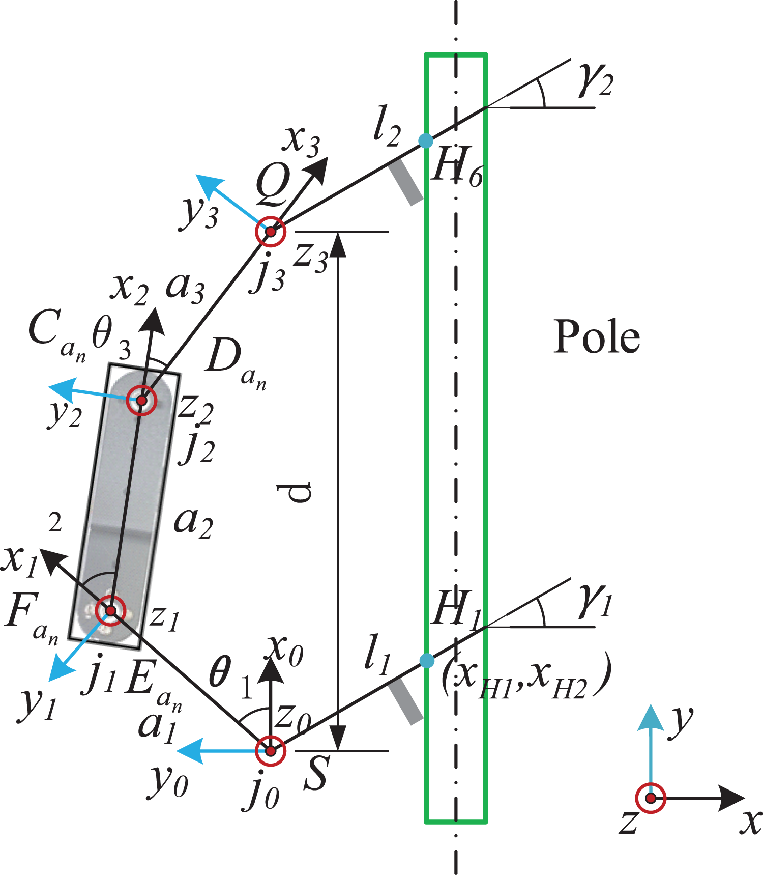

where
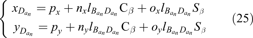
D-H parameters of virtual link structure

D-H: Denavit–Hartenberg.

Set

According to the definition of coordinate system matrix,
18
the origin coordinate (
D-H parameters of virtual linkage structure

D-H: Denavit–Hartenberg.
The virtual linkage method is also used to solve the coordinates of
D-H parameters of virtual link structure
D-H: Denavit–Hartenberg.
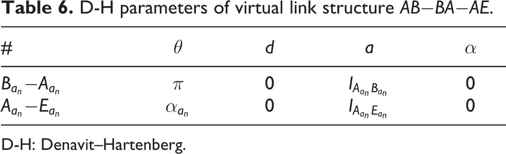
According to Table 6, TA and TE are obtained as followed

Due to

According to the definition of coordinate system matrix,
18
the origin coordinate (
D-H parameters of virtual link structure

D-H: Denavit–Hartenberg

The contour of the striding linkage with thickness can be described as

The coordinates of
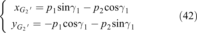
Modeling of the grippers with thickness
The shape of the robot’s grippers is irregular. One gripper is with a battery, and the others are not. To simplify the analysis, multiple rectangles are combined to describe the contour of the grippers, as shown in Figure 9.
Modeling of
the gripper with battery
As shown in Figure 12, the gripper with battery is composed of the support, the steering gear, and the battery. The vertices of three regions are solved, respectively.
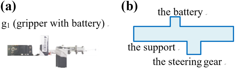
Model of the gripper with battery: (a) physical structure and (b) outer contour.
(1) Vertex coordinates of the support
The four vertices of the support are defined as
Model parameters of the support of the gripper with battery.
According to the geometric relationship in Figure 13, equations (32) to (35) can be obtained


Set
The virtual linkage method is used to solve the coordinates of
D-H parameters of virtual linkages in the support.

D-H: Denavit–Hartenberg.


(2) Vertex coordinates of the steering gear
The four vertices of the steering gears are defined as

Model parameters of the steering gear of the gripper with battery.
The virtual linkage method is used to solve the coordinates of
D-H parameters of virtual link structure in the steering gear.

D-H: Denavit–Hartenberg.


(3) Vertex coordinates of the battery
The four vertices of the steering gears are defined as

Model parameters of the battery of the gripper with battery.
D-H parameters of virtual link structure in the battery.

D-H: Denavit–Hartenberg.


The coordinates of the vertices of g
1 are calculated by the method of virtual linkage. These coordinates are used to describe the edge segments of g
1 as

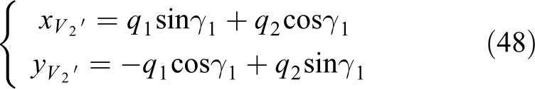
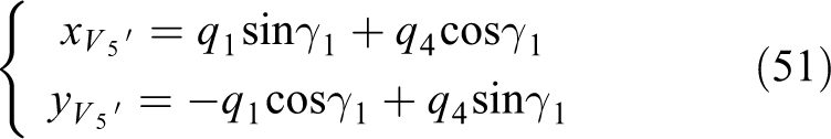
Modeling of g 2
As shown in Figure 16, g 2 is composed of the support and the steering gear. The structure of the gripper without battery is consistent with the support and the steering gear of the g 2.

Model of the gripper without battery.
The virtual linkage method is used to solve the coordinates in Figure 17. Set

Model parameters of the support of g 2.
The four vertices of the steering gears are defined as
Model parameters of the steering gear of g 2.
The solution process described in this section is the same as the one in section vertex coordinates of the support.


The coordinates of the vertices of g
2 are calculated by the method of virtual linkage. These coordinates can be used to describe the edge segments of g
2 as

Analysis on grippers in upright and inverted posture
There are differences in the structure of g 1 and g 2. g 1 is the structure with the battery and g 2 is the structure without the battery. When the robot is in the upright posture, g 1 is the lower gripper as shown in Figure 19(a). And when the robot turns over, g 2 is the lower gripper in inverted position, as shown in Figure 19(b). During the stride locomotion (see Qiaoling et al. 18 ), the shape of R′ is constantly changing as shown in Figure 8. In the sections Modeling of the striding linkages with thickness - Modeling of the grippers with thickness, the virtual link method can be used to calculate the vertex coordinates of each part. The virtual linkage method is based on D-H coordinate, so the vertex coordinates obtained can be updated in real time according to the linkage locomotion.

Shape of
Set


Decision condition
The internal space enclosed by the fuselage structure is
Condition 1:
Condition 2: let P(x, y) ∈ K, P(x, y) ∈
Obstacle-surmounting control
Single-step negotiating an obstacle
To facilitate the analysis, K is set as a rectangle. Its vertices are K
1, K
2, K
3, and K
4, as shown in Figure 20. hk
is the height of K, wk
is the width of K, dk
is the length of

Obstacle parameters.
Set the coordinate systems of o be x
0–y
0. Then the coordinates of K
1, K
2, K
3, and K
4 are

The stride distance

Due to the limitation of robot structure, there are the minimum and the maximum of a stride. Set
In the process of negotiating, the vertex coordinates of the linkages are calculated by the virtual link method. The attitude of the robot is adjusted continuously so that the surmountable conditions are satisfied between the linkages of the robot and the boundaries of the obstacle. Finally, the robot strides over the obstacle in one step.
Multistep negotiating an obstacle
In some scenarios, robots cannot cross obstacles in one step, even if the obstacle is the same as shown in Figure 20. If the robot climbs up and stops under the obstacles,
Multistep negotiating an obstacle consists of three steps: climbing down, climbing up, and negotiating.
Firstly, the robot climbs down the pole for m times, as shown in Figure 21(a). Set the step backward be dm
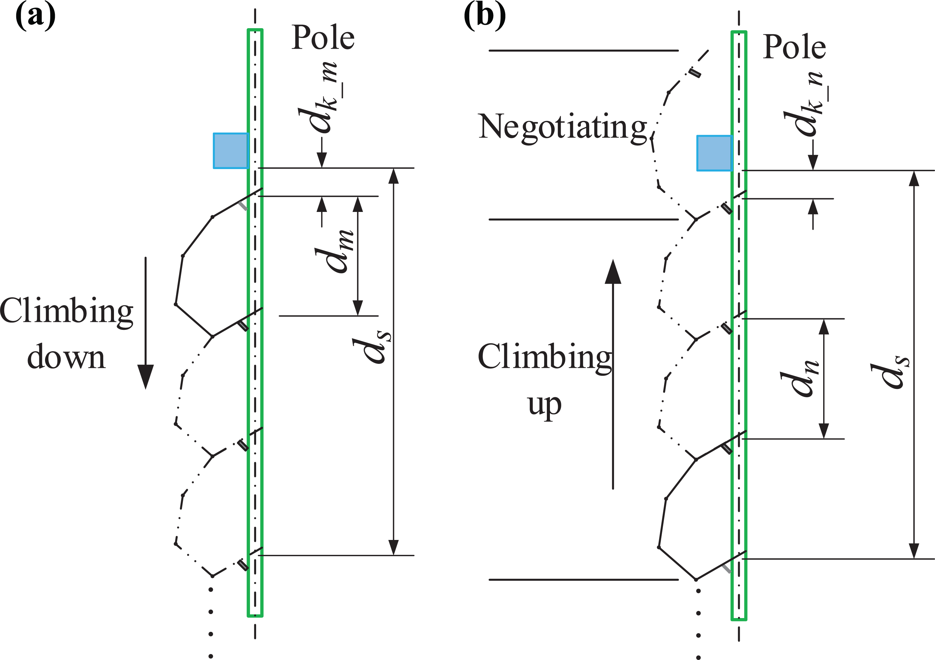
(a) and (b) Multistep negotiating an obstacle process.


Secondly, the robot climbs up the pole for n times, as shown in Figure 21(b). Set the step upward be dn


Thirdly, the robot negotiates the obstacle in the form of one step.
Although the reduction of

Critical situation.
lh
is the length of the gripper.


Obstacle-surmounting control process
Based on the single-step and multistep negotiating an obstacle, the robot can realize the obstacle-surmounting. Suppose that the obstacle moves relative to the robot, the velocity of the robot is v, and the velocity of the obstacle is vk .


where
From equation (77)

tk
can be equal to t (e.g.

In addition to the surmountable condition, the obstacle-surmounting also needs to satisfy equation (79).
The robot’s obstacle-surmounting process is shown in Figure 23. Firstly, the camera c samples the image information, dk and vk of obstacles. Through vk identifies whether the obstacle is stationary or moving, so that static obstacle crossing and dynamic obstacle crossing are performed, respectively. The obstacle size is extracted. According to the above D-H coordinate transformation, we can judge whether the surmountable conditions are satisfied. Next, judge whether the single-step negotiating an obstacle condition is satisfied. If it is satisfied, single-step negotiating an obstacle will be executed; otherwise, multistep negotiating an obstacle will be executed.
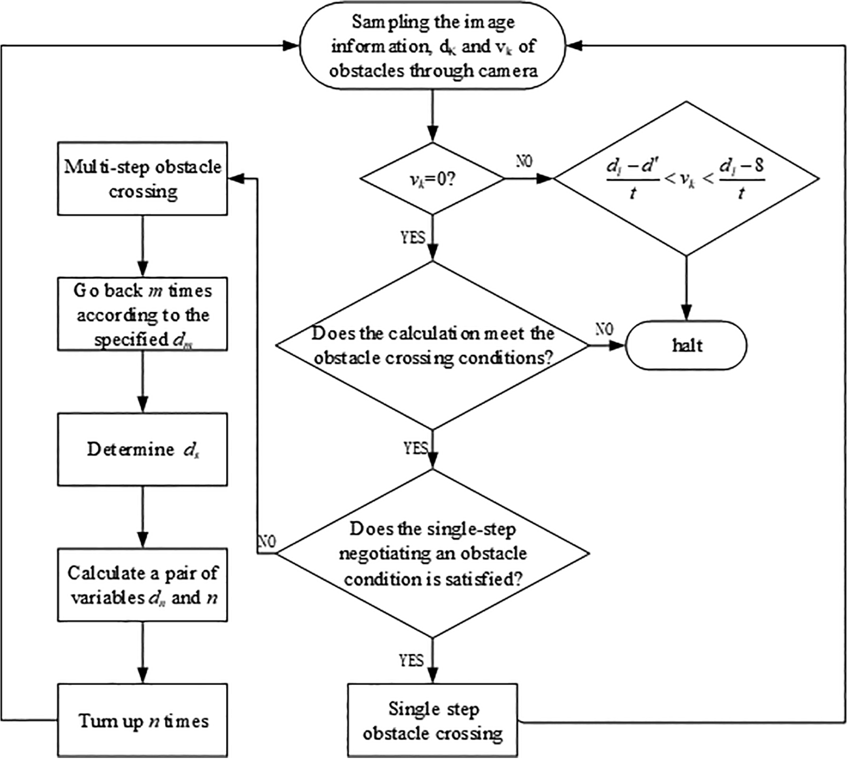
Dynamic obstacle-surmounting control flow.
Prototype and test
We designed PCRobot prototype as shown in Figure 2. The prototype weighed 1.07 kg (including a battery) and it was 60 cm long when fully extended. The specific size is shown in Table 11. Constrained by the robot’s current structure, a single span of the robot was 8 to 23 cm. The parameters of existing climbing robots are listed in Table 12. PCRobot is much lighter than other robots. Its shape is similar to a line. In terms of volume, PCRobot is much smaller than the other robots in Table 12. The size of the smallest robot 22 in Table 12 is 72 × 50 × 22 cm3, while that of PCRobot is 60 × 7.1 ×5.4 cm3.
Dimensions of PCRobot components.

PCRobot: pole-climbing robot.
Comparison of climbing robots.

To enable the robot to sample the angle relative to the ground in real time, MEMS three-axis accelerometers (MPU6050; InvenSense Inc., Sunnyvale, CA, United States) were equipped on
The size of the obstacle negotiating an obstacle
Set the lateral view of the obstacle crossed be rectangular. The test records the size of the lateral view of the obstacle that can be negotiated. The green area is the size of the lateral view of obstacles that PCRobot can negotiate in Figure 24. It shows that the width of the lateral view of the obstacle is inversely proportional to its height. The maximum height was 13.5 cm, and the maximum width was 15.5 cm.

Size of the lateral view of the obstacle that can be negotiated.
Anti-sliding load capacity test of PCRobot
The anti-sliding load capacity of the robot was tested on wooden and PVC climbing pole, respectively. The robot was controlled in three states. Posture 1, the upper and lower grippers grip the pole; posture 2, the lower gripper grips the pole and the upper gripper is released; posture 3, the upper gripper grips the pole and the lower gripper is released. In each state, a downward pull force is applied at s 1, s 2, s 3, and s 4 steering gears to test the anti-sliding load capacity of the robot. The force gauge is Handpi Instrument, HP–500, division value 0.1 N. The results of the anti-sliding load capacity are listed in Table 13.
Anti-sliding load capacity of PCRobot.

It can be obtained from Table 13 that the friction coefficient of iron relative to wood material is small, so the anti-sliding load capacity of PCRobot on iron climbing pole is reduced. For the same material climbing pole, the different cross section will also affect the anti-sliding load capacity of the PCRobot. For the gripper of PCRobot, the anti-sliding load capacity of the robot on the square climbing pole is strong.
Experiment of single-step negotiating the obstacle
Experiments were done to test the single-step and multistep negotiating an obstacle, respectively, and the dynamic obstacle-surmounting.
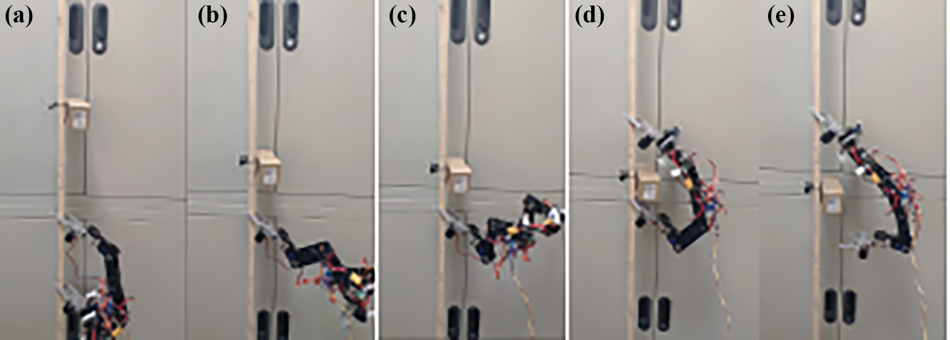
The cross section of climbing pole was rectangular 2.7 × 1.7 cm2. The cube obstacle was 6 × 4 × 13 cm3. PCRobot was placed in the initial position, and the distance between the upper gripper and the obstacle was
The robot strides over obstacles in one step, as shown in Figure 25(a) to (d).

(a) to (d) Single-step negotiating the obstacle.
Experiment of multistep negotiating the obstacle
The distance between the upper gripper and the obstacle was

(a) to (l) Multistep negotiating the obstacle.
Experiment of dynamic obstacle-surmounting
The distance between the upper grippers and the obstacle was

In the experiment, a simple structure of the pulley was used to control the obstacle to slide down at
(a) to (e) Dynamic obstacle-surmounting.
Conclusions
In this article, the obstacle-surmounting strategy of the climbing robot is proposed. This strategy can solve the problem that the robot cannot stride over obstacles in one step in some scenarios. Firstly, the obstacle surmounting model of five-bar linkage in closed space is established. Secondly, the surmountable conditions were proposed. Thirdly, single-step obstacle crossing and multistep obstacle crossing are proposed. In the process of obstacle surmounting, the camera is used to collect the information of obstacles, and the single-step or multistep obstacle crossing gait is determined according to the sampling information. The strategy does not need to add additional external auxiliary equipment and can cross obstacles on the only way. The strategy proposed in this article can be used as a reference for climbing robot to surmount obstacles.
Footnotes
Declaration of conflicting interests
The author(s) declared no potential conflicts of interest with respect to the research, authorship, and/or publication of this article.
Funding
The author(s) received no financial support for the research, authorship, and/or publication of this article.
Supplemental material
Supplemental material for this article is available online.
References
Supplementary Material
Please find the following supplemental material available below.
For Open Access articles published under a Creative Commons License, all supplemental material carries the same license as the article it is associated with.
For non-Open Access articles published, all supplemental material carries a non-exclusive license, and permission requests for re-use of supplemental material or any part of supplemental material shall be sent directly to the copyright owner as specified in the copyright notice associated with the article.