
Abstract
This paper focuses on the stair-climbing problem for a tracked robot. The tracked robot designed in this paper has the ability to explore stairs in an unknown indoor environment, climbing up and down the stairs, keeping balance while climbing, and successfully landing on the stair platform. Intelligent algorithms are proposed to explore and align stairs, and a fuzzy controller is introduced to stabilize the tracked robot's movement during the exploration. An inexpensive Kinect depth sensor is the only equipment needed for all the control modes. Finally, experiments illustrate the effectiveness of the proposed approach for climbing stairs.
1. Introduction
Because of the surge in urbanization, many people worldwide are migrating from rural to urban areas, meaning high-rise buildings are needed in cities. However, it is a big challenge for mobile robots to patrol these indoor environments. For robots to handle movement tasks inside buildings, an appropriate robot platform needs to be developed for stair-climbing and cliff-avoidance. Stair-climbing becomes the crucial ability for patrolling robots.
Shape-shifting robots [1–6], legged robots [7], and flexible snake robots [8] are the hardware platforms currently being focused on for indoor-environment search and rescue [9, 10]. Recently, legged robots and tracked robots have been the most used type in stair-climbing tasks. Tracked robots have the advantages of excellent stability, flexible structure, and low terrain pressure; therefore, they can adapt well to stairs or obstacles. A design of variable track configurations was presented by Jeehong Kim in VCTV-1 and VCTV-2 [11, 12] for the purposes of maximizing adaptability to steep paths and minimizing the rotational resistance. VCTV-3 [13], which was the first single-tracked mechanism with planet wheels, showed good adaptability to stair-climbing tasks. Pandora [14] used a double-track mechanism with dual-attack angles for both indoor and outdoor environments. Inheriting advantages from the variable-track vehicle VCTV-3, the rescue robots Micro-VGTV (Inuktun Corp.) and Packbot (iRobot Corp.) [15] have been presented in the 21st century. However, in these tracked robot systems, there is no mechanical separation of transforming and driving. Therefore, it is difficult to derive the appropriate angle for surmounting obstacles and climbing stairs. Thus, tracked robots have been made with separation or double-tracked systems in recent years. Wang [16] developed a separated-type tracked robot for mine search and rescue, which is equipped with a pair of swing arms. The transformations of the arms helps robots surmount obstacles.
Under kinematics and dynamics constraints, stair-climbing becomes a complicated process for tracked robots. Lacking a sense of equilibrium in manipulation during stair-climbing, the tracked robot easily drifts from a straight heading, resulting in a high risk of tumbling down the stairs. Liu et al. and Hou et al. [3, 6, 16, 17] designed a mathematical model for the physical structure of track robots. However, the model was too simple to control the robot precisely on stairs. Analyses of stair-climbing and obstacle-climbing have been presented in [2, 4, 8]. In [4], the CG (centre of gravity) kinematics mode was proposed for climbing up an obstacle for a robot equipped with a pair of swing arms; however, the analysis of stair-climbing was deficient in [4]. An analysis of stabilization of stair-climbing was presented in [2, 6]; however, downstairs locomotion was not included.
To complete the stair-climbing task, the use of sensors is important. CCD cameras or range-finder sensors are the most commonly used devices in tracked robots. But these sensors are either expensive or depend on time-consuming image processes [18]. The Kinect depth sensor consists of an infrared laser projector combined with a monochrome CMOS sensor, which can capture video data in 3D under any ambient light condition. In addition, the sensing range of the depth sensor is adjustable. It can capture the distance between the target and the sensor in dark or complex environments [19]. Currently, autonomous mobile robots are necessary to offer a diversity of types and functions. Hence, this paper mainly focuses on the functionality and practicality of self-made tracked robots, which can autonomously explore stairs, climb up and down stairs and calibrate their position in relation to stairs. Depending on distance information captured by the Kinect sensor, the designed tracked robot is able to extract and analyse the stairs' characteristics and autonomously complete the stair-climbing tasks. Moreover, the exploration mode, control mode, alignment mode, climbing mode, and landing mode are designed to achieve the tasks of identifying stairs, moving upstairs and moving downstairs.
2. Tracked robot platform and stair components
2.1 Reconfigurable structure
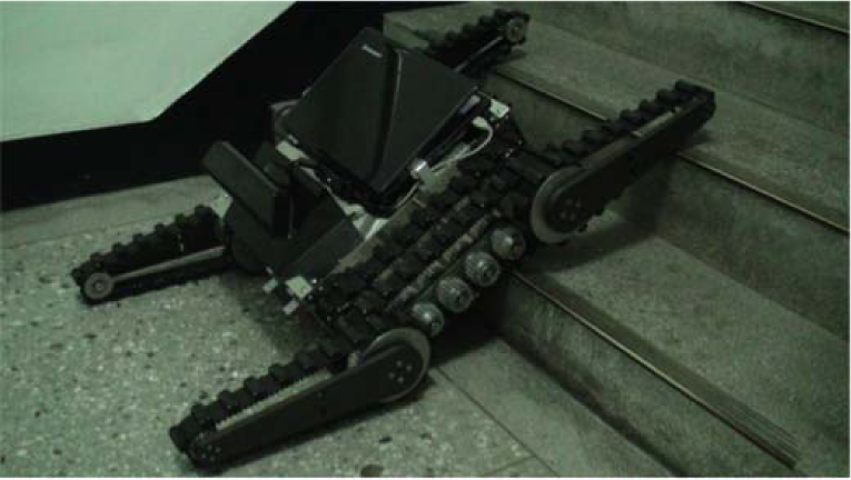
The robotic platform (Figure 1) consists of six tracks, in which the front and rear track pairs are articulated with two solid axles and the other two tracks are assembled with the lateral sides of the robot body. The front and rear track pairs are independently driven by a 150 W servo motor for the purpose of geometry changes; both of the lateral-side tracks are also driven by a 150 W servo motors. The ratio of the reduction gears connected to the front and rear track pairs is 1:50, and the gear's ratio of the lateral sides of the robot body is 1:30. The tracked robot is 35 kg, 790 mm long, 570 mm wide, and 180 mm high. Both the front and the rear arms are each 190 mm long. The maximum speed of the robot is 1 m/s. The drivers (CSBL920) of each motor communicate with RS232/RS485 in a cascade. By defining a leader driver, the robot connects the controller to the motors for sending and receiving control information. The controller uses a computer with i5 CPU, 4 G RAM, and a 2010VC++ development environment.

Structure of the tracked robot
2.2 Kinect sensor
Kinect sensors can supply 8-bit VGA resolution (640*480 pixels) with a Bayer colour filter and monochrome depth-sensing video stream in VGA resolution (640*480 pixels) with 11-bit depth, which provides 2,048 levels of sensitivity. They have a practical ranging limit of 1200–3500 mm and can maintain sensing ability in approximately 500–6000 mm. The sensor has an angular field of view of 57° horizontally and 43° vertically, and the motorized pivot has up to 27° up and down tilt [19].
2.3 Stair components
Stairs are mainly incorporated with stairways and stair platforms. Stairway components and their related key parameters are shown in Figure 2. A stair angle is an important factor related to walking easiness and climbing efficiency. θ1 (Figure 2(a)) is defined as the angle of stairs. The stair dimension is defined by the riser height h1 and the tread width d1. The stair length w1 is in general 1500 mm to 2000 mm. l s represents the centre line of stairs and the dashed line (Figure 2(b)) represents the edge of the staircase. In general, a step of a staircase inside a building is around 200 mm-350 mm deep, 120 mm-180 mm high, and probably more than 1800 mm wide. Accordingly, the front arm of the track robot was designed to be 190 mm long to make sure the robot was able to climb 180-mm-high steps. That is, taking advantage of the design of the 190 mm-long front arms, the robot is able to hook the edge of the first step with the rubber blocks, as shown in Figure 1(a), and, therefore, can be raised and pushed on the stairs by the big torque motors if the robot moves near enough to the stairs.

Stair components
3. Control algorithms
3.1 Concept of control design for exploring and climbing stairs
Constrained by track robots' kinematics and dynamics, stair-climbing is a complicated task and there is little research analysing robots' climbing behaviours. The autonomous tracked robot developed here is expected to explore stairs, move forwards facing the stairs, and change geometry configuration for climbing and landing safely. The steps of exploring and climbing stairs are as follows:
The basic track configuration for easily exploring stairs is to keep the front and rear track arms up (Figure 3). The front and rear arms rotate to the stair's angle θ1 when the robot is ready to climb the stairs. (Figure 4(a)). The track configuration changes to the straight type (Figure 4(c) and Figure 4(d)) when the robot is on the stairs. (Figure 4(b)). The robot changes the configuration of the front arm until the arm touches the floor at the moment when the robot reaches the top of the stairs (Figure 4(e)). The front arm rotates to the stair's angle (Figure 5(b)) when the robot moves forwards and is then extending a little over the step surface. (Figure 5(a)). The track configuration of the robot changes to the straight type (Figure 5(d)) when the robot is on the stairs (Figure 5(c)). The robot changes the configuration of the front arm until the arm touches the platform (Figure 5(e)).

Track configuration for exploring stairs (basic track configuration)

Variable track configurations for climbing upstairs

Variable track configurations for climbing downstairs
The steps of climbing stairs are depicted in Figures 3–5, which show the capability of the tracked robot to adapt to stairs by changing its geometry configuration. In this paper, we expect the tracked robot to be able to autonomously explore stairs in an unknown environment and effectively complete the stair-climbing task using the developed intelligent control modes. For this purpose, five modes are developed, as shown in Figure 6. The exploration mode is expected to locate stairs only depending on the Kinect depth information, which is used to detect the features of the edge of the staircase. Then the robot autonomously moves toward the stairs while maintaining room to climb safely in control mode. Maintaining the robot's movement parallel with the stairs' centre line l s is an important issue when climbing. The tracked robot has to face the stairs. This will be done in the alignment mode. The purpose of the climbing mode is to supply the robot with enough friction force to climb stairs. Finally, the landing mode gives a function for landing.

Functions of the tracked robot
3.2 Control strategies of upstairs locomotion
3.2.1 Exploration mode
Exploring stairs in an unknown environment is a critical issue. Analysing captured depth information can assist the robot to detect the features of the edge of staircase and to get find the proper direction towards the stairs. The steps to determine stairs' features are as follows:
Determine the stairs' features (Step 1): The top left of the pixel pixel(0, 0) is set to the original point, and the pixel on the xth column and the yth row is represented as pixel(x, y). Removing the pixels that are outside the sensing limitation of the Kinect, and searching the pixels in the interval D down ≤|pixel(x, y-1)-pixel)|| ≤ D up , we can determine the features of the edge of the staircase and give them a value of “1”; we give other features a value of “0”. The features of the edge of the staircase are the targeted stairs' features (TSFs) in this paper. According to the standard values of the tread width, D down and D up are respectively chosen as 250 mm and 350 mm. The pseudo code for searching TSFs is shown in Figure 7.

Pseudo code for searching TSFs for locomotion upstairs
Extract the edge of staircase (Step 2): However, the TSFs are not perfect after Step 1, as shown in Figure 8. The pixel “1” means the TSFs, and the empty pixels 1 describe other features. This step intends to identify the stairs from the scattered TSFs. A searching box (Figure 9) moves from left to right, and puts the first TSF's point pixel(i, j) on the first cell of the searching box. If the area of the box contains TSF points other than itself, the box moves towards the nearest feature point, which is the one next to the first cell. Then the searching algorithm goes on until the last TSF point pixel(k, l) is found. If not, the algorithm will be stopped, and then starts again on the next pixel. If the length of the segment from pixel(i, j) to pixel(k, l) is longer than 200 pixels (which is about one-third of horizontal pixel line), this segment is defined as the edge of staircase.
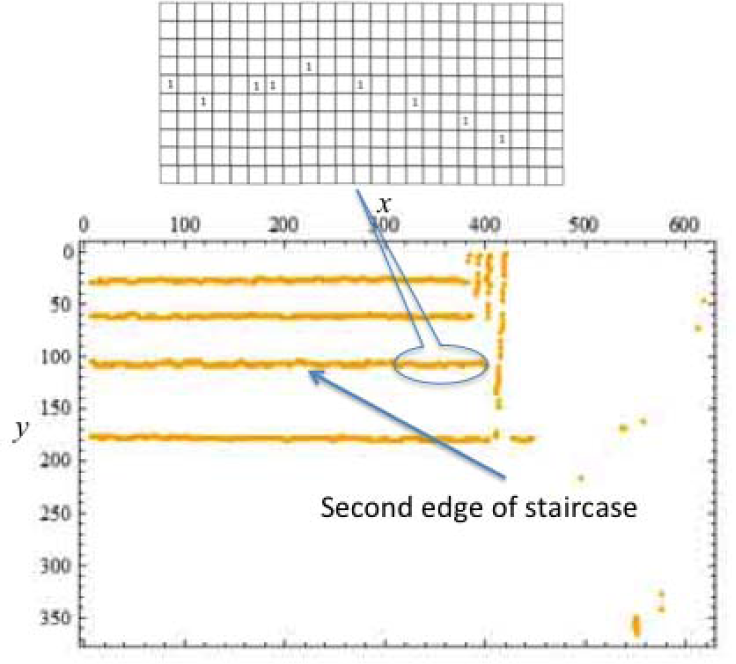
Feature points of the edge of the staircase after Step 1
In this method, the segment of the edge of the staircase can be interrupted in the range of two pixels if the dimension of the searching box is set to 3 × 4. Otherwise, if no segments exist in the frame, either there are no stairs or the tracked robot is still too far away from the stairs, and the tracked robot re-explores.
Determine the stairs' location (Step 3): Calculating an average of the pixel pixel(i,j) and the pixel pixel(k, l), we can obtain the centre point of the edge of the second staircase in the depth image. The centre point is used as the benchmark for determining the direction of the stairs for the tracked robot, as shown in Eq. (1).


Method of searching for the edge of the staircase
3.2.2 Control mode
This paper develops a fuzzy controller for the tracked robot to achieve the task of stably moving towards the stairs following the given direction, as shown in Eq. (1). The inputs of the fuzzy control are chosen as the depth d and the x coordinate (x c ) of the pixel stair2(x, y), and the outputs are the speeds of the left (v l ) and right (v r ) motors, which respectively drive the left and right tracks of the robot. The membership functions of the depth d and the coordinate x c are shown in Figures 10 and 11. The membership functions of the outputs are shown in Figures 12 and 13.
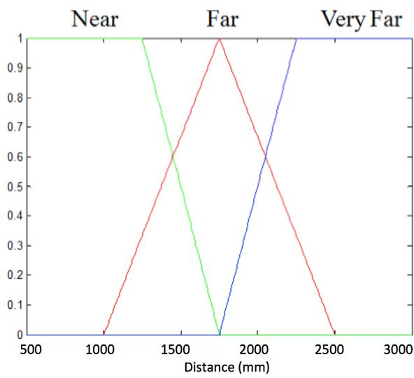
Membership functions of the distance d
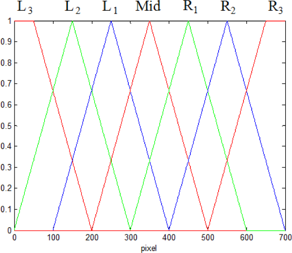
Membership functions of the coordinate x c
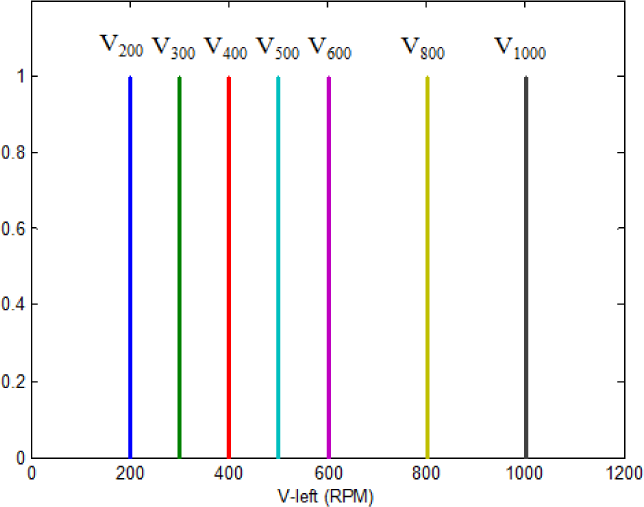
Membership functions of the speed of the left motor (v l )

Membership functions of the speed of the right motor (v r )
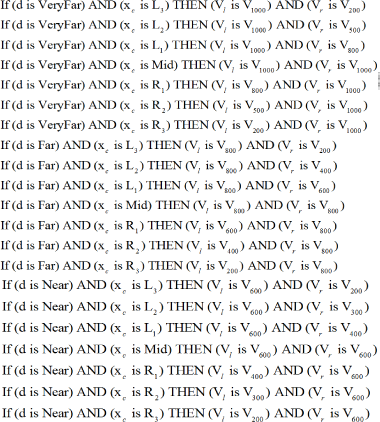
The fuzzy rule base is shown in Eq. (2).


Flowchart of the exploration mode and control mode
3.2.3 Alignment mode
At the moment when the tracked robot changes to the alignment mode, facing the tracked robot completely towards the stairs is essential to avoid slipping. In Figure 15, two blocks, block
l
and block
r
, are used to make sure that the robot's direction of movement is parallel to the stairs' centreline l
s
. The choices for the locations of the two blocks can be used on most of the stairs; each block contains 100 pixels. The equation for removing the disturbed pixels (d > 1800 mm) and averaging the remained distance information on the block is:


Detection of alignment in the alignment mode for upstairs locomotion
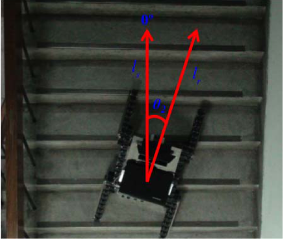
Angle between the centreline of the tracked robot and the stairs
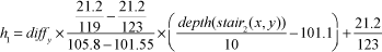
The other goal of the alignment mode is to calculate the stairs' angle θ1, as shown in Figure 2(a). Moving a 212-mm-high object between 555 mm to 1191 mm from the tracked robot, and measuring the distance and the corresponding number of the pixels of the object high in the image, we can obtain a dataset of the number of pixels and the real distance of the object, as shown in Figure 17. Then, through linearizing and formulating the dataset at the points 1015.5 mm and 1058 mm, which are around the area of the alignment mode, the linear relationship can be described as:


Linear relationship of the pixel's number and its real distance

Calculation of the angle of stairs for upstairs locomotion
3.2.4 Climbing mode
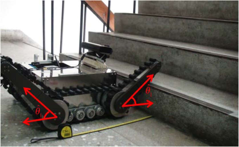
Before climbing stairs, the tracked robot changes its track configuration according to the estimated stairs' angle θ̂1, as shown in Figure 19. Afterwards, the tracked robot moves forward until the rear arms completely touch the ground (Figure 4(b)), and the robot changes to the straight type.
Track configuration before climbing upstairs
3.2.5 Landing mode
When the captured distance information of the centre of the last edge of the staircase stair last (x, y) is smaller than 350 mm, the tracked robot changes to the landing mode. In this mode, the robot moves forwards 750 mm, which at the value of 750 mm-350 mm is about two thirds of the length of the robot body, and it transforms the track configuration as shown in Figure 20. The angle of the front arms is −45° and the angle of the rear arms is maintained. While the tracked robot moves slowly forwards, the robot resumes the basic track configuration (Figure 3).

Track configuration before landing
3.3 Control strategies of downstairs locomotion
3.3.1 Exploration mode
There is no need to change any procedure for downstairs locomotion in this mode. To enlarge the vertical view of the stairs, the tracked robot changes the angle of the Kinect sensor to −250 (Figure 22); however, the searching area is shrunk. The pseudo code for searching TSFs for downstairs locomotion is shown in Figure 21, where d down is chosen as 250 mm.

Pseudo code for searching TSFs for downstairs locomotion

Angle change of the Kinect sensor: (a) sketch (b) real configuration
3.3.2 Control mode
The stair searching area becomes narrow when the tracked robot is engaged with the task of downstairs locomotion. Therefore, the control mode is simplified as a straight locomotion toward the pixel pixel c .
3.3.3 Alignment mode
Two blocks, Block l and Block r , on the floor are chosen for the alignment mode for the task of downstairs locomotion. The tracked robot can calculate the diff x by Eq. (5).

Detection of alignment for downstairs locomotion
3.3.4 Climbing mode
When the alignment mode is finished, the robot moves forwards until the robot's body overhangs the stair by 100 mm. Then, the tracked robot changes its track configuration according to the estimated stairs' angle θ̂1 before moving downstairs, as shown in Figure 24. Then, the tracked robot moves forwards until the rear arms completely touch the ground, and the robot changes to the straight type.

Track configuration before climbing for downstairs locomotion
Track configuration before landing for downstairs locomotion
3.3.5 Landing mode
As soon as sensing depth information of the pixel pixel(320,80) is smaller than 700 mm, the tracked robot slowly resumes the basic track configuration, as shown in Figure 25. It should be noticed that the depth of pixel(320,80) is always bigger than 700 mm in the climbing mode for the task of downstairs locomotion.
3.4 Overall system for stair-climbing tasks
Figure 26 shows the flowcharts of the tasks of upstairs locomotion and downstairs locomotion. One ne difference between them is the judgement condition in the climbing step for the landing mode. Both the climbing mode and the alignment mode are active in the climbing step.
4. Experimental results
4.1 Experimental environment and tracked robot's tasks
The step length, riser height, and tread weight of the stairs are 1800 mm, 170 mm, and 290 mm, respectively. The tracked robot is 2500 mm away from the stairs, as shown in Figure 27. The tasks of the tracked robot are as follows:
Search for stairs and move towards the stairs; Climb the stairs and keep balance; Land on the floor in upstairs locomotion and move forward; Turn back and search for stairs again; Move downstairs and keep balance; Land on the floor in downstairs locomotion and move forward.

Flowcharts of stair-climbing tasks (a) upstairs locomotion (b) downstairs locomotion
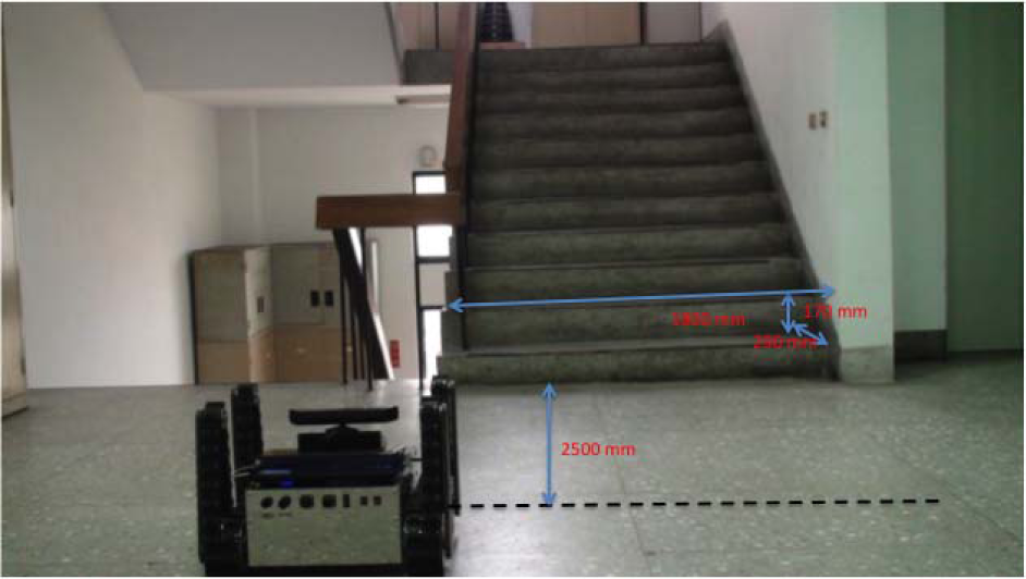
Experimental environment
4.2 Results
Figure 28 shows the movement while the tracked robot is under the exploration and control modes. Figure 28(f) shows that the tracked robot is not really close to the centre of the stairs. That is, limited by the 47° horizontal view of the Kinect sensor, the tracked robot can only see a part of the stairs when the robot is close to stairs. Therefore, when the robot is near the stairs, it moves toward the stairs' centre in the visual range of the Kinect sensor, instead of the actual stairs' centre. As soon as it is close enough to the stairs (Figure 28(f)), the mode changes to alignment mode.

Experimental results of the exploration and control modes
Figure 29 shows the movement when the tracked robot is climbing the stairs. First, the robot adapts the front and rear arms to the estimated stairs' angle θ̂1 (Figure 29(a)) and moves forwards (Figure 29(b)); then, the robot changes its configuration to the straight type (Figure 29 and Figure 29(d)) until it reaches the top of the stairs (Figure 29(e) and Figure 29(f)).
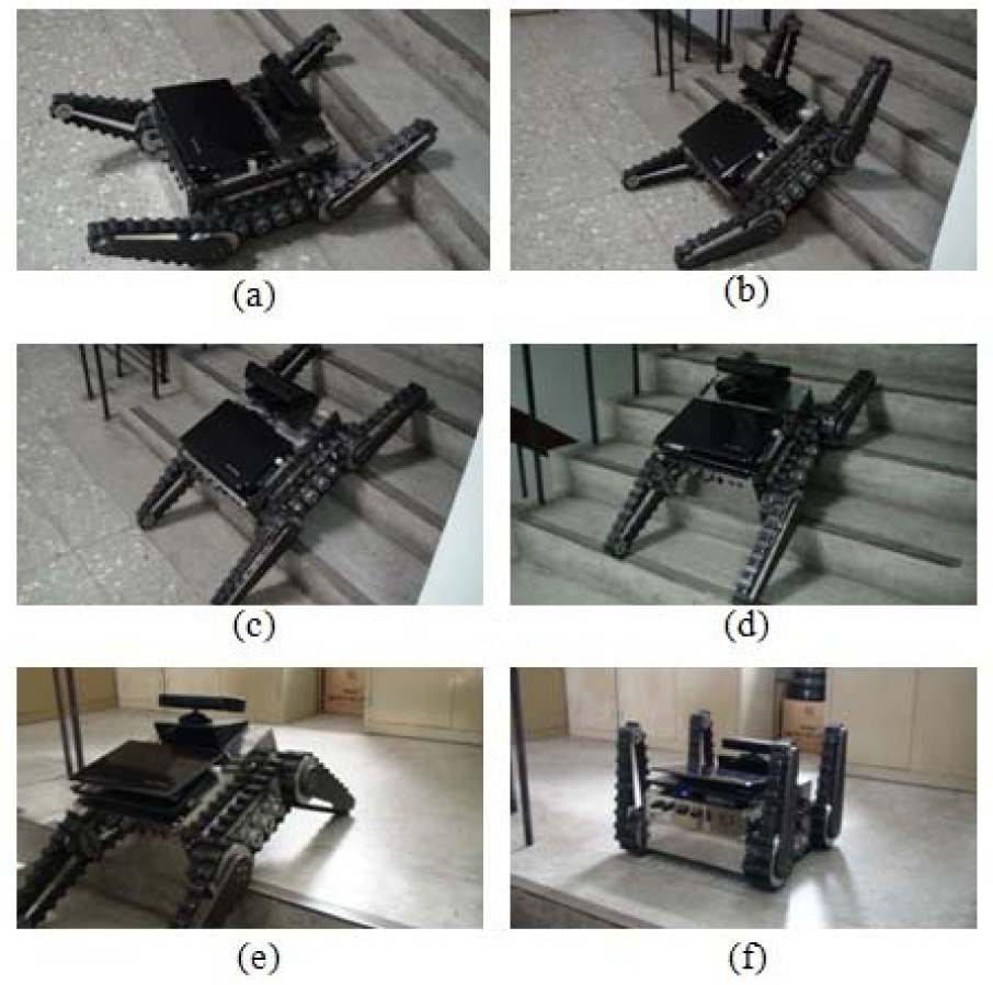
Experimental results of the climbing and landing modes
Figure 30 shows the movement when the tracked robot is on the task of downstairs locomotion. In Figure 30 (a), the tracked robot changes the angle of the Kinect sensor to −250 and starts searching the stairs, and then it moves toward the stairs until the robot's body is overhung the stairs in 100 mm (Figure 30(b)). Subsequently, the robot goes through the climbing mode (Figure 30(c) to Figure 29(e)), the alignment mode, and the landing mode (Figure 30(f) and Figure 30(g)).

Experimental results on the task of downstairs locomotion
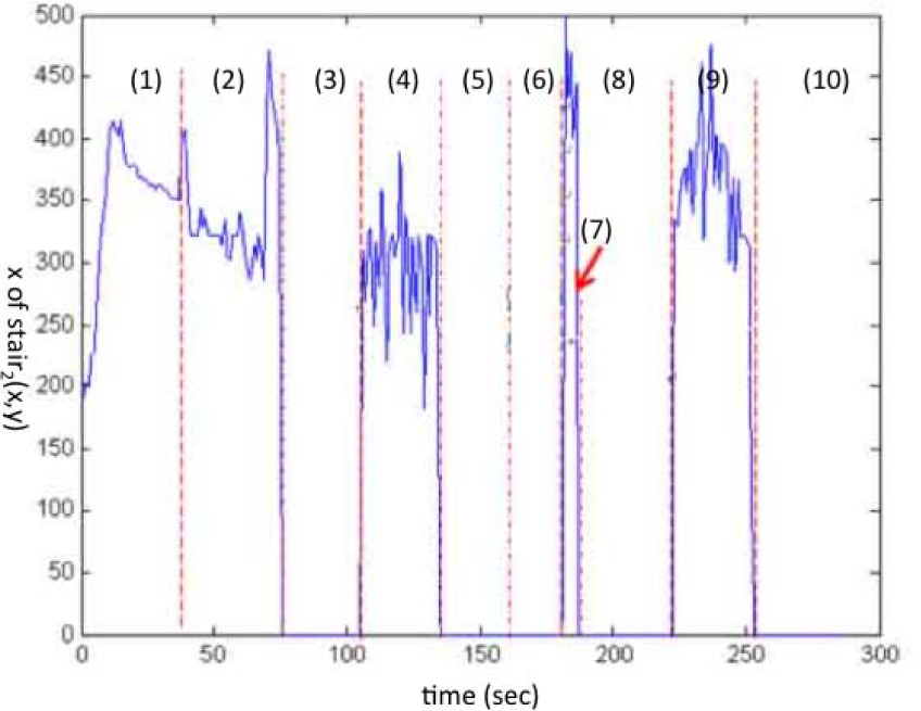
Figure 31 shows the measured distance in ten steps in the experiments. Step (1) shows the variation of the distance d of the pixel stair2(x, y) in the exploration mode. Step (2) shows the variation of the distance of the stair2(x, y) during the alignment mode process. In Step (3), the robot stays in the same location as in Step (2), about 600 mm in the experiment, and changes the track configuration to prepare for the climbing mode. Step (4) shows the variation of the distance of the pixel(320,240). During the 125 seconds to 130 seconds in this step, the robot is approaching the top of the stairs, so the measured depth information is the distance between the robot and the wall behind the stairs; therefore, the measurements become large. There is no record in Step (5) when the robot is preparing for landing. Step (6) shows the robot moving forwards and trying to keep a 700 mm distance from the wall. The robot is exploring the stairs in Step (7) and changing the track configuration to prepare for downstairs locomotion in Step (8). Step (9) shows the measured distance of the pixel(320,240) when the robot is moving downstairs. Step (10) is the landing procedures, where the depth information is out of the distance limitation of the Kinect sensor. Figure 32 shows the coordinate x of pixel stair2(x, y). Step (1) of Figure 32 shows the coordinate x in the exploration mode. Step (2) (upstairs) and Step (7) (downstairs) show the coordinate x in the alignment mode. Step (4) (upstairs) and Step (9) (downstairs) show the coordinate x when the robot is engaged with the tasks of upstairs locomotion and downstairs locomotion. We have no measurement of the coordinate x in Steps (3), (5), (6), (8), and (10), because the coordinate information is not required in the procedures for these steps. Figure 33 and Figure 34 show the speed of the left track and the right track in the different steps.
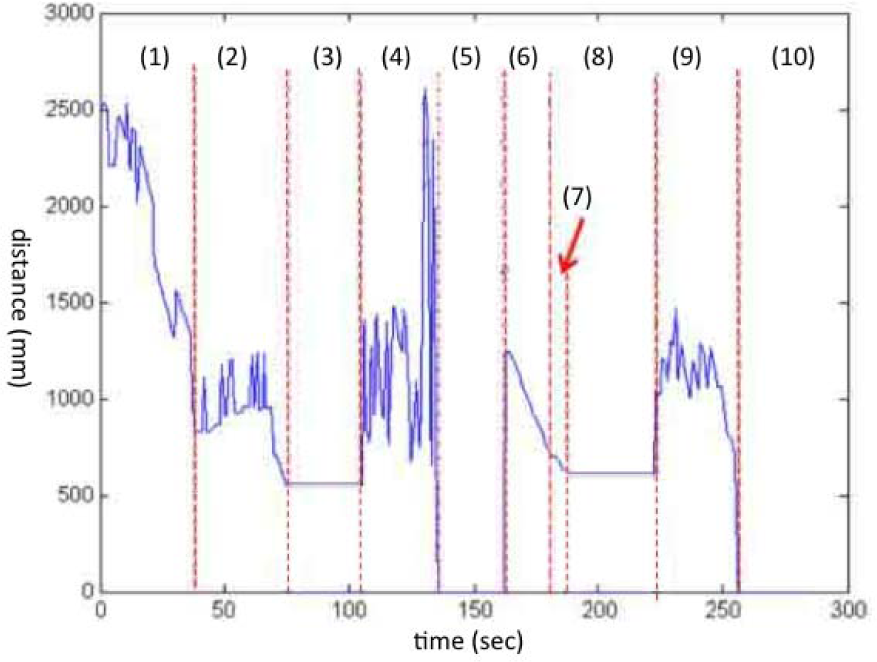
Measured distance of the Kinect sensor
Coordinate x of the pixel stair2(x, y)

Speed of the left track (rpm)

Speed of the right track (rpm)
5. Conclusion
This paper proposed an autonomous mobility controller to perform a stair-climbing task for a tracked robot. Five modes were designed to autonomously explore and climb stairs using only depth information captured by a Kinect sensor. These modes have the advantage of smoothly and safely guiding the tracked robot to complete its tasks. Experimental results showed the tracked robot was capable of climbing up and down stairs, even in an unknown indoor environment.
Footnotes
1
It should be “0” in reality. Here we replace the pixel “0” by an empty cell for a clear illustration in Figures 7 and ![]() .
.
6. Acknowledgements
This work was supported by the National Science Council, Taiwan, under Grants NSC 102-2221-E-234-001 and NSC 102-2221-E-003-009, and the “Aim for the Top University Plan 103J1A12” of the National Taiwan Normal University and the Ministry of Education, Taiwan.