
Abstract
Pole-climbing robots are increasingly needed to carry out high-risk tasks for human beings. A micro pole-climbing robot is designed in this article. A strategy of climbing pole is proposed, which has high precision in each stride. To enable the robot to sample the angle relative to the ground in real time, micro electro mechanical systems (MEMS) three-axis accelerometers are equipped on micro pole-climbing robot. Accelerometer measurements provide an absolute reference for the pitch-and-roll components of the estimated orientation, which are used as feedback input signal of proportional–integral–derivative algorithm. A supporting structure is installed at the joint of each gripper to assist the robot to clamp a pole. The support structure improves the load capacity of the robot. The maximum load of micro pole-climbing robot is 3.5 times its own weight. The climbing pole strategy includes the following sections: a Denavit–Hartenberg model is established and the inverse kinematic solution is analyzed; the flip locomotion is analyzed; and the parameters of KP , KI , and KD in the proportional–integral–derivative control method are obtained according to the Ziegler–Nichols controller. The performance of pole climbing based on micro pole-climbing robot prototype was tested. By using this strategy of climbing pole, the self-continuous climbing with controllable stride is realized, and the angular velocity fluctuation of the five-bar mechanism driven by steering gear is reduced. The average time of a single step is 27 s, the maximum relative error of step distance is 4.6%, and the average relative error is 2.8%. These results confirm that the structure scheme and the strategy of climbing pole are feasible.
Introduction
Aerial work to climb poles, 1 –5 trees, 6,7 or trusses 8 –10 can result in worker injuries 11,12 due to human kinematic and spatial limitations. Pole-climbing robots are therefore increasingly wanted to carry out high-risk tasks for human beings. There are many studies about pole-climbing robots with significant achievements. 1 –5,6 –10,13 –24 Autonomous climbing is a necessity for these robots as the operators may not see the next target to be grasped by the robots all the times.
RoMeLa Robot & Mech Lab designed a serpentine robot called HyDRAS, 1 which comprises a serial chain of actuated universal joints for pole climbing. HyDRAS can wrap its body around the structure in a helical shape and rotates its body along its own central body axis to roll up the structure. Haynes et al. made a type of legged robot—RiSE V3. 2 RiSE V3 is used for dynamical, high-speed climbing of a uniformly convex cylindrical structure. It weighs 5.4 kg and is 70 cm long plus a 28 cm tail appendage. Faizal et al. developed a tree-climbing robot to carry its weight by using two servo motors. 6 The robot can only climb the trees with a diameter not larger than 10 cm. Another climbing robot designed by the Chinese Academy of Forestry can climb trees of multiple diameters. 7 Taking a modular approach, a biped-climbing robot (Climbot) was constructed. 13 Climbot implements autonomous climbing with three basic gaits suitable for different occasions. A pole-climbing robot for transmission line was also built. It adsorbs and locates by an electromagnet module, so it can only climb on metal surfaces. 3 Zahra et al. made an electrical pole-climbing robot, which has a good spatial member transition ability, but its size is relatively large. 4 A robot prototype was developed to construct overhead distribution lines in Quebec hydropower stations. 5
The pole-climbing robot Pobot V2 was based on the innovative principle of rolling self-locking 8 ; it uses no energy to maintain itself at a given altitude. There are also a few prototype robots for truss climbing. 9,10,14 Shady3D built by MIT 10 can move along a three-dimensional (3-D) truss structure. The stability of gripping truss is solved, but the shape of truss section is required. The feasible single-step collision-free climbing motion of BiPCRs in space truss was proposed. 15 The 3-D Climber climbing robot developed by Tavakoli et al. 17 is suitable for climbing pipelines. It has a strong maneuverability but with a large size and a slow movement. The robot is designed to crawl or descend with three wheels—two free wheels and one driving wheel. 18
Some robots can do automatic pole climbing. However, there are few discussions on the accuracy of the robot’s climbing steps. This article describes a micro pole-climbing robot (MPCRobot) and proposed a strategy of climbing pole. By using this strategy of climbing pole, the self-continuous climbing with controllable stride is realized, and the angular velocity fluctuation of the five-bar mechanism driven by steering gear is reduced.
Pole-climbing robot architecture
The 3-D model of MPCRobot is shown in Figure 1. It consists of five bar linkages of a
0, a
1, a
2, a
3, and a
4; four joints of

3-D model of the micro pole-climbing robot. 3-D: three-dimensional.
The coordinated actions of a 1, a 2, and a 3 determine the stride of the robot during the overturning process, and a 0 and a 4 transmit the distance to the two graspers g 1 and g 2 without taking part in the determination of the step size. When a 0 and a 4 rotate to each other parallel, the distance between g 1 and g 2 is exactly equal to the stride determined by a 1, a 2, and a 3 according to the geometric relationship of the parallelogram.
The advantage of this design is that the structure only needs a 0 and a 4 to keep parallel with each other and does not require g 1 and g 2 to keep strictly perpendicular to the climbing pole, which simplifies the design of the grippers and also reduces the clamping force of the grippers.
Modelling and analysis
In Figure 1, a
0 and g
1 and a
4 and g
2 are fixed connections, which are represented by l
1 and l
2, respectively. The fixed angle

D-H coordinate system of MPCRobot. D-H: Denavit–Hartenberg; MPCRobot: micro pole-climbing robot.
D-H parameter model
The Denavit–Hartenberg (D-H) coordinate system of MPCRobot is established, as shown in Figure 2. The coordinate system of j
0 is represented by x
0–z
0. The coordinate systems of j
1, j
2, and j
3 are established in turn, such as x
1–z
1, x
2–z
2, and x
3–z
3. The parameters are presented in Table 1.
Parameters of D-H coordinate system of MPCRobot.

D-H: Denavit–Hartenberg; MPCRobot: micro pole-climbing robot.
Kinematics analysis
The general transformation matrix of the two joint coordinate systems can be described as follows

Set

Let the D-H coordinate system of the end of a
3 be N. When the stride distance D is perpendicular to the ground, it is obvious that

Inverse kinematics solutions
,
, and
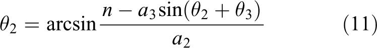
The inverse kinematics of the end effector is solved by using

Assuming


Equation (9) can be obtained by using the universal formula of trigonometric function. Then


In addition, the inverse trigonometric function has only one root in the definition domain
In the inverse kinematic solutions, there are two kinds of solutions which should be abandoned: the wrong mathematical solutions and the infeasible solutions of the system. The wrong mathematical solutions occur because of simultaneous squaring steps on both sides of equation (7). This transformation produces some wrong roots. Such wrong solutions are eliminated by bringing back the original equation. The infeasible solutions are beyond the angle range of the actuator, which can be realized in theory but cannot be realized in actual systems. This kind of solutions is eliminated by defining the rotation angle of the steering gear. The above two kinds of solutions should be removed.
Climbing cycle for locomotion
MPCRobot climbing a pole has two gaits: the flipping-over gait and the inchworm gait. The energy consumed with the inchworm gait is the larger than the flipping-over gait. 13 MPCRobot is used for power line monitoring (with cameras and sensors) and lightning rod detection. This kind of working occasions have enough working space, so this article only discusses the flipping-over gait.
In the process of continuous climbing, the robot’s posture is alternately forward and backward. In this article, the upright posture is defined as the state of g 1 below g 2, otherwise defined as an inverted posture. The self-continuous climbing process with controllable strides is decomposed into two stages: flip and stride.
Flip locomotion
The flip locomotion consists of three steps: loosening gripper g 1, curling up, and turning over, as shown in Figure 3.

MPCRobot flip locomotion. (a) Loosening gripper g 1. (b) Curling up. (c) Turning over. MPCRobot: micro pole-climbing robot.
Firstly, gripper g
1 is loosened, and gripper g
2 is used as the fixed end of the robot, as shown in Figure 3(a). Secondly, the robot’s joints
Stride locomotion
The robot continues to perform stride locomotion after the flip locomotion. In the process of continuous climb, the robot will be alternatively in the upright posture and inverted posture. Whether in the upright or inverted postures, the inverse kinematic solution of stride is invariable. The obtained
After experiencing a row of gesture in Figure 3, the robot is in the inverted posture.

MPCRobot stride locomotion. MPCRobot: micro pole-climbing robot. (a) generating D. (b) paralleling. (c) grabbing with.
First, inputing the expected stride D and using equations (5)
to (11),
Second, by adjusting j
3, the robot keeps the line D between j
0 and j
3 parallel to the climbing pole, as shown in Figure 4(b). When the climbing pole is perpendicular to the ground and the angle between
Finally, the robot adjusts the attitude of the gripper g 1 by rotating j 0 and grabbing the climbing pole with g 1, as shown in Figure 4(c). For climbing robots, it is very important for the gripper to grasp the climbing pole accurately and firmly. Unreliable clamping will cause robot’s falling and serious damages. Traditional calibration schemes use infrared, laser, ultrasound, and other ranging sensors or cameras. 20 –22 By judging the relative position between the gripper and the pole, the robot is guided to realize alignment between gripper and climbing pole. Such schemes require more complex processing and fusion of data from sensors, which increase the cost, size, and weight of robots. This article presents an autonomous gripping scheme based on robot geometry structure, which does not require the use of additional distance measuring sensors. Two supports h 1 and h 2 are added to two grippers g 1 and g 2 to assist the grippers to grasp the pole, as shown in Figure 6(c). With the help of accelerometers mounted on g 1 and g 2, the robot can clamp the vertical climbing pole automatically when two grippers g 1 and g 2 are parallel to each other.
Prototype and experiment
Robot prototype
We designed MPCRobot prototype, as shown in Figure 5. The prototype weighs 1.07 kg (including a battery), and it is 600 mm long when fully extended. The specific size is shown in Table 2. Constrained by the robot’s current structure, a single span of the robot is 8–23 cm. According to the results of the force analysis, the TBS2701 steering gear (its main parameters are listed in Table 3) was selected as the joint motor. This motor has a maximum rotation angle of 270° and can operate in joint mode, in which

MPCRobot prototype. MPCRobot: micro pole-climbing robot.

Installation diagram of acceleration sensors.
Dimensions of MPCRobot components.

MPCRobot: micro pole-climbing robot.
Main parameters of TBS2701 steering engine.
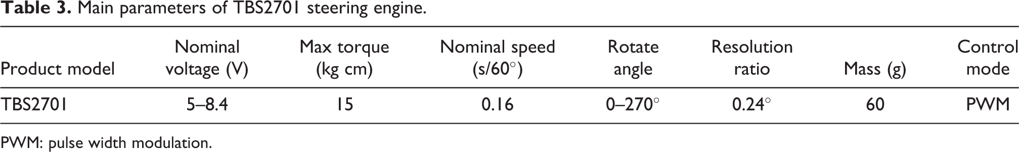
PWM: pulse width modulation.
To enable the robot to sample the angle relative to the ground in real time, micro electro mechanical systems (MEMS) three-axis accelerometers (MPU6050; InvenSense Inc., Sunnyvale, USA) are equipped on
Joint PID control parameters
Overall system with proposed control strategy
Because the steering gear has a dead zone and a hysteresis in control, some control strategies based on proportional–integral–derivative (PID) control theory are developed to reduce the angular velocity fluctuation of a five-bar mechanism driven by the steering gear.
26
Figure 7 shows the overall system with the proposed control strategy, in which the control parameters are the proportional gain KP
, the integral gain KI
, and the derivative gain KD
. 


Overall system with the proposed control strategy.


PID controller parameters
The stabilization time of each adjustment of the steering gear is 1.2 s. The sampling time of the controller is set to

Approximate equal amplitude oscillation under Kc = 4.3.
Main parameters of the steering engine.

PID: proportional–integral–derivative.
PID testing
Experimental conditions are as follows: the angle

Comparison of steady-state error with and without PID algorithm. PID: proportional–integral–derivative.
When
Clamping force of the grippers
Gripper force analysis mode
The grippers need to fix the robot effectively on the pole to avoid sliding. The force analysis model of gripper is derived based on diagram, as shown in Figure 10. The gripper has four main force points of p 1, p 2, p 3, and p 4. p 1 and p 2 are subjected to upward friction forces of FS 1 and FS 2 and outward support forces of FN 1 and FN 2 perpendicular to the rod, respectively. p 3 and p 4 are subjected to upward friction forces of FS 3 and FS 4 and outward support forces of FN 3 and FN 4 perpendicular to the rod, respectively. F31 and F 42 are the friction forces when the gripper rotates clockwise with respect to the pole. F 32 and F 41 are generated when the gripper rotates counterclockwise. F 31 and F 42 prevent the gripper from turning clockwise. F 32 and F 41 prevent the gripper from turning counterclockwise.

Gripper force analysis.
In order to stay on pole, equation (18) can be obtained


where G is the gravity of the robot at the center of mass m and μS is the static coefficient of friction between gripper and pole. The friction forces of FS 1, FS 2, FS 3, and FS 4 increase with the increases of FN 1, FN 2, FN 3, and FN 4 which are related to the clamping force of the gripper. Above is the static analysis of the gripper force, while the dynamic analysis process is more complex.
Physical testing
In physical testing, the clamping forces of the gripper to hold the pole with different materials (wood, iron, polyvinyl chloride (PVC), and PVC with rubber pad) are tested. The gripper is made of aluminum alloy material. The maximum tension angle of gripper is 55 cm. The maximum torque of the motor driving the gripper is 15 kg cm. The experimental process is as follows: the lower gripper of the robot is clamped, the upper gripper is suspended, and the vertical downward pulling force F is applied at p 2. F was measured with a tensiometer (Edinburgh Instrument, HP-500, indexing value 0.1 N). Increasing F until the lower gripper slips from the climbing rod, and record the value of the pulling force (called critical value of F) at this time. The experimental data are shown in Table 5.
Results of anti-slip load capacity test.

In the test, the clamping experiments of pole climbing with the same diameter, but different materials were carried out. The critical force of the gripper on PVC material is 21.1 N. In order to increase the critical force on the PVC pole, a layer of rubber was wrapped around the PVC pole. From Table 5, the addition of rubber layer did increase the critical value from 21.2 N to 52.3 N, which is due to the increase of sliding friction coefficient between the materials. The experimental results show that increasing the friction coefficient between the gripper and the rod can improve F, which means an increased load capacity of the overturning robot.
Pole-climbing experiment
This article designs an experiment to test the climbing speed and the accuracy of step distance, respectively. On a vertical climbing pole, the robot makes repeated strides with a stride of 8–23 cm. The self-continuous climbing process with controllable stride is shown in Figure 11. The flip locomotion, that is, loosening gripper g 1, curling up, and turning over, is shown in Figure 11(a), (b) and (c), respectively. The stride locomotion, that is, the determination of the stride parameter D, the adjustment of the stride posture, and the clamping of the gripper g 1, is shown in Figure 11(e), (f) and (g), respectively.

Continuous climbing steps of MPCRobot. MPCRobot: micro pole-climbing robot. (a) Loosening gripper. (b) Curling up. (c) Turning over. (d) generating D. (e) paralleling. (f) grabbing with.
The time consumed and the errors of stride are recorded, respectively.
Stride experiment
The measurement started with a curl-up (Figure 11(c)) and ended with grabbing the climbing pole with g 1 (Figure 11(f)). In the physical testing, a single stride was 8–23 mm, and the step length was 1 mm. Sixteen groups of experiments were conducted, and each group was repeated 10 times. Statistics of time consumed for single stride are given in Figure 12. “Percentage” in Figure 12 represents the percentage of the total number of experiments that took time in the abscissa range, and “cumulative percentage” represents the percentage of all results that were less than or equal to the total number of experiments that took time in the abscissa range.

Single stride time chart.
In the test, the step length of each group of experiments was different (from 8 mm to 23 mm), which resulted in different execution time for the robot to complete the step action. The proportion of complete action within 40 s was close to 90%, and the average time consumed was about 27 s.
Flip experiment
When each stride is completed, the distance between two grippers is measured with a ruler. Compared with the set distance, the relative error statistics of the single stride can be obtained, as shown in Figure 13. “Percentage” in Figure 1 indicates the percentage of errors in the abscissa range to the total number of experiments, and “cumulative percentage” represents the percentage of all results less than or equal to the total number of current abscissa errors.

Statistics of relative error of single stride.
The range of a single stride is 8–23 cm. The maximum relative error is 4.6%, and the average error is 2.8%. The single span of MPCRobot is 8–23 cm. The absolute error of a single span is 0.22–0.64 cm.
Comparison of climbing robot
A comparison of climbing robot is shown in Table 6. Pole size indicates the cross section of the climbing pole. The pole size that MPCRobot can clamp is the smallest so as to tighten the pole with smaller diameter. The maximum load of Treebot is 2.9 times its own weight, while the maximum load of MPCRobot is 3.5 times its own weight. This is due to the triangular structure consisting of a gripper, a support structure, and a climbing pole (see Figure 1), which can provide stable support for the robot. The single span of MPCRobot is 8–23 cm, and relative error of stride is 2.8%. Then the absolute error of a single span is 0.22–0.64 cm. MPCRobot striding has high accuracy in each step length. Thus, MPCRobot can be used to climb small diameter poles to complete fixed-point monitoring tasks, such as power line monitoring (with cameras and sensors), truss climbing and lightning rod detection, and other working occasions.
Comparison of main parameters of robot.

Conclusions
A 3-D model of MPCRobot was presented. It consists of five-bar linkages, four joints, two supports, and two grippers. A supporting structure was installed at the joint of each gripper to assist the robot to clamp the climbing pole. The support structure improves the load capacity of the robot. The maximum load of MPcrobot is 3.5 times its own weight. To enable the robot to sample the angle relative to the ground in real time, MEMS three-axis accelerometers are equipped on MPCRobot. Accelerometer measurements provide an absolute reference for the pitch and roll components of the estimated orientation, which are used as feedback input signal of PID algorithm.
A strategy of climbing pole is proposed, which has high precision in each stride. The climbing pole strategy includes the following sections: a D-H model is established and the inverse kinematic solution is analyzed; the flip locomotion is analyzed; and the parameters of KP , KI , and KD in the PID control method are obtained according to the Ziegler–Nichols controller.
The MPCRobot prototype was thus developed and tested for pole climbing. By using this strategy of climbing pole, the self-continuous climbing with controllable stride is realized, and the angular velocity fluctuation of the five-bar mechanism driven by steering gear is reduced. The average time of a single step is 27 s, the maximum relative error of step distance is 4.6%, and the average relative error is 2.8%. These results confirm that the structure scheme and the strategy of climbing pole are feasible.
Footnotes
Declaration of conflicting interests
The author(s) declared no potential conflicts of interest with respect to the research, authorship, and/or publication of this article.
Funding
The author(s) received no financial support for the research, authorship, and/or publication of this article.