
Abstract
Pose estimation for mobile robots depends basically on accurate odometry information. Odometry from the wheel's encoder is widely used for simple and inexpensive implementation. As the travel distance increases, odometry suffers from kinematic modeling errors regarding the wheels. Therefore, in order to improve the odometry accuracy, it is necessary that systematic errors be calibrated. The UMBmark test is a practical and useful scheme for calibrating the systematic errors of two-wheeled mobile robots. However, the square path track size used in the test has not been validated. A consideration of the calibration equations, experimental conditions, and modeling errors is essential to improve the calibration accuracy. In this paper, we analyze the effect on calibration performance of the approximation errors of calibration equations and nonsystematic errors under experimental conditions. Then, we propose a test track size for improving the accuracy of odometry calibration. From simulation and experimental results, we show that the proposed test track size significantly improves the calibration accuracy of odometry under a normal range of kinematic modeling errors for robots.
Introduction
Odometry using the wheel's encoder is the most widely used method for determining the fundamental pose of wheeled mobile robots. However, owing to the assumption that wheel revolutions translate to linear displacement along the ground, wheel modeling errors accumulate as the travel distance increases. Therefore, accurate pose estimation from odometry information requires the correction of odometry errors.
Odometry error sources are classified into systematic errors and nonsystematic errors [1–3]. Systematic errors are vehicle specific and do not usually change during navigation. These are mainly caused by the wheel's kinematic modeling errors. The most significant error sources are unequal wheel diameters and incorrect wheelbases.
Usually, mobile robots use rubber or urethane tires. These tires are difficult to manufacture in terms of the nominal wheel size, and they wear out irregularly through navigation. Besides, uncertainty about the effective wheelbase arises because the tires contact with the floor not at a point but over contact areas. Since the systematic errors accumulate constantly with the actual travel distance, the odometry accuracy can be improved by the correction of these errors.
Nonsystematic errors are caused mainly by actual travel environments. The robot will likely experience some wheel slippage due to irregularities in the floor surface and over acceleration.
External sensors can be added for more accurate pose estimation using the absolute position [4–6]. However, because external sensors can develop unexpected problems during navigation, it is essential to correct systematic errors for odometry accuracy when odometry information is used for pose estimation.
A variety of techniques are available to calibrate systematic odometry errors. Abbas [7] proposed a bidirectional circular path test, which is simple to perform and economical in terms of time. Ivanjko [8] introduced an off-line odometry calibration that is based on optimization. Calibration parameters from distinct systematic errors are compensated using an optimization criterion. Bostani [9] suggested a simple method that is based on two experiments. The robot is programmed to move back and forth for estimating the wheel diameter's scaling error Es. To estimate the error parameters from the odometry error model, Doh [10] proposed a procedure called the PC method that is based on the concept of sensor-based navigation through the GVG path. Wang [11] and Chong [12] analyzed odometry error models and derived the variance of the random errors. Roy [13] and Martinelli [14] suggested a method to estimate both the systematic and nonsystematic odometry errors of a mobile robot during navigation in unknown environments. A practical calibration technique for systematic odometry errors of the car-like mobile robots is introduced in [15–16].
The conventional calibration scheme of two-wheeled differential mobile robots is the UMBmark method [1], which uses the end-point errors of the bidirectional square test for correcting the systematic errors. The main advantages of this technique are its usefulness and simplicity regarding odometry calibration. Although the UMBmark method [1] is effective in calibrating systematic errors, there has been no explanation for its validity for a path track size that is 4mx4m. Therefore, we examine the two main factors for the design of the test track and propose an appropriate track size for improving the accuracy of calibration by correcting systematic odometry errors.
In our previous paper [17], we suggested a design guideline for the test track for calibration experiments. However, the previous approach did not consider in detail the effect of the two factors of approximation errors and nonsystematic errors for a wide range of systematic odometry errors.
The first approach is to analyze the influence of the approximation errors used in the trigonometric functions of the calibration equation. This is because the approximation errors affect the calibration accuracy when the systematic errors are large. The second approach is to analyze the nonsystematic errors. In [1], in order to minimize the effect of nonsystematic errors, the center of gravity of bidirectional runs is applied, and the robot moves slowly. However, a considerably small track may affect the calibration accuracy since the nonsystematic errors are larger than the final position errors arising from the systematic errors. Therefore, the test track size must be decided by considering the wheel-modeling errors and experimental floor conditions.
This paper is organized as follows. Section 2 gives an overview of the UMBmark method [1]. The two main factors for calibration performance are investigated. In Section 3, we propose a reasonable design for the track size using numerical simulation for a wide range of kinematic modeling errors. In Section 4, experimental results confirm that the proposed track design significantly improves the odometry accuracy.
Calibration of Systematic Errors
Illustration of the UMBmark method [1]
The UMBmark method [1] is practical and useful for calibrating kinematic wheel modeling errors. It presumes that the two dominant systematic errors are unequal wheel diameters and uncertainty about the effective wheelbase.
Fig. 1 shows the bidirectional square path test. The robot moves over a 4mx4m square path in both the CW (clockwise) and CCW (counter-clockwise) directions four more times. After these runs, the absolute final position errors of the robot are measured. Then, the Type A and Type B errors in each direction are superimposed to estimate the error parameters.
Fig. 1(a) illustrates the effect of the Type A errors in the CW direction. These errors are caused by an incorrect wheelbase and the amount of erroneous rotation in each nominal 90° turn, which is denoted as α. Also, Eb is defined as bactual/bnominal, where b is the wheelbase of the robot. Fig. 1(b) demonstrates the effect of the Type B errors in the CW direction. These errors are caused by unequal wheel diameters and the orientation error of the curved motion, which is denoted as β. Also, Ed is defined as dR/dL, where dR and dL are the actual wheel diameters of the right and left wheels, respectively.

Illustration of the final position error by: (a) Type A errors and (b) Type B errors, in the clockwise direction from [1].
In this UMBmark procedure, there is no detailed explanation for the design of the 4mx4m track size of the nominal square path. Since the size of the test track is important for the calibration performance of odometry errors, it should be carefully determined by the calibration equations, kinematic modeling errors, and experimental conditions.
When the test track is excessively large, a wide test space is necessary. In addition, as the orientation errors α and β from systematic errors increase, the approximation errors become large. Meanwhile, a greatly small test track may result in small final position errors. This fact implies that the test results are affected by nonsystematic errors. An analysis of these errors is presented in the next section.
In the UMBmark method [1], as shown in Fig. 1, the final position errors x4 and y4 of the 4mx4m square path in the CW directions are simply calculated using the approximations for small angles: sinγ=γ and cosγ=1.
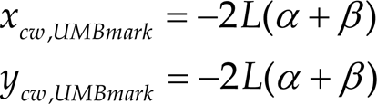

The results of the final position errors of xcw and ycw in the CW direction are obtained by superimposition of the type A and B errors, as in eq. (1). However, the final position errors of xcw and ycw suggest the same value regardless of systematic errors. Compared with the actual final position errors in eq. (2) that are derived from forward kinematics, the approximation errors increase as the orientation errors α and β become large.
The final position errors of the CCW direction have the same result. Therefore, the approximation errors of the calibration equation of [1] are defined as follows.

Within normal systematic errors, as the track size increases, the orientation error β of type B errors become large. It affects the estimation of the Eb and Ed parameters from final position errors of both directions. The analytical results are presented in section 3.
Nonsystematic odometry errors are caused by environmental conditions such as uneven floors or wheel slippage due to excessive acceleration and castor wheels in the experiment. In experiments, the final positional errors are affected by nonsystematic errors as well as systematic errors. Therefore, it is desirable to reduce the effect of nonsystematic errors.
In the UMBmark method [1], to minimize the nonsystematic errors, the robot travels over a smooth floor; further, both the CW and CCW experiments are repeated for a certain number of times. Additionally, the center of gravity of each final-position error cluster is used. However, when the track size is increased, the calibration accuracy is not good because of the effect of large approximation errors.
Eq. (4) shows the estimation of the orientation errors α and β from the final position errors xcw and ycw and the nonsystematic errors εx and εy regarding the calibration equation from [1]. It is clear that if the final position errors are too small, the relative sizes of the nonsystematic errors εx and εy become large.

In order to analyze the effect of nonsystematic errors on the calibration accuracy, we estimate the standard deviation of nonsystematic errors in the experimental test over square paths with the length of one side varying from 1m to 4m. The results of this test are applied in the numerical simulation.
The aim of numerical simulation in this study is an analysis of the effects of approximation errors and nonsystematic errors on the calibration accuracy. In the simulations, according to the track size, the calibration accuracy is evaluated by the difference between the actual and estimated error parameters Eb and Ed under normal kinematic modeling errors.
Fig. 2 shows the approximation errors of the robot's final position after CW and CCW runs over square paths with the length of one side varying from 1m to 4m under the systematic error condition of Eb=0.97 and Ed=0.98. It can be seen that the approximation error is 0.01m for the 1mx1m path. However, as the track size increases, the approximation errors increase exponentially. In the case of the 4mx4m path, the approximation error is about 0.4m in the CW direction. The error parameters are estimated from the approximation errors that are added to the final position errors. This result implies that the calibration accuracy decreases due to approximation errors as the track size increases.

The approximation errors under the UMBmark method [1].
Fig. 3 shows the resultant error parameters Eb and Ed under different track sizes of the square path. The parameter settings are Eb = 0.97 and Ed = 0.98. The actual wheel modeling errors are defined as the parameter settings for the simulator. Since the y axis represents the difference from actual values after calibration, a smaller y value is preferable.

The Eb and Ed kinematic parameter errors after calibration.
From Fig. 3, it is clear that Eb still contains a large parametric error after calibration, while Ed is calibrated accurately. This is because the error source of Eb is the coupled effect of wheelbase errors and unequal wheel diameters. An investigation of the coupled effect was presented in [17].
The resultant parametric errors of the 4mx4m square path in the UMBmark method [1] are as follows: the Eb error is 2.76% and the Ed error is 0.25%. This result implies that the calibration accuracy is diminished by approximation errors, as explained in Section 2.2.
The estimated error parameters regarding the 4mx4m track size are: Eb = 0.9976 and Ed = 0.9825. To validate the accuracy of these parameters, the calibrated robot is driven along the 4mx4m square path track. The larger of the two values for the final position error under the CW and CCW runs,
To evaluate the accuracy of calibration, the calibrated robot obtained from the 1mx1m track size is driven along the same 4mx4m square path track. The resultant Emax,syst is 0.28m. This result shows that the calibration accuracy is improved through a reduction of 0.5m in the final position error as compared with the result for 4mx4m. It is evident that if the track is too large, the calibration accuracy is diminished by approximation errors.
Table 1 shows the estimated standard deviation, obtained through experiments, of nonsystematic errors under four different track sizes. The experimental robot in [18] is driven 30∼40 times over square paths with the length of one side varying from 1m to 4m. The translational velocity of the robot is 0.2m/s. The commercially available STARGAZER system in [19] allows the measurement of the absolute position of the robot to within standard-deviation errors of x=0.17mm, y=0.24mm, and θ=0.37° relative to the static state.
Nonsystematic errors.

From Table 1, it can be seen that the standard deviation of nonsystematic errors increases as the track size increases. To analyze the calibration accuracy, we compare the final position errors under the kinematic modeling error.
Fig. 4 shows the final position errors and the standard deviation of nonsystematic errors after CW and CCW runs over square paths with the length of one side varying from 1m to 4m under the systematic-error condition, Eb=0.97 and Ed=0.98. As the track size increases, the two errors increase.
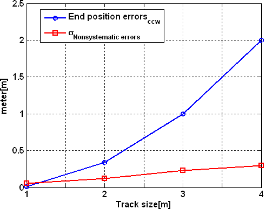
Comparison of the end position errors and the standard deviation of nonsystematic errors.
From Fig. 4, we ascertain that the standard deviation of 0.057m of nonsystematic errors is larger than that of 0.014m for systematic errors for the 1mx1m path. As shown in eq. (4), a large standard deviation of nonsystematic errors decreases the calibration accuracy in actual experiments.
Fig. 5 represents the relative sizes of the standard deviations of nonsystematic and systematic errors under the parameter settings, Eb=0.97 and Ed=0.98, for four different track sizes. It can be seen that the relative size of the standard deviation of nonsystematic errors increases as the track size decreases. In the case of the 1mx1m track size, the proportion corresponding to the standard deviation of nonsystematic errors is 80%. It is clear that if the track is too small, the calibration accuracy is diminished by nonsystematic errors. In order to investigate the multiple effects of the approximation errors and nonsystematic errors upon the calibration accuracy, the following numerical simulations are carried out.
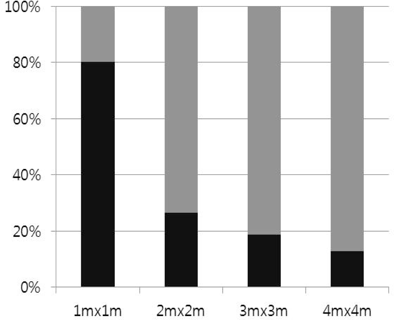
A 100% stacked column chart for the relative sizes of two errors (systematic errors (gray) and standard deviation of nonsystematic errors (black)).
Fig. 6 shows the resultant error parameters Eb and Ed under different track sizes for the square path with and without nonsystematic errors. The parameter settings are Eb=0.97 and Ed=0.98. The nonsystematic errors are applied in the simulations for 500 iterations as in eq. (4) with the standard-deviation values for εx and εy from Table 1. The simulation results represent the mean values over all the experiments. The dotted lines indicate the resultant values of calibration for systematic errors in the absence of nonsystematic errors.

The Eb and Ed kinematic parameter errors after calibration with and without nonsystematic errors.
As shown in Fig. 6, the effect of nonsystematic errors is slight for the 4mx4m track size. However, the calibration accuracy is not good because of the approximation errors. On the other hand, in the case of the 1mx1m track size, although the effect of approximation errors is relatively small, the final position errors are also small. Therefore, because of large nonsystematic errors, the parametric error of Ed is increased from 0.07% to 0.36%. This is because the effect of the nonsystematic errors in the straight path increases as the track size decreases. Thus, the calibration accuracy of the Eb parameter declines.
For the 2mx2m track size, the parametric error Ed is the smallest, viz., 0.16%, among all the other values. Nonetheless, the parametric error Eb is larger than 0.36%, which is the value for the 1mx1m track size. To evaluate the accuracy of calibration in the simulations, the robot calibrated from the four estimation values for Eb and Ed is driven along the same 4mx4m square path track. Then, the resultant Emax,syst is evaluated.
Fig. 7 shows the final position errors for the same 4mx4m square path after calibration using the error parameters estimated through different track sizes. It can be seen that the final position error obtained through calibration is smaller for the 2mx2m track size than for other sizes (this value is 0.46m). Therefore, it can be concluded that in light of approximation errors and nonsystematic errors in experimentation, the calibration accuracy is improved when the 2mx2m track size is employed for odometry calibration.

Comparison of the end-position errors for the same 4mx4m square path over different track sizes.
The error parameters estimated from calibration simulation for the proposed track size and the track size in the UMBmark method [1] are listed in Table 2 for various actual values of Eb and Ed.
Calibration results for various values of Eb and Ed.
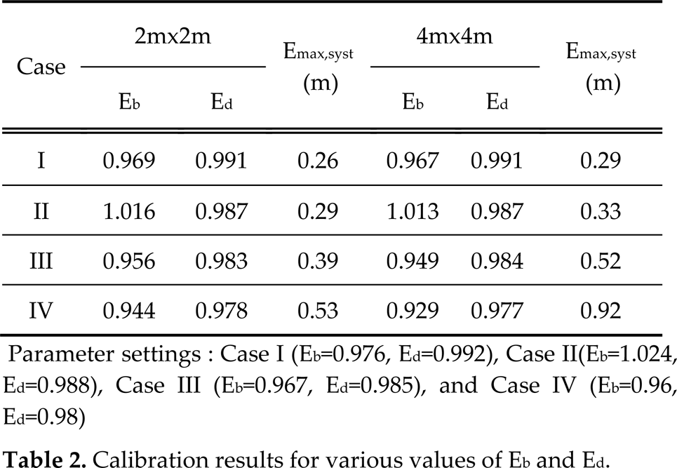
Parameter settings: Case I (Eb=0.976, Ed=0.992), Case II(Eb=1.024, Ed=0.988), Case III (Eb=0.967, Ed=0.985), and Case IV (Eb=0.96, Ed=0.98)
Numerical simulations are carried out for evaluating the calibration accuracy for traversing the same 4mx4m square path track 300 times under the estimated error parameters in Table 2. Here, Emax,syst represents the mean value over all the experiments for various simulation cases. The result shows that the odometry accuracy is improved under normal wheel modeling errors when the proposed track size is applied.
Experimental setup
In this section, we present experimental results that validate the proposed design of the track size for improving the calibration accuracy.
Fig. 8 shows the two-wheeled differential drive robot from [18] used for the experiments in this study. The configurations of the robot were: wheel diameter = 150 mm; wheelbase = 385 mm; encoder resolution = 200,000 pulses/rev; and sampling time of encoder signal = 0.1 sec.

The mobile robot used in the experiments.
The normal range of the wheel modeling error of a robot varies with the wheel properties and environmental conditions. We define that the wheel diameter error relative to the nominal wheel diameter is limited to ±2.5%. The robot used in the experiments satisfied the threshold for the wheel diameter error, namely, ±1.0%.
To evaluate the calibration accuracy of the proposed 2mx2m track size and the 4mx4m size used in the UMBmark method [1], we carried out experiments in odometry calibration.
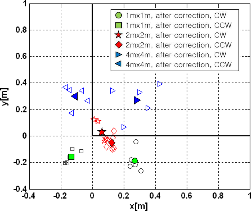
The robot was driven five times at 0.2m/s over each 2mx2m and 4mx4m square path track in both the CW and CCW directions. Using the final position errors measured by the STARGAZER system, the error parameters were calculated. Then, the resultant Emax,syst was evaluated for the same 4mx4m square path after calibration using the estimated error parameters from different track sizes.
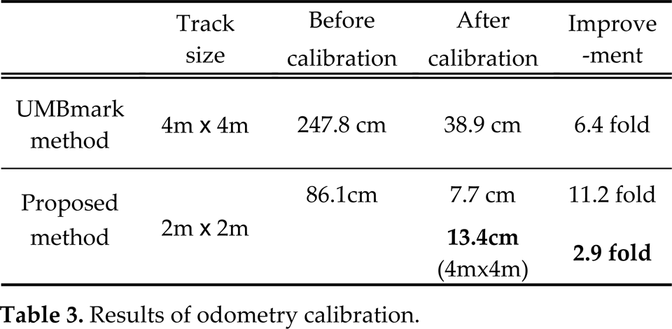
The experimental results are presented in Fig. 9 and Table 3. The final position error before calibration for the 4mx4m track size used in the UMBmark method [1] was 247.8cm. After calibration, the error reduced to 38.9cm. Therefore, the odometry accuracy increased by 6.4 times using [1]. The final position error before calibration under the proposed 2mx2m track size was 86.1cm. After calibration, the error reduced to 7.7cm. As a result, the odometry accuracy increased by 11.2 times using the proposed method.
Results of odometry calibration.
Results of odometry calibration.

Comparison of the two calibration results. The final pose errors decreased after calibration.
Fig. 10 shows the experimental results for validating the proposed track size. The final position error for the same 4mx4m square path after calibration using the proposed 2mx2m track size reduced to 13.4cm.
Comparison for the 4mx4m square path. The final pose errors decreased under the proposed scheme.
The accuracy of calibration was 2.9 times better than that of the UMBmark method [1]. Also, the final position error for the same 4mx4m square path after calibration using the 1mx1m track size was 32.6cm. This is because a considerably small track size is not good for calibration accuracy, as explained in Section 3.
Fig. 11 shows a comparison in terms of the final position error in three cases for the same 4mx4m square path. It can be seen that the odometry accuracy improved significantly by the application of the proposed 2mx2m track size.
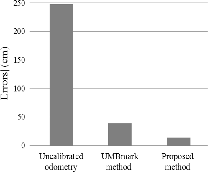
Comparison in terms of the odometry accuracy regarding the end-position errors for the same 4mx4m square path.
The estimated error parameters Eb and Ed from the calibration experiments involving the track sizes under the proposed method and the UMBmark method [1] are listed in Table 4. To evaluate the effectiveness of the odometry calibration under the proposed 2mx2m track size relative to that under the UMBmark method [1], we made the robot travel the 4mx4m square path track in both the CW and CCW directions.
Results for the error parameters for calibration for the two wheel differential mobile robot under various track sizes.

Fig. 12 shows the odometry paths for the same 4mx4m square path in the three cases. The robot was manually driven at 0.2m/s along the reference path four times in both directions. The actual position of the robot remained in the reference path. Although the error between the odometry and reference paths decreased after odometry calibration using [1], it still remained. As shown in Fig 12, it is clear that the final position error from the starting position under the proposed method was much smaller than under other methods. This implies that the systematic errors were calibrated accurately.
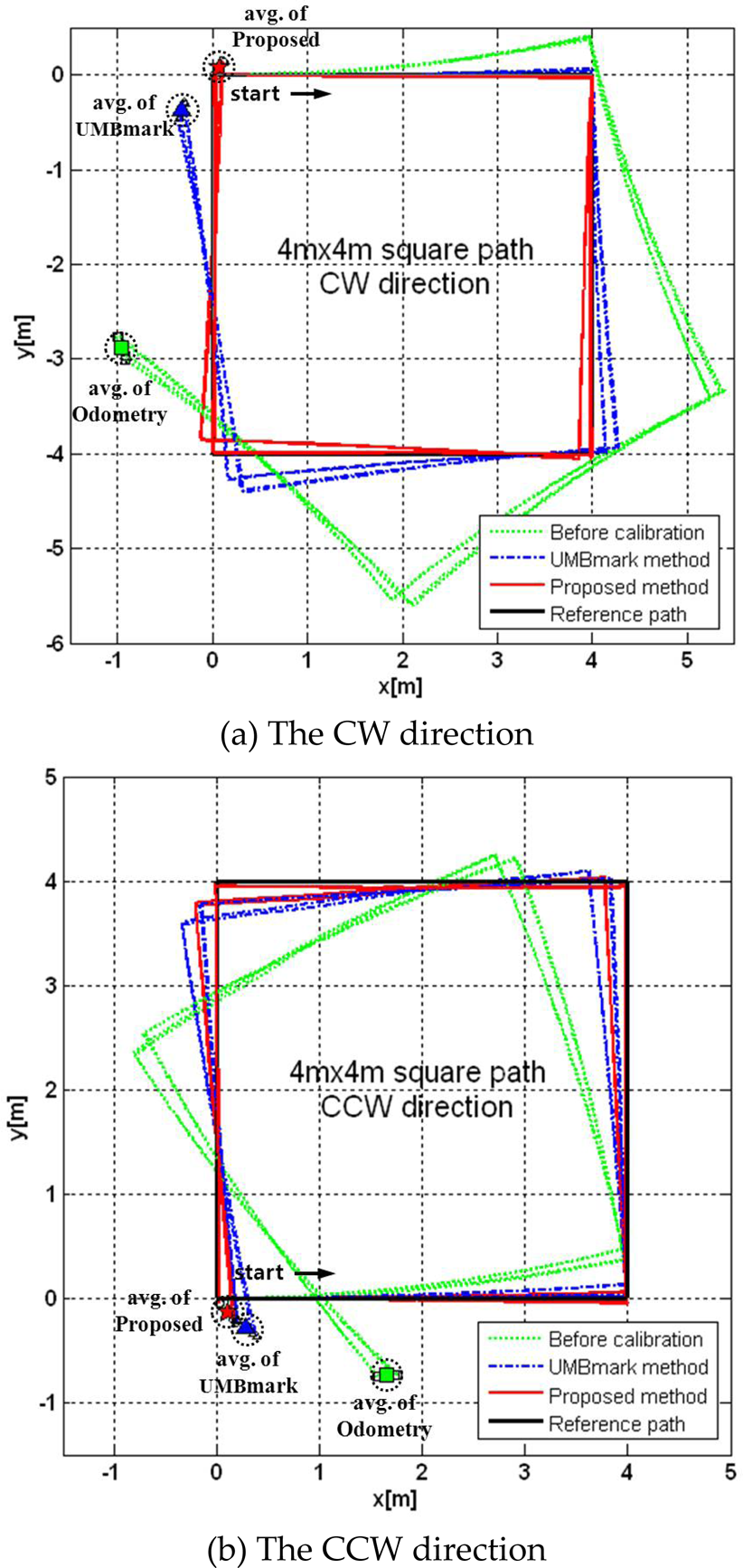
Comparison of the three cases in both directions regarding the odometry accuracy (Before calibration / UMBmark / Proposed).
The experimental results are presented in Table 5. The average positional error before calibration was 2.42m.
Results of the experiments.

The error reduced to 0.45m through the UMBmark method [1]. When the proposed scheme was applied, the error significantly reduced to 0.13m. The final position under the proposed scheme was more accurate by 3.3 times compared to that under the UMBmark method [1].
Fig. 13 shows the odometry errors relative to the reference path for the three cases in both directions. The figure clearly shows that the odometry error relative to the reference path is much smaller under the proposed scheme than under other methods. It can be seen that the odometry accuracy is improved under the proposed track size as the travel distance increases. The experimental results have verified that the proposed track size improves the accuracy of odometry calibration under a normal range of kinematic wheel modeling errors.
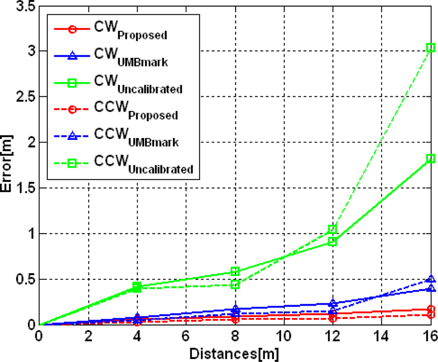
Increase in the average odometry error in the three cases (Without calibration/UMBmark/Proposed).
This paper proposed a design for the test track for the improvement of the calibration accuracy in the UMBmark method [1]. To solve this problem, two principal factors were investigated. First, we analyzed the approximation errors of the calibration equations. Then, we examined the nonsystematic errors under actual experimental conditions. Through an analysis of the relevant factors, we suggested an appropriate track size. The numerical simulations and experiments clearly verified that the proposed scheme provides more accurate calibration results compared to [1]. The proposed scheme is practical and effective for two-wheeled differential mobile robots.
Footnotes
6.
This work was supported in part by Basic Science Research Program through the NRF funded by the MEST (2010-0022609). This work was also supported in part by the MKE under the Human Resources Development Program for Convergence Robot Specialists. This work was also supported by the ITRC support program.