
Abstract
A novel method of indoor mobile robot navigation is presented. The proposed approach fuses the data of odometry and electronic compass for navigation. It includes two calibration methods and a fusion algorithm. First of all, calibration method of systematic odometry error is used to reduce the error of navigation and provide the reliable estimate of pose of mobile robot for adaptive extended Kalman filter fusion algorithm later. Secondly, calibration method of electronic compass using an adaptive neural fuzzy inference system provides direction angle of mobile robot as observation for adaptive extended Kalman filter algorithm later. Finally, a fusion algorithm using adaptive extended Kalman filter algorithm fuses data of odometry and electronic compass that provides the position and orientation of mobile robot. In addition, the value of the parameter k of adaptive extended Kalman filter algorithm which is related to the process noise covariance is decided by fuzzy algorithm. In order to illustrate the feasibility of the proposed approach, two types of experiments are done: the first-type experiment is that the mobile robot runs along default path only with odometry, and the mobile robot with odometry and electronic compass in the second-type experiment utilizes the proposed approach for navigation. The results of experiments show that the error of localization and navigation in the first-type experiment is larger than one in the second-type experiment. They prove the good performance of the proposed approach.
Introduction
Navigation is a basic capability of mobile robotics that has to be solved, 1,2 which has always been an open and challenging problem in the past few decades. 3 In the proliferation of navigation technologies, localization is one of the fundamental problems in mobile robot navigation. In an indoor environment, localization is identified as a problem of estimating the pose, that is, position and orientation of a mobile robot. 4 Location information of mobile robot for movement in a given environment is indispensable. 5 The solutions to the localization problem can be roughly grouped in the following categories: dead-reckoning systems, integrated localization systems, and perception-based localization systems. Dead-reckoning systems are incremental positioning methods which make it possible to estimate the total distance traveled from a starting point. Dead-reckoning systems do not require external sensor information to estimate the position and the orientation. However, dead-reckoning systems have a problem that the estimation error accumulates over time. So these methods require periodical updating to correct the error accumulated in the robot’s position. Dead-reckoning systems can be distinguished two groups: odometry and inertial navigation systems. 2,5
Odometry is widely used to estimate the position and orientation for mobile robot. It is one of the most common relative position estimation methods. 6 –9 In most mobile robots, the offset from a known starting position is computed by data of encoders which are mounted on wheels to monitor the wheel revolutions and/or steering angle of the robot’s wheels. Odometry can be implemented independently without external information outward. Hence, odometry is simple, inexpensive, and easy to accomplish in real time. However, odometry is strongly influenced by internal systematic factors and non-systematic factors which cause the unbounded accumulation of errors. 6,7,10 So a calibration of odometry error for accurate odometry is essential. Odometry error falls into two categories: systematic error and non-systematic error. 11 Systematic error has nothing to do with the external environment; it stays almost constant over prolonged periods of time. 12 In order to reduce systematic odometric errors, different methods have been suggested to model the systematic odometry errors and implemented practically on actual robots for validity. Johann Borenstein and Liqiang Feng 6,7 suggest a bidirectional square path test, called University of Michigan Benchmark (UMBmark), for reducing systematic odometry errors caused by kinematic imperfections of a mobile robot. UMBmark test is a very effective method and correction making the parameters of odometry more accurate and reliable. In the course of over 12 years of experimental work with differential-drive mobile robots, Borenstein et al. 6 observe that the three most notorious systematic error sources are “unequal wheel diameters,” “the uncertainty about the wheelbase,” and “the difference between the average of the two actual wheel diameters and the nominal wheel diameters.” The “unequal wheel diameters” has an effect only straight-line motion, while “the uncertainty about the wheelbase” affects only when turning. However, “the difference between the average of the two actual wheel diameters and the nominal wheel diameters,” the error of which is denoted as scaling error, affects when straight-line motion and pure turning motion. Borenstein et al. hold that the scaling error is exceedingly easy to be measured with just an ordinary tape measure, even though it can be a significant error. So the scaling error is not considered for UMBmark test which only considers the errors caused by unequal wheel diameters and the uncertainty about the wheelbase. However, Weihua Wang et al. 12 think that the scaling error is not easy to be accurately measured for the mobile robot with a low precision of motion control model. So Weihua et al. 12 consider the scaling error for the bidirectional square path experiment. But they only regard the scaling error affecting when pure turning motion and no effect when straight-line motion. In this article, the mobile robot is calibrated by a calibration method proposed by Tie et al.. 13 This calibration method takes into account the effect of those three dominant system errors when turning motion and straight-line motion. And the calibration method utilizes a straight-line path and a turning on the spot experiments which only needs smaller experiment site. The method is simple and easy to handle.
Although methods described above can reduce the odometry error and improve the accuracy of mobile robot navigation, odometry still exists the unbounded accumulation of errors caused by non-systematic error. So researchers are committed to combine odometry with external sensors to eliminate the odomerty errors. External sensors, such as cameras, 14 –19 laser range finder, 15,16 ultrasonic, 20 radio frequency identification devices (RFID), 21 and electronic compass, 16,19 have been used to obtain the required measurements.
The largest factor of odometry error is due to the rotation of the robot, so the error of orientation influences the pose of mobile robot most. 4,22 So electronic compass is a more popular sensor for the orientation of mobile robot. Lee and Jung 23 design global position tracking control of an omni-directional mobile robot (ODMR) using the fusion of odometry and magnetic compass, and the purpose of magnetic compass is to compensate for a direction angle error of odometry errors caused by wheel slip. Jianming Guo et al. 24 suggest a self-localization method of mobile robot combined with RFID, ultrasonic, electronic compass, and speedometer and use extended Kalman filter to reduce the error accumulation during RFID position changing. Zhang et al. 25 propose a self-localization method for the mobile robot in known environment based on the fusion of multisensor information from the all-forward wheel, omni-vision, and electrical compass and use the Monte Carlo (MCL) particle filtration method which combined the measured data of sensors in various observation points to achieve self-localization for the mobile robot. Li et al. 26 design an integrated navigation and control system with high-precision laser radar and electronic compass for a substation intelligent robot based on the Kalman filtering and fuzzy control theory. Ning et al. 27 design an intelligent navigation control system with scanning ultrasonic for the robot sensing its surroundings, and its location system is composed of encoders and compass. Literature described above ignores the magnetic interference for compass. However, electronic compass suffers from local deviation effects due to local magnetic interferences in the indoor environment. There are a lot of sources of magnetic interference such as reinforced concrete structures (floor and walls), pipes, built-in cabling, wiring, and different metal and magnetic objects. The fundamental problem of electronic compass which is used in the indoor mobile robot localization and navigation is a deviation produced by external magnetic interference. Such external magnetic interferences may dramatically increase electronic compass errors which cannot be compensated through calibration. 28 Hence, how to solve the magnetic interference problem should be considered before electronic compass is used in localization and navigation of an indoor mobile robot. Kwon et al. 29 propose a statistical calibration method to obtain optimal parameters dealing with magnetic interference and some necessary conditions for the earth’s magnetic field (EMF) are derived to offer clues to correctness of compass data. Literature 30 has introduced a calibration method for electronic compass based on Fourier neural network trained by modified particle swarm optimization. The advantage of the calibration methods with respect to the studies by Kwon et al. and Kun et al. 29,30 is the error compensation of electronic compass’s azimuth. But it is difficult to get the accurate value of electronic compass on any position of the robot motion path. In order to solve this problem, a calibration method of electronic compass using adaptive neural fuzzy inference system (ANFIS) in this article is proposed as follows.
Because of the shortcoming of using odometry or electronic compass alone, a lot of literatures fuse the data of multisensors employing extended Kalman filter (EKF). Such as, literature 16 presents an EKF approach to localize a mobile robot with two quadrature encoders, a compass sensor, a laser range finder (LRF), and an omni-directional camera. Literature 31 fuses the data of odometry and electronic compass using adaptive extended Kalman filter (AEKF). The AEKF algorithm in the study by Weihua 31 considers the effect of encoder measuring precision for robot localization. And the odometry noise model is established to estimate noise statistical characteristics in real time, adaptively. The AEKF algorithm can ensure mobile robot localization stable and accurate. But the value of the parameter k in the odometry noise model is empirical value which is not adapt to all robots. In this article, we determine the value of the parameter k adopting fuzzy algorithm. So the AKEF algorithm proposed in this article is more robust.
In this article, odometry and electronic compass are used for an indoor mobile robot navigation. In order to improve the accuracy of localization and navigation, an approach including two calibration methods and a fusion algorithm is presented. First of all, a calibration method of systematic odometry errors 13 is used to reduce the odometry error for indoor mobile robot in a short distance and provide the reliable estimate of pose of mobile robot for AEKF later. Secondly, a calibration method of electronic compass using ANFIS is used to solve the magnetic interference problem and provide direction angle as observation for AEKF algorithm later. Finally, AEKF is used to fuse data of odometry and electronic compass. In addition, the value of the parameter k of AEKF algorithm which is related to the process noise covariance is decided by fuzzy algorithm. The fusion of odometry and electronic compass using approach proposed in this article can calibrate the orientation error of mobile robot in real time to improve the accuracy of localization and navigation. The rest of this article is organized as follows. A brief general overview of the system and problem formulation is given in the second section. In the third section, we detail our proposed approach. The experiments are provided in the fourth section before concluding this article in the fifth section.
System and problem formulation
A differential-drive mobile robot is used in our research. As shown in Figure 1(a), an electronic compass is mounted on the mobile robot. Two ultrasonic sensors, respectively, install on both sides of the chassis, which is used to track the actual trajectory of the mobile robot. And a computer (Intel(R) Core (TM) i5-5250U CPU@1.60 GHz) is as upper computer for the mobile robot. This mobile robot has two drive wheels, two passive wheels, and two castors as shown in Figure 1(b). In this section, odometry system and electronic compass are introduced and discussed. Then, the statement of their problem is discussed.

The robot design. (a) The mobile robot with electronic compass. (b) Odometry system.
Odometry system
As shown in Figure 1(b), two drive wheels are connected to DC motors, and two encoders are mounted on both passive wheels, respectively. The main advantage offered by these encoders is their high resolution. When a passive wheel rotates 360°, 2000 pulses will be detected in this mobile robot. By getting the pulses from encoders, the displacements of two passive wheels can be obtained, and then, the position and orientation of mobile robot can be calculated by these displacements.
As shown in Figure 2, the robot pose at ith time step will be denoted by xi = [xi yi θi]T, where xi and yi are the planar coordinates of the robot, and θi is its orientation. When the wheel base (B) is given, the change in orientation δθi and the average of the distances δDi in ith time step can be calculated as follows, respectively

The robot coordinate system and the position of ith landmark.


where δUri and δUli represent the distances covered at ith time step by the right and left wheels, respectively, they are calculated as


where
δNri and δNli—the incremental pulses of the right encoder and the left one, respectively.
n—encoder resolution (in pulses per revolution, here, n = 2000 p/r).
According to Figure 2, the displacement of the robot in ith time step can be determined by

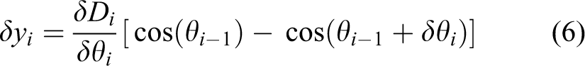
For a small value of δθi, let us assume that
Here,
Electronic compass
An electronic compass is a sensor that obtains its heading (azimuth) by measuring the earth’s magnetic field. The type of electronic compass for our research is DCM230B. Through hard iron calibration, soft iron calibration, and calibration of magnetic interference, the heading accuracy of this electronic compass is ±1°, the azimuth precision is 1°, the allowing range of navigation tilt angle is ±5°, and the antivibration performance is 2500 g. This electronic compass can be used in the operating environment with temperature higher than −20° and lower than 70°.
Problem formulation
As described above, odometry produces the error of unbounded accumulation. A calibration method should be used to reduce the odometry error. In this article, a calibration method proposed by Tie et al. 13 is employed. The method detailed in “Calibration method of systematic odometry error” section is simple and easy to handle. Another problem is that electronic compass mounted on indoor mobile robot suffers from magnetic interferences. We utilize ANFIS to solve this problem. The details are shown in “Calibration method of electronic compass using ANFIS” section. Due to the shortcomings of odometry and electronic compass, respectively, we use AEKF to fuse the data of odometry and electronic compass to improve the precision of localization and navigation. In the AEKF algorithm, the process noise covariance changes with the variation of the position increment of mobile robot in a sampling period, which improves the robustness of the fusion algorithm. The details of fusion algorithm are shown in “Fusion algorithm using AEKF” section. And in “Fuzzy algorithm for the parameter k of the AEKF algorithm” section, the value of parameter k which is related to the process noise covariance is given by fuzzy algorithm.
Proposed approach
The proposed approach includes two calibration methods and a fusion algorithm: a calibration method of systematic odometry error and a calibration method of electronic compass using ANFIS; a fusion algorithm using AEKF. In addition, fuzzy algorithm is used to determine the value of the parameter k which is related to the process noise covariance of AEKF algorithm. The flow chart of this proposed approach is shown in Figure 3.

The flow chart of proposed approach.
Calibration method of systematic odometry error
As described by Borenstein et al., 15 there are three most notorious systematic error sources affecting odometry accuracy: unequal wheel diameters, the uncertainty about the wheelbase, the difference between the average of the two actual wheel diameters and the nominal wheel diameters. In this article, we use a calibration method for these three dominant system errors. The calibration method is divided into two parts: errors influence on the straight-line motion and the turning motion.
Errors influence on the straight-line motion
There are two main notorious systematic error sources which have an effect during straight-line motion. The “unequal wheel diameters” will lead to curved path instead of straight path during straight-line motion. And “the difference between the average of the two actual wheel diameters and the nominal wheel diameters” will lead to the actual distance of robot larger or smaller than the nominal distance. As shown in Figure 4, let us assume that the left wheel is bigger than the right one. The vehicle runs slowly to avoid slippage. Let us denote the nominal distance as L and the actual distance as Lca. Let us further denote the offset of the end point from the straight-line as C and the angle corresponding to its curvilinear displacement as ψ.

Actual path of straight-line motion of mobile robot.
Let us denote the actual curvilinear displacement of the left wheel and the right wheel as

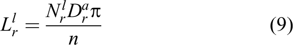
where
n—encoder resolution (in pulses per revolution). As shown in Figure 4, when the actual wheel base (Ba) is given, the actual distance Lca and the angle ψ can be calculated as follows
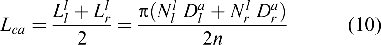

The actual trajectory of mobile robot during straight-line motion which is only affected by “unequal wheel diameters”, and“ the difference between the average of the two actual wheel diameters and the nominal wheel diameters” is seemingly circular arc. As shown in Figure 4, the angle ψ can be calculated as follows according to the geometric relationship
where La is the actual distance between the start point and the end point (the chord length of arc).
The actual distance Lca also can be calculated as follows according to the geometric relationship

where the absolute value of R is the arc radius and the plus or minus of R is the same as ψ.
Errors influence on the turning motion
“The uncertainty about the wheelbase” and “the difference between the average of the two actual wheel diameters and the nominal wheel diameters” are two main notorious systematic error sources when mobile robot turning, which will lead to actual turning angle larger or smaller than the nominal turning angle. As shown in Figure 5, let us assume that the left wheel was bigger than the right one. The vehicle purely turned slowly to avoid slippage. Let us denote the nominal turning angle as τ and the actual turning angle as τa.

Actual path of turning motion of mobile robot.
Let us denote the actual curvilinear displacement of the left wheel and the right wheel as


where
As shown in Figure 5, the actual turning angle τa can be calculated as follows

Solving equation (10) for Lca and substituting in equation (13) yields

Solving equations (11), (16), and (17) as a set of three linear equations with three unknowns

where the angle ψ can be calculated in equation (12).
To sum up, the actual left wheel diameter (
Calibration of the mobile robot used for experiments
The mobile robot used for experiments in this article is shown in Figure 1. This section mainly suggested the calibration of the mobile robot through experiment. Through the calibration, the value of wheelbase and wheel diameters of two passive wheels calculated in equation (18) is more close to the actual value. And the reliable estimate of pose of mobile robot can be achieved which will be used for AEKF fusion algorithm later.
To avoid slippage, the robot is traveling slowly, at a speed of 100 mm/s during the straight-line motion and at a speed of 10°/s during turning motion. An ordinary tape measure with measurement accuracy in millimeters is used to measure distance, and a set square with measurement accuracy in degree is used to measure angle. The encoder resolution (n) is 2000 pulses per revolution. The calibration experiment is defined as the following procedure. At the beginning of the vehicle running, measure the wheelbase (B) and the left wheel diameter (Dl) and the right wheel diameter (Dr) by micrometer. Run the vehicle along a straight-line for L mm at a speed of 100 mm/s and then record the incremental pulses of the left encoder ( Repeat step 2 for h-1 more times (i.e., a total of h runs) and then calculate the average of Make a total of τ turns on the spot at a speed of 10°/s and then record the incremental pulses of the left encoder ( Repeat step 4 for h-1 more times (i.e. a total of h runs) and then calculate the average of Use the average of
At the beginning of running, measure Dl as 40.670 mm, Dr as 40.670 mm, and B as 290.820 mm, and then run the vehicle along a straight-line for 2000 mm and turn 630°on the spot at a time, respectively, which produces the data that
The calibration above is a rough one. Use the results above as the system parameters for the second calibration, such as Dl as 40.068 mm, Dr as 41.800 mm, and B as 291.229 mm for the second calibration, and then run the vehicle along a straight-line for 4000 mm and turn 630°on the spot for 8 times, respectively, which produces the average of data that
Use the results of the second calibration as the system parameters that
From the results of three experiments above, in the third experiment (after the second calibration), La is closer to 4000 mm, C decreases by at least two order of magnitude compared with which in the first experiment (before calibration), and τa is closest to 630°. The end points of the straight-line motion for the three experiments are shown in Figure 6.

The end points of the straight-line motion for the three experiments.
In order to verify the feasibility of this calibration method and acquire system error precision, run the vehicle through bidirectional square path with 3 × 3 m2 square path to express the experimental results quantitatively as the measure of odometry accuracy for systematic errors, Emax,syst.
6
Use the results of the second calibration that
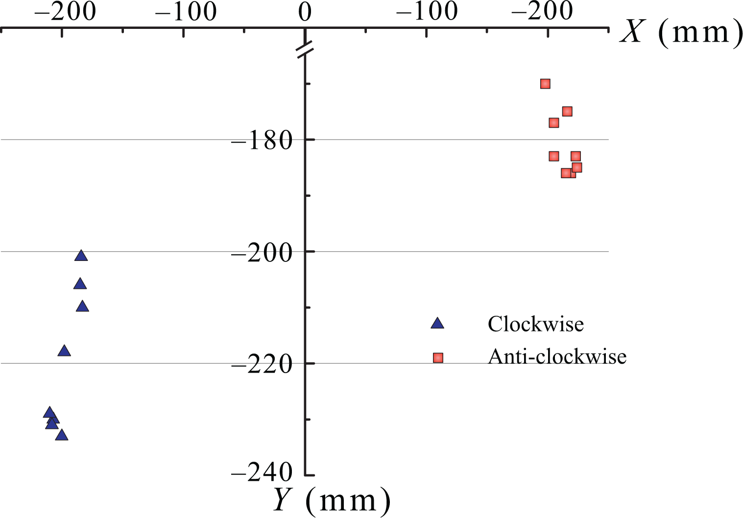
Errors of robot running through bidirectionalsquare path after calibration.
Calibration method of electronic compass using ANFIS
Adaptive neural fuzzy inference system (ANFIS) is one of hybrid intelligent system and the ANFIS used in this article is based on Takagi–Sugeno-type fuzzy inference system (FIS). In ANFIS, back propagation and hybrid are two learning techniques which show the mapping between input and output to compute optimized of fuzzy membership functions. Parameters associated with fuzzy membership functions will modify through the learning process.
To solve the problem of magnetic interferences before navigation of mobile robot, the calibration method of electronic compass is proposed as follows: firstly, sample the output angle of electronic compass and corresponding pose of mobile robot in the default path; secondly, use ANFIS to fit the sampling data that provides the expected angle of electronic compass on any pose in the default path. Through the transformation and calculation, the calibration results can provide the direction angle of mobile robot as observation with smaller error for AEKF algorithm later.
Architecture of ANFIS
As shown in Figure 8, we assume ANFIS under consideration of an input (the x-value or y-value of position of mobile robot as Xc)and an output (the expected angle of electronic compass as f). In order to save computation time, let us denote the x-value of position as input when the variation of x-value is larger than the one of y-value. On the contrary, when the variation of y-value is larger than the one of x-value, let us denote the y-value of position as input. For example, when mobile robot runs along x-direction, the x-value of position will denote as input. On the contrary, when mobile robot runs along y-direction, the y-value of position will denote as input. Particularly, when mobile robot runs along 45° of direction, x-value or y-value can be denoted as input. ANFIS in this article is only applicable to this kind of situation that x-value or y-value is continuous monotone increasing or decreasing. So the movement path of mobile robot must be split into several segments according to x-value or y-value which should be continuous monotone increasing or decreasing in a segment, and then, the inputs and outputs in every segment are fitted by ANFIS.

ANFIS architecture. ANFIS: adaptive neural fuzzy inference system.
In ANFIS, we assume the input variable (Xc) has m language variable values Aj (j = 1,2,…,m), and corresponding m membership functions (MFs) μAj (j = 1,2,…,m). Then if-then rule of a Takagi–Sugeno-type fuzzy inference system is set up as follows.
Rule: if Xc is Aj , then fj = pj 0 + pj 1 Xc
where j = 1,2,3,…, m, and pj 0 and pj 1 are the linear parameters of function fj , and by changing these parameters, we can modify the output of ANFIS structure.
Through the ANFIS system, the expected angle of electronic compass in any position of default path can be obtained. And the error of the expected angle can be controlled by adjusting the parameters of ANFIS.
Architecture of ANFIS for the default paths
There are three default paths for experiments. The first default path is 30,000 mm straight-line on office building corridor. The second default path is a symmetric octagon closed curve on the office building corridor. The third default path is right triangle closed curve on the office building corridor. These three default paths are shown in Figure 9(a) to (c) respectively. In order to developed ANFIS tool box, MATLAB version (R2013a) is used. The input of ANFIS system is the x-value or y-value of position, and the expected angle of electronic compass is considered as the output of the system. Some important parameters such as number of membership functions, types of membership functions (triangular, trapezoidal, bell-shaped, Gaussian, and sigmoid), types of output membership functions (constant or linear), optimization techniques (back propagation or hybrid), and the number of iterations (epochs) in ANFIS tool box are to be adjusted for getting most effective ANFIS model. Model potential is verified using mean squared error (MSE) method.

Three default paths.
The first default path
As shown in Figure 9(a), the first default path is 30,000 mm straight-line on an office building corridor. The starting position of robot is A-point at (0, 0), and the ending position is B-point at (30,000 mm, 0). Sample data points (Xc, f) on this default path with 0.1 s sampling periods by application software. Xc is the x-value of position as input in the ANFIS system, and f is the corresponding angle of electronic compass as output.
The second default path
As shown in Figure 9(b), the second default path is a symmetric octagon closed curve on the office building corridor. The motion sequence of the mobile robot on this path is A-B-C-D-E-F-G-H-A. The positions of this 8 points are, respectively, at A (0, 0), B (4200 mm, 0), C (4200 mm, 4200 mm), D (0, 4200 mm), E (0, 3600 mm), F (3600 mm, 3600 mm), G (3600 mm, 600 mm), and H (0, 600 mm). Sample data points (Xc, f) on this default path which is split into AB, BC, CD, DE, EF, FG, GH, and HA lines. In the ANFIS systems for the AB, CD, EF and GH lines, Xc is the x-value of position as input. On the contrary, Xc is the y-value of position as input for the BC, DE, FG, and HA lines.
The third default path
As shown in Figure 9(c), the third default path is right triangle closed curve on the office building corridor. The motion sequence of the mobile robot on this path is A-B-C-A. The positions of these three points are, respectively, at A (0, 0), B(4200 mm, 0), and C(4200 mm, 4200 mm). The AB line and the BC line are the same as the corresponding lines of the second default path, so the ANFIS systems for the AB line and BC line is the same as those of the second default path. Sample data points (Xc, f) on CA line. Xc is the x-value of position as input.
Use data points as training data to generate fuzzy inference system (FIS) for each line in this three default paths. In FIS for each line, Grid partition method, linear type of output membership functions, and hybrid optimization technique are utilized. In ensuring the MSE is less than 0.5°, adjust the number of membership functions and the number of iterations (epochs) smaller for faster data processing speed and the type of membership functions for smaller MSE. The value of these important parameters is shown in Table 1. The scatters of FIS output labeled as red dots and training data labeled as blue dots are shown in Figure 10. The relationship curves between the inputs and outputs are shown in Figure 11.
Parameters of the first default path.
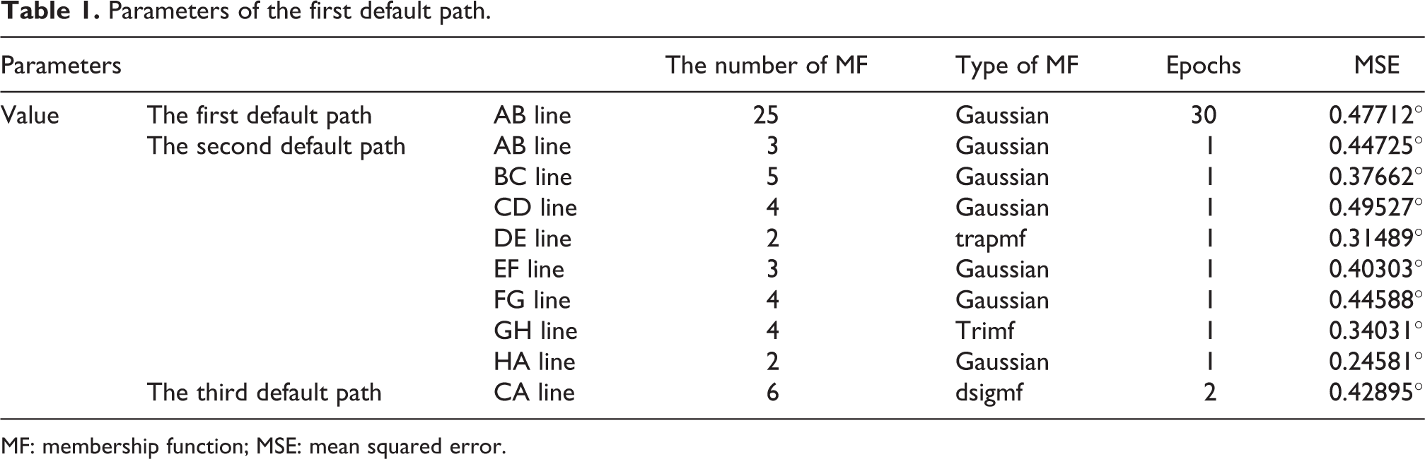
MF: membership function; MSE: mean squared error.

Scatter of FIS output and training data. (a) The first default path. (b) The second default path. (c) The third default path. FIS: fuzzy inference system.

The relationship curve between the inputs and outputs. (a) The first default path. (b) The second default path. (c) The third default path.
Conversion between the angle of electronic compass and the direction angle of mobile robot
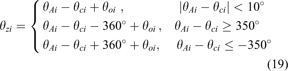
Through the ANFIS systems above, we can obtain the expected angle of electronic compass in any position of default path. Let us assume that counterclockwise direction is positive and the error of direction angle during motion is less than 10°for mobile robot. The range of electronic compass is [0, 360°) which is clockwise from 0°to 360°. At ith time step, let us denoted the x-value or y-value as Xci which is the input for the ANFIS system, the corresponding output (the expected angle of electronic compass) given by ANFIS system as θAi(°), the actual angle of electronic compass as θci(°), and the nominal direction angle which is known for each line as θoi(°). Then, the direction angle of mobile robot (θzi) which is observation for AEKF later can be calculated as follows at ith time step
Fusion algorithm using AEKF
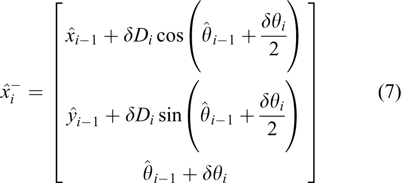
The AEKF fuses the electronic compass measurements with the predicted robot’s position using equation (7) in order to recursively estimate the current position of the robot. The AEKF fusion method can correct the error of direction angle for mobile robot navigation in real time. This will reduce the error of localization of the target position and improve the accuracy of navigation.
In general, Kalman filter addresses the problem of estimating robot position based on two basic models: a process model and a measurement model. The process model describes how the robot’s pose xi changes with time in response to δDi and δθi (which are calculated by equations (1) to (4)) and a noise disturbance wi−1. The measurement model expresses electronic compass observations in terms of robot’s position. θzi is computed by equation (19) which is described in “Calibration method of electronic compass using ANFIS” section. In other words, the process model and the measurement model can be established when δDi, δθi, and θzi are calculated according to the incremental pulses of encoders (δNli and δNri) and the actual angle of electronic compass (θci) which are gotten at the same time by the upper computer. We present the AEKF framework for a discrete-time nonlinear dynamic system as


where the system dynamic models f (·) and h (·) are known. The function h (·) expresses the observed measurement zi. The random variables wi∼ N(0,Q) and vi∼ N(0,R) represent the process and the measurement noise with covariances Q and R, respectively.
The goal of the recursive computation is to estimate the robot’s pose A priori estimate (prediction) Predict the robot’s new position at time step i based on the process model
Compute the error covariance matrix associated with this prediction
A posteriori estimate (correction) Compute the Kalman gain
Update the robot’s position with current measurements zi
Update the error covariance associated with the a posteriori estimate


Fuzzy algorithm for the parameter k of the AEKF algorithm
The values of the parameters
The parameter k has influence on the amplitude and the increase–decrease frequency of the lateral deviation during navigating. As shown in Figure 12, let us denote the amplitude of the lateral deviation as T which is the absolute value of the difference between the maximum lateral deviation and minimum lateral deviation and denote the increase–decrease frequency as F which is the number of cycles of the lateral deviation continuously increase and decrease (the tiny fluctuation of the lateral deviation is ignored due to the measurement error). Adjusting the value of k can control T and F in the allowed range.

The amplitude (T) and the increase–decrease frequency (F).
The first default path shown in Figure 9(a) is chosen for this experiment. Let us assume that the range of the amplitude (T) as [0, 1500] and the increase -decrease frequency (F) as, [0, 10] and the accommodation coefficient (kc) of k is discrete points as {0.5, 1, 10}; then, the value of k in the (i + 1) th experiment (ki + 1) is calculated as follows

where ki is the value of k in the i th experiment and kci is the accommodation coefficient of k in the i th experiment.
In this article, we use a two-input–single-output Sugeno-type fuzzy inference system. The aim of the fuzzy inference system is to decide on kc which belongs to the set {0.5, 1, 10}. The inputs are T and F. The fuzzification membership functions are taken as trapezoidal membership function that illustrated in Figure 13. Four fuzzy rules are defined as follows.

Membership functions. (a) Membership functions of the amplitude (T). (b) Membership functions of the increase–decrease frequency (F).
If T is large, then kc=10
If F is high, then kc=10
If T is medium, and F is low, then kc=0.5
If T is small, and F is low, then kc=1
The rationale behind these rules above is that the accommodation coefficient (kc) of k is decided if T and F are known in every experiment and the value of k in the next experiment will be calculated by equation (28). Through the experiment many times, the value of kc will eventually converge to 1, corresponding the value of k converging to a fixed value. Then, the amplitude and the increase–decrease frequency are all in the allowed range.
Let us assume the value of k in the first experiment is 0.005 (reference the experience value in the study by Kun et al. 30 ). The results of experiments are shown in Table 2, and the trajectory corresponding different k is shown in Figure 14.
The experimental data for deciding the value of k.


The trajectory corresponding different k (0.005, 0.05, 0.5, 5).
Above all, the value of the parameter k is 5 decided by fuzzy algorithm. kl =
Experiments
The mobile robot with differential-drive chassis used in this experiment is shown in Figure 1. There are three default paths of experiment on the corridor of indoor office are shown in Figure 9(a) to (c). Two ultrasonic sensors, respectively, install on both sides of the chassis, which is used to track the actual trajectory of the mobile robot. In order to illustrate the feasibility of the proposed approach, two types of experiments are done to be compared. The first-type experiment uses the mobile robot only with odometry for navigation, and the systematic odometry error is calibrated using the method detailed in “Calibration method of systematic odometry error” section. The second-type experiment uses the mobile robot with the integration of odometry and electronic compass for navigation, and the systematic odometry error also is calibrated using the method detailed in “Calibration method of systematic odometry error” section. In addition, the angle of electronic compass is calibrated using ANFIS detailed in “Calibration method of electronic compass using ANFIS” section; the AEKF is used to fuse the data of odometry and the electronic compass detailed in “Fusion algorithm using AEKF” section; and the value of the parameter k of the AEKF algorithm is 5 decided by fuzzy algorithm detailed in “Fuzzy algorithm for the parameter k of the AEKF algorithm” section.
In two types of experiments, run the vehicle through the three default paths for three times, respectively, at a speed of 200 mm/s during the straight-line motion and at a speed of 10°/s during turning motion. The corresponding trajectories of navigation are shown in Figure 15 for the first-type experiment and in Figure 16 for the second-type experiment. The localization errors of the target positions are shown in Table 3. From Figure 15(a), the mobile robot cannot reach the target pose (30,000 mm, 0 mm) and it will touch the wall because the wide of corridor is 3 m. The end position of the three trajectories are at (16,800 mm, 1188 mm), (16,751 mm, 1186 mm), and (20,201 mm, 1186 mm), respectively. In contrast, the mobile robot which uses proposed approach in the second-type experiment can reach the target pose from Figure 16(a), and the maximum absolute values of the localization errors of the target position in three trajectories are 15 mm for x-direction and 21 mm for y-direction. In the second default path and the third default path, the start position and the target position are all at (0 mm, 0 mm). In contrast to Figures 15(b) and (c) and 16(b) and (c), respectively, the localization errors of the target position in Figure 16(b) and (c) are smaller than which in Figure 15(b) and (c), respectively.

The first-type experiment. (a) Three trajectories in the first default path; (b) three trajectories in the second default path; and (c) three trajectories in the third default path.

The second-type experiment. (a) Three trajectories in the first default path; (b) three trajectories in the second default path; and (c) three trajectories in the third default path.
The localization errors of the target positions.

By comparison with the results of the first-type experiment only with odometry for navigation and the second-type experiment using the proposed approach in this article, the results show that the localization error of the target position in the second-type experiment is smaller than the one in the first-type experiment (at least a 10-fold improvement).
Conclusion
In this article, we have proposed an approach fusing the data of odometry and electronic compass to reduce the error of navigation and localization for mobile robot. The proposed approach includes two calibration methods and a fusion algorithm. First of all, a calibration method of systematic odometry error improves the accuracy of navigation (the Emax,syst is 295.042 mm for 3 × 3 m2 square path) and provides the reliable estimate of position of mobile robot for AEKF fusion algorithm later. Secondly, a calibration method of electronic compass using ANFIS provides direction angle of mobile robot as observation with smaller error (less than 2°) for AEKF algorithm. Finally, a fusion algorithm using AEKF algorithm fuses data of odometry and electronic compass to provide the position and orientation of mobile robot. Through AEKF, the error of direction angle for mobile robot navigation can be corrected in real time. And the AEKF algorithm reduces the error of localization for the target pose and improves the accuracy of navigation. In addition, the value of the parameter k of AEKF algorithm which is related to the process noise covariance is decided by fuzzy algorithm (k = 5 for the mobile robot in this article). So that we can make different mobile robot for different k value which improves the robustness of the system. The results of experiments show that the localization error of the target point in the second-type experiment using the proposed approach in this article is smaller than the one in the first-type experiment only with odometry for navigation (at least a 10-fold improvement). So the approach proposed in this article is viable and can reduce the error of localization and navigation.
Footnotes
Declaration of conflicting interests
The author(s) declared no potential conflict of interest with respect to the research, authorship, and/or publication of this article.
Funding
The author(s) received no financial support for the research, authorship, and/or publication of this article.