
Abstract
Nowadays, multi-sensor fusion is a popular tool for feature recognition and object detection. Integrating various sensors allows us to obtain reliable information about the environment. This article proposes a 3D robot trajectory estimation based on a multimodal fusion of 2D features extracted from color images and 3D features from 3D point clouds. First, a set of images was collected using a monocular camera, and we trained a Faster Region Convolutional Neural Network. Using the Faster Region Convolutional Neural Network, the robot detects 2D features from camera input and 3D features using the point’s normal distribution on the 3D point cloud. Then, by matching 2D image features to a 3D point cloud, the robot estimates its position. To validate our results, we compared the trained neural network with similar convolutional neural networks. Then, we evaluated their response for the mobile robot trajectory estimation.
Introduction
Indoor environments may include slopes to transit from different multilevel areas. Most structured environments provide an even surface useful for robot mapping and exploration, where feature or image extraction is easier than in unstructured environments. Since modern indoor infrastructure includes slopes, mobile robots can navigate multilevel areas.
RGB cameras and light detection and ranging (LIDAR) sensors allow robots to explore structured even-surface scenarios with a robust response. 1 –3
RGB cameras capture scenes in 2D images, and we can classify one image into pixels and superpixels. LIDAR is an active sensor that does not depend on the lighting conditions and provides an accurate distance measurement. However, RGB camera performance depends on illumination, and LIDAR point clouds do not have texture or color information. To overcome those limitations, we can use multimodal sensor fusion. 4 –7
Multimodal fusion uses region levels, 8 and conditional random fields (CRFs) 9 help to model contextual information, but some LIDAR information is lost, resulting in labeling problems. 6,10 Since 3D LIDAR point clouds have plenty of noise, a solution is treating the point cloud as a mesh. 11,12 Point cloud labeling or mesh treatment is viable for large outdoor scenarios. However, for indoor scenarios, the feature extraction has limitations. Mobile robot localization on unstructured scenarios with uneven or multilevel surfaces is still a challenge.
The proposed method aims to provide an efficient solution for image feature detection and mobile robot localization in indoor environments. Nowadays indoor environments are provided with ramps to allow the connection of different levels in indoor environments, such as ramps or access points for wheelchairs. Similar feature extraction methods certainly identify and extract features with a good response. However, our method allows a robust feature extraction and robot localization in indoor environments including multilevel surfaces.
Since 3D point cloud treatment is critical for mobile robot exploration, we propose a multimodal sensor fusion for robot localization on multilevel surfaces employing an RGB camera and a 3D-LIDAR. Using a convolutional neural network (CNN), we extracted 2D features from RGB images and matched them into a 3D point cloud. To perform the 2D feature detection, the input from the RGB camera trains a Faster Region Convolutional Neural Network (Faster R-CNN).
In parallel, the robot extracts features from the 3D point cloud generated from the 3D LIDAR. Finally, we match the features from the 3D point cloud and the camera. Figure 1 shows the pipeline of the proposed concept. The contributions of this document are as follows: a trained neural network for 2D feature detection on multilevel scenarios and a 3D LIDAR–2D camera fusion that enables mobile robot trajectory estimation based on rapid feature detection. Figure 2 shows the proposed strategy to do the neural network training.

Proposed features-fusion model pipeline.

Feature extraction and training strategy using Faster R-CNN. Faster R-CNN: Faster Region Convolutional Neural Network.
Related work
To review the background studies, we divided them into two major areas. The first is CNNs for object and feature detection techniques. The second is the 3D LIDAR point cloud and RGB camera fusion.
ConvNet-based approaches for object detection
ConvNet is an image feature extractor. 13,14 The most popular object detectors are sliding window and region based. Sliding window ConvNet: This is a classic method for object detection. It employs a sliding window mechanism suggested by Sermanet et al. 15 Region-based ConvNets: R-CNN 16 and selective search 10 are methods for object proposal generation. The Faster R-CNN 17 uses spatial pyramid pooling networks. 18 In Faster R-CNN, the image passes through a convolutional layer and finishes with end-to-end training. The fully convolutional network 19 improves object detection and time efficiency. Xiang et al. modify the Faster R-CNN using 3D voxel patterns. 20 Single-shot object detectors: You Only Look Once (YOLO) 21,22 and single-shot detector 23 use a single ConvNet. YOLO divides every input image into a grid, and each grid detects an object within a bounding box. One disadvantage is that the detection accuracy increases during training when YOLO tries to use the entire image, and the detection of small objects could be challenging. Cai et al. 24 implement detection at multiple intermediate networks, dealing with objects of different sizes. Oliveira et al. 25 proposed outdoor localization based on speed invariant inertial transformation and deep learning for the sensor. This localization has applications on terrain classification. With 3D object detection, Yang et al. 26 use convolutional features, and cascade classifiers to reject negative object proposals. Li et al. 27 use deep learning for fusion 2D LIDAR and inertia measurement unit (IMU). They used a recurrent neural network.
3D LIDAR and RGB camera fusion
3D LIDAR is critical for 3D scene perception, as it can capture data both at day and at night. Combining 3D LIDAR with 2D and 2.5D images allows for better 3D scene perception. Shinzato et al. 28 used a graphical method to recognize obstacles. Approaches such as Xiao et al. 6,29 use CRFs. For CNNs, Eitel et al. 30 propose object detection combining color images and depth maps. Schlosser et al. 31 transformed LIDAR point clouds into Horizontal disparity Height above the ground and Angle (HHA) fused with RGB. Asvadi et al. 32 integrated LIDAR and a color camera using deep learning for object detection. Bellone et al. 33 employ a support vector machine (SVM) which identifies roads using 3D LIDAR data. Zhou et al. 34 built an online learning road detector. Quan et al. 35 use the projection of 2D lines into 3D lines. However, the approach depends on geometric computation as initialization to bundle adjustments. Ouyang et al. 36 fuse odometry and wheel encoder to provide localization. Still, the approach is highly dependent on the gyroscope for positioning.
Mobile robots have sensors such as mono and stereo cameras, sonar, 2D, and 3D LIDAR. 37,38 3D LIDAR is an important solution for high-level safety and environment recognition. The wide field of view, distance measurement, and night-vision capability are among the advantages of the 3D LIDAR. The cost of the integrated mechanical parts and the high-power requirements are major limitations for 3D LIDAR. Wisth et al. 39 use multi-sensory odometry for mobile robot localization. The information from visual reference is combined with IMU. He et al. 40 integrate global navigation satellite based on simultaneous localization and mapping pose estimation performing large-scale 3D map building. The authors used global positioning for pose estimation.
Feature detection uses monocular cameras fused with various sensors. For example, to perform road-background detection and classification, the multi-sensor divides an image into pixels and superpixels. Machine learning has important applications such as a mixture of Gaussian, 41 SVM, 4,42,43 and boosting 44 structure random forest. 6 These methods classify each unit independently, but the prediction could be noisy. Xu et al. 45 proposed a multi-sensory fusion using factor graph topology for optimal navigation. 3D LIDAR is crucial for autonomous vehicles too. Markov random fields can model LIDAR information generating a grid map. 46 Yuan et al. 47 proposed a location-based landmark recognition and used a novel quadrupole potential field for obstacle avoidance. Shinzato et al. 5 propose a simple camera–LIDAR fusion for road detection, but LIDAR and cameras have some drawbacks. Sensor fusion is an alternative for a single sensing modality. The extent of work on data fusion 26 techniques in multimodal object detection is classified into three categories: low level, combines the multiple sensor data; middle level, integrated the detected features; high Level, combines classified outputs. 48
For pedestrian detection, Premebida et al. 49 use Velodyne LIDAR with color data. Combining color images and depth maps improves the performance of object detection. González et al. 50 use depth maps and color images as inputs. Schlosser et al. 31 use ConvNet-based fusion for pedestrian detection. Deep learning enhances the HHA data channel from 3D-LIDAR. 51,52 The authors employ color images and 3D-LIDAR point clouds as inputs. These inputs get region-wise features.
Multimodal feature detection
We propose a multimodal feature detection method based on 3D LIDAR and an RGB camera. The RGB images are collected from a Kinect camera and the 3D point clouds from a Quanergy 3D LIDAR. Since the projection of the 3D LIDAR points into the image is sparse, only the 3D point cloud main corners are extracted. The corner extraction process is described in sections “Spatial planar coordinates transformation” and “Division of voting space.” Then, the extracted main corners are fused with the 2D features from the RGB images.
3D point cloud plane extraction
An efficient way to represent a 3D LIDAR point cloud is to segment it into small-scale 3D scenes. Kd-tree accelerates the point cloud segmentation using the normal vector for each point in the 3D point cloud. To proceed with the normal estimation, we use the K-nearest neighbor process to search around the pending points. Then, using the pending and neighbor points, the normal vectors are estimated using principal component analysis. Here,
Spatial planar coordinates transformation
We follow some procedures from Zhang et al. (1) for planar extraction. First, we transformed the spatial planar coordinates to polar coordinates using equation (1)

where

Extracted planes from the 3D point cloud: (a) scanned scenario image, (b) original 3D point cloud, (c) normal vector representation with corresponding angles, and (d) extracted 3D planes.


Division of voting space
For plane fitting with the width (


Feature extraction
Once we completed the 3D planes segmentation, the section “3D Point cloud feature extraction.” describes the procedures for 3D feature extraction from the 3D segmented planes, and the section “2D RGB images feature extraction” describes the 2D feature extraction from RGB images.
3D point cloud feature extraction
Once the 3D point clouds were segmented into planes, we found the intersecting points. The values

3D point cloud plane intersection: (a) original point cloud, (b) intersected points located, and (c) intersected point located in the point cloud.


2D RGB images feature extraction
A trained Faster R-CNN (2) detects the 2D features of RGB images using a region proposal network. Due to our robot employed a Kinect camera for collecting RGB images, the experiment environment has standard lighting conditions of 200–300 Lux. Since the experiment is oriented to indoor environments, we considered a location provided with average indoor lighting conditions. For the particular case of this experiment, the considered lighting conditions (minimum of 200–300 lux) allow the mobile robot to extract features.
To proceed with the neural network training and testing, we started collecting a set of 300 images of the experiment scenario. We used transfer learning for training our neural network. All the images were resized to a 224 × 224 resolution, transformed into gray scale and the Canny edge detector ran on every image. As a result, we obtained a CNN composed of 15 convolutional layers and two fully connected layers. We label 200 images identifying the main corners. The Faster R-CNN ran on the entire image during the training time and testing time. For testing, we used a set of 100 images. Figure 5(a) shows the 2D image capture by the Kinect camera, (b) shows the 2D gray scale of the captured image, and (c) shows the extracted edge using the Faster R-CNN.

Feature extraction from RGB camera images using a Faster R-CNN: (a) original 2D image obtain by the Kinect camera, (b) main edges in the 2D image, and (c) edge extracted using the Faster R-CNN. Faster R-CNN: Faster Region Convolutional Neural Network.
The 2D features were extracted using equations (10) and (11). Here, i is the sequence number of the prior images, j is the index of features in each image,


2D and 3D feature fusion for robot localization
Adapting the procedure in Rublee et al.,
3
we projected the 2D RGB features
Then, a clustering algorithm run on the 2D feature’s coordinates. Equation (12) calculates the candidate’s images

Here, k is the index of the candidates, and the transformation


Here, k is an index of the candidate and

2D and 3D feature projection and rotation: (a) ray tracing projection on the 3D point cloud, (b) RGB camera and 3D point cloud features on the X–Z plane, and (c) RGB camera and 3D point cloud features on the X–Y plane.
Minimization of the robot 3D localization
Once we obtained the 2D and 3D feature fusion, the robot localization is minimized for every position and time


Using the values of

where Pi
is the pose obtained from the previous feature alignment and fi
is the reference robot pose obtained from the IMU. Both fi
and Pi
are
Multi-sensor localization.

Results
To test our experiment, we chose a university location provided with a multilevel surface. The location is divided into three sections, and each section is connected with a 10° ramp, as shown in Figure 7(c). We used a Kobuki robot, 55 a Kinect camera, 56 a Quanergy M8 3D LIDAR manufactured by Quanergy Systems (Sunnyvale, California, USA), 57 and a laptop computer (8 GB RAM and processor intel i7) running MATLAB. Figure 7(a) shows the employed mobile robot and (b) shows the experiment scenario. For the experiment, the linear velocity of the robot was considered without any slip. The robot moved with a linear speed of 0.05 m/s, and the sampling period was 1s. We used a scanning frequency of 0.5 m for LIDAR point cloud registration. Using the mentioned sampling parameters, the robot had enough time for the multi-sensor acquisition.

Scenario and equipment used for the experiment: (a) mobile robot, (b) experiment scenario, and (c) scenario diagram showing three different levels.
For the neural network training, we started collecting all the RGB camera images and trained a Faster R-CNN. Our method employs grayscale segmentation before proceeding with the 2D image feature extraction. The proposed segmentation allows a faster extraction of the major obstacles in front of the mobile robot. Then the robot localizes itself using the features from the trained neural network and the 3D point cloud.
The proposed method was compared with similar transfer learning CNNs as Vgg16 and AlexNet. The response of our method using the Faster R-CNN has a lower training loss compared to the mentioned techniques. The three methods have a high training accuracy and a robust response for object recognition. AlexNet and Vgg16 have trajectory errors of 0.28 m and 0.24 m, respectively. However, our method with the Faster R-CNN reduces the trajectory error to 0.16 m. Table 1 shows a quantitative comparison of the proposed method compared with AlexNet and Vgg16. To optimize the neural network weight updating, we evaluated the training loss. The training loss allows us the interpretation of how well the model is doing for every set. The lower the training loss, the better is the model. Unlike accuracy, training loss is not a percentage, and it is a summation of errors made for each example in training or validation sets. Loss values imply how well the model behaves after each iteration of optimization. Ideally, we expect the reduction of loss after each or several iterations. To obtain the best possible accuracy, we use a Mini Bach size of 128 and a max epoch of 100 for optimal training response. Figure 8(a) shows a quantitate comparison in the training process of the proposed neural network versus similar networks such as VGG16 and AlexNet.
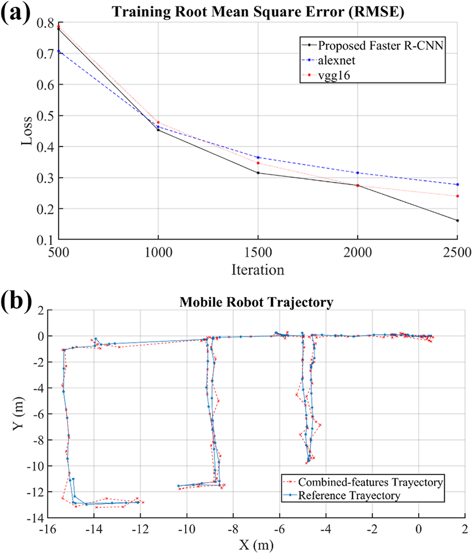
Mobile robot training performance and trajectory: (a) training root mean square error comparison and (b) mobile robot trajectory compared with the reference values.
Proposed faster neural network training comparison.

Faster R-CNN: Faster Region Convolutional Neural Network.
The ground truth for the robot localization was obtained using the odometer and the IMU integrated into the robot. The information collected from these sensors was fused using the extended Kalman filter within a ROS node. Figure 8(b) shows a comparison of the obtained trajectory versus the ground truth trajectory. The axes X and Y represent the coordinates of each robots’ pose measured in meters. As additional validation, we calculated the root mean square error (RMSE) comparing our trajectory versus the ground truth in each level. Table 2 shows the quantitative registration results of the obtained trajectory.
RSME for multi-sensor registration.

RSME: root mean square error.
Discussion
3D mapping and registration face different challenges, such as overlapping areas or sparse features. Our robotic registration framework detects and computes 2D and 3D features using as input two sensors for multimodal localization.
The proposed plane extraction is based on the geometric properties of the 3D point cloud. For the image feature extraction, we trained an artificial neural network using transfer learning. Feature matching into the 3D point cloud is based on the reference described in the section “2D and 3D feature fusion for robot localization.” Lastly, we proposed Algorithm 1 for multi-sensory fusion and mobile robot localization. In the proposed localization, a mobile robot only uses visual reference (color images) and the surrounding environment (3D point clouds). Although we obtained a robust 3D localization during a dynamic scan, we identified two weaknesses. First, if the robot’s velocity is higher than the established linear velocity of 0.05 m/s, the robot may not have enough time to process the data from all sensor inputs. Second, the robot cannot crossover a ramp bigger than 10° due to the wheel diameter. The proposed localization approach can impact on the service industry, improving the monitoring and control of mobile robots in multilevel areas. As future work, the experiment will be performed in outdoor scenarios, extending the neural network training for detecting and extracting more scenario features.
Conclusions
We presented a 2D and 3D feature fusion for mobile robot localization in a multilevel area. The 3D point cloud feature extraction based on plane segmentation reduces the point cloud processing time. The Faster R-CNN identifies the main corners in 2D images. The mobile robot extracts 3D features using 3D point cloud processing. As presented in the Introduction, plenty of methods still rely on positioning sensors as IMU or global positioning system (GPS), which offer a good solution in outdoor scenarios. On the other hand for indoor scenarios, the response of these sensors is limited. The proposed method presents an RMSE around the axis X in 0.053 m and around the axis Y in 0.02 m. Those values are acceptable for mobile robot indoor exploration, meaning that our method has a reliable response in localization, providing an alternative to sensors as IMU or GPS. In terms of neural network efficiency, the proposed method reduced the training loss significantly compared to Vgg16 in 55.18%, and Alexnet in 69.05% keeping the lowest robot trajectory error.
Footnotes
Declaration of conflicting interests
The author(s) declared no potential conflicts of interest with respect to the research, authorship, and/or publication of this article.
Funding
The author(s) disclosed receipt of the following financial support for the research, authorship, and/or publication of this article: This research was supported by Ministry of Trade, Industry and Energy under Robot Industrial Core Technology Development Project program (20015052 and K_G012000921401) supervised by the KEIT.