
Abstract
Odometry using incremental wheel encoder sensors provides the relative position of mobile robots. This relative position is fundamental information for pose estimation by various sensors for EKF Localization, Monte Carlo Localization etc. Odometry is also used as unique information for localization of environmental conditions when absolute measurement systems are not available. However, odometry suffers from the accumulation of kinematic modeling errors of the wheel as the robot's travel distance increases. Therefore, systematic odometry errors need to be calibrated. Principal systematic error sources are unequal wheel diameters and uncertainty of the effective wheelbase. The UMBmark method is a practical and useful calibration scheme for systematic odometry errors of two-wheel differential mobile robots. However, the approximation errors of the calibration equations and the coupled effect between the two systematic error sources affect the performance of the kinematic parameter estimation. In this paper, we proposed a new calibration scheme whose calibration equations have less approximation errors. This new scheme uses the orientation errors of the robot's final pose in the test track. This scheme also considers the coupled effect between wheel diameter error and wheelbase error. Numerical simulations and experimental results verified that the proposed scheme accurately estimated the kinematic error parameters and improved the accuracy of odometry calibration significantly.
Introduction
In autonomous navigation, the position of a mobile robot needs to be estimated accurately. In general, the localization of a robot is based on the measurement of the traveled distance recorded by the wheel's incremental encoders. Odometry information using the encoder is the most widely used navigation method for mobile robot positioning. However, odometry has a well-known drawback: its errors accumulate over time as the robot moves. In order to reduce the odometry errors with increase of travel distance, the odometry errors need to be corrected.
Odometry error sources are classified into systematic errors and non-systematic errors [13]. Systematic error sources include unequal wheel diameters, uncertainty of the effective wheelbase, misalignment of wheels, etc. These are vehicle specific and do not usually change during navigation. Therefore, it is essential to reduce these errors by calibrating systematic kinematic parameters. The calibration scheme of kinematic parameters is the major focus of this paper.
Non-systematic error sources result from environmental conditions, which are probabilistic. Examples are uneven floors, unexpected objects on the floor, wheel slippages etc., which are significant problems in the practical application of robots. The uncertainty of these errors can be modeled by using the absolute position of the robot obtained from external sensors [46].
Calibration of systematic odometry errors have been discussed in many studies. Kelly [7] suggested a general solution for linearized systematic error propagation for an optional trajectory. Antonelli [8] proposed least-square estimations to approximate odometric parameters. Abbas [9] introduced a bi-directional circular path test, in which the robot is driven along a circular reference path in both directions. Ivanjko [10] proposed off-line odometry calibration based on optimization used to compensate calibration parameters from distinct systematic errors. Bostani [11] suggested a simple method based on two experiments, in which the robot is programmed to move back and forth in a straight line to estimate the kinematic parameters and the wheel diameter's scaling error Es.
Doh [12] proposed an odometry calibration procedure called the PC-method that is based on the concept of sensor-based navigation through the GVG path. Roy and Thrun [13] suggested a statistical technique which uses the robot's sensors to automatically calibrate odometry errors as a robot operates. Martinelli [14] proposed an algorithm for an on-line estimation of the odometry errors during navigation in unknown environments. They adopted an Augmented Kalman Filter (AKF) that estimates both the robot's pose and the kinematic parameters to characterize the odometry errors. For the calibration scheme of a car-like mobile robot, the test track design and the calibration equations are presented in [15–16].
The UMBmark method [1] is the conventional calibration scheme of two-wheel differential mobile robots. The wheel diameter error and wheelbase error can be calibrated by driving the robot along a bi-directional square path, and by using the start and final position errors. This approach identifies the odometric kinematic parameters – wheel diameter error and wheelbase error. Although [1] is a practical calibration method for measuring and reducing the odometry errors that are caused by the two systematic error sources, it is ineffective for large magnitudes of systematic errors due to the approximation errors from the calibration equations. The calibration accuracy decreases as kinematic modeling errors become large. In addition, the assumption that the average actual wheel diameter is equal to the nominal wheel diameter does not corresponded with the actual wheel.
In this paper, we propose a new calibration strategy by extending the conventional UMBmark. Our first objective is to propose a new calibration scheme, in which the final orientation errors of a robot on a test track are used for calibration accuracy. The proposed scheme remarkably reduced the approximation errors.
The second objective is to derive new accurate calibration equations from the limitation of [1]. In [17], we proposed approaches for the accurate calibration of kinematic parameters. The calibration equations of [17] were derived by investigating the coupled effect between the wheel diameter error and the wheelbase error for a robot turning 90° on a test track. Based on the research reported in [17], the coupled effect for a straight path in a test track is also considered. The presented numerical simulations showed that the reduction of the approximation errors in the calibration equations and the consideration of the coupled effects between the two error sources were essential for improving calibration accuracy.
This paper is organized as follows. In Section 2, an overview of the UMBmark method [1] is presented and the proposed calibration equations are derived. Section 3 explains the advantages of the proposed calibration scheme by numerical simulations. In Section 4, experimental results are given for the evaluation of the proposed method and for the comparison of the proposed method with other previous calibration schemes. Finally, conclusion is provided in Section 5.
Accurate Calibration of Kinematic Parameters
Illustrations of the UMBmark method [1], Bostani's method [11] and Lee's method [17]
Fig. 1 shows the UMBmark method [1] procedure for correcting systematic odometry errors in bi-directional square path experiments. The robot moves over a 4mx4m pre-programmed square path in both clockwise (CW) and counter-clockwise (CCW) directions to overcome the concealed dual-error problem from an uni-direction path. After the runs, the absolute final position errors of the robot are measured. Then, the kinematic error parameters, namely the wheel diameter error and wheelbase error, are calculated from the calibration equations.

Illustration of final position errors by (a) Type A errors and (b) Type B errors in CW, CCW directions from [1].
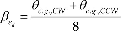
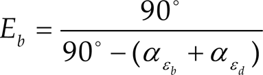
Fig. 1 (a) illustrates the Type A errors due to an incorrect wheelbase and the amount of orientation error α during rotation at each nominal 90° turn. The error parameter Eb is defined as b actual / b nominal , where b is the wheelbase of the robot. Fig. 1 (b) shows the Type B errors due to unequal wheel diameters and the orientation errors (3 during straight motion. The parameter Ed is defined as dR / dL, the ratio between the actual right and left wheel diameters.
In [1], as shown in Fig. 1, the final positions x4, y4 from Type A and B errors in the square path test for the CCW directions are simply calculated using the approximations for small angles: Lsinγ ≍ Lγ, Lcosγ ≍ L. (L: track size, γ:small angle)
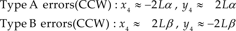
The actual final position of the robot xccw, yccw are obtained by superposition of the Type A and B errors.

The orientation errors α and β are estimated from the final position errors x and y for CW and CCW motions as follows.

In [1], the kinematic error parameters Eb and Ed are calculated from the orientation errors α and β using the final position of the test experiments in CW, CCW directions by eqs. (1)(3). However, odometry calibration accuracy can be reduced by the approximation errors when the kinematic modeling errors become large. Therefore, it is unsuitable for large magnitudes of systematic odometry errors. Furthermore, the calibration equation of [1] is based on the assumption that the effects of wheel diameter error and wheelbase error are totally independent in test motion. This is not true because of the coupled effect between the two error sources in practical application.
In Lee's method [17], the reference track is a 2mx2m square path for the experimental conditions. The robot is driven 5 times in CW and CCW directions, respectively. The final position errors are measured and applied for the calibration of systematic odometry errors. The calibration equations are derived with consideration of the coupled effect of wheel diameter error and wheelbase error at each 90° turning motion on the test track. In [17], however, the calibration scheme include the approximation errors and the coupled effect for a straight motion was not considered.
Fig. 2 shows the Bostani's method [11], which has no approximations in its calibration procedure. In [11], the robot is commanded to move back and forth along a straight path. The robot rotates on the spot by 180° in the CW direction for the first test and in the CCW direction for the second test. The orientation errors γ1 and γ2 were calculated and used for odometry calibration. The test was repeated 5 times to reduce non-systematic errors. In [11], however, the coupled effect between wheel diameter and wheelbase error in rotation motion was not considered in the calibration experiment. Table 1 summarizes the limitations of previous calibration schemes.
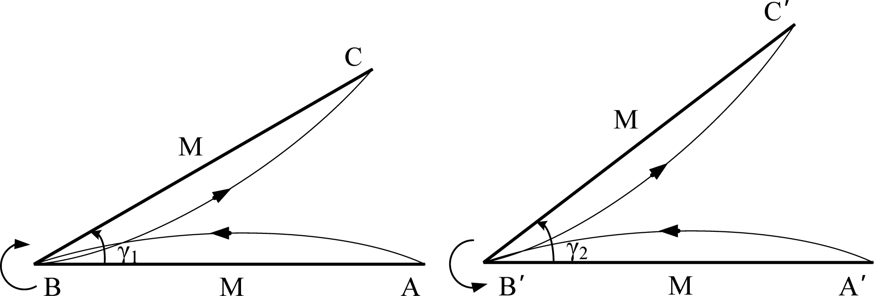
Traveling paths for two experiments of the Bostani's method [11].
Comparison of the odometry calibration schemes.

The proposed calibration scheme considers the orientation errors of the final robot pose on a square path test track to reduce the approximation errors. The calibration equations are derived with no approximations, unlike those of the UMBmark method [1]. It is useful and practical because it only needs to measure the robot's initial and final heading errors in an open loop motion test. In addition, by considering the coupled effects between wheel diameter and wheelbase error in straight motion and 90° turning motion, the proposed calibration scheme can estimate the kinematic error parameter more accurately.
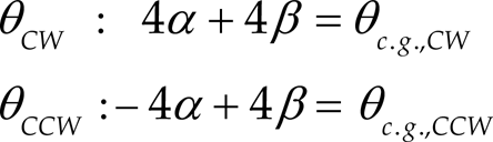
Fig. 3 shows the final robot poses in CW, CCW experiments with Type A and B errors, respectively. The orientation errors of the final robot pose are simply calculated by using α, β from the two errors as follows.
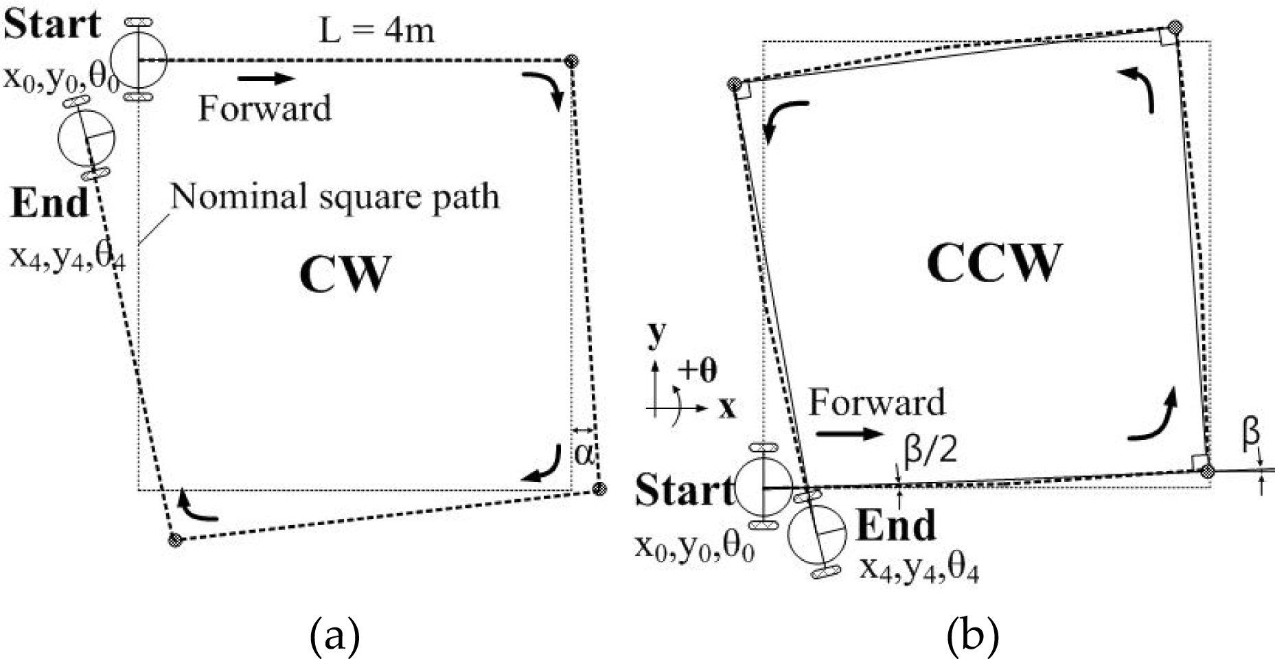
Illustration of the final robot pose errors by (a) Type A errors (CW) and (b) Type B errors (CCW) from [1].

The resultant orientation errors θcw, θccw of the final pose in CW, CCW experiments are obtained by superposition of Type A and B errors as follows.
From eq. (5), 
The orientation errors
(a) Heading error (3 after translation (b) Heading error α after 90° turn
In a practical application, Type A and B errors will occur together. Fig. 4 shows that the orientation errors due to the coupled effects of the two errors after a straight motion and a 90° turning motion in the CCW experiment. The resultant robot orientation errors are newly defined as follows.

Heading errors after motions caused by Type A, B errors in test track.

From Fig. 4 (b), it can be seen that the orientation error 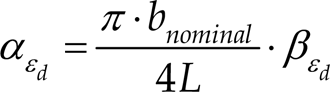
Finally, the expression for the Eb error parameter can be derived as follows. The orientation error α of 90” turning motion in [1] is newly defined, and it is used for computing the wheelbase error Eb.
The robot travels slightly in a curved trajectory of turning radius R in a straight path as shown in Fig. 4 (a). The orientation error 
The numerical simulation is carried out to verify the proposed calibration scheme. The first objective is to show the advantages of the presented calibration scheme, using the robot's final orientation errors and the coupled effects of Type A and B errors of the test track as in eqs. (10)–(11). The second objective is to evaluate the calibration accuracy of the proposed calibration scheme for various systematic error cases.
In numerical simulation, we concentrate on the effect of the systematic errors; therefore, the non-systematic errors were not included. The calibration accuracy is evaluated as the difference between the actual and estimated kinematic error parameters Eb and Ed for different test track sizes. Since the y-axis represents the estimated kinematic parameter's errors compared to their actual values after calibration, a smaller y is desirable. The actual kinematic modeling errors of the wheels are defined to set the values of the parameters used in the simulation.
Initially, Eb = 0.976 and Ed = 0.992. Fig. 5 shows the estimated kinematic parameter's errors by [1]. The parametric errors increase as the track size increases due to the approximation errors. In [1], a 4mx4m track was adopted for systematic odometry calibration. The Eb and Ed still contain parametric errors after calibration, Eb = 0.725% and Ed = 0.030%. For this reason, the effect of the calibration performance with respect to the approximation errors of the calibration equations and the coupled effects of two error sources are explained in section 2.1.
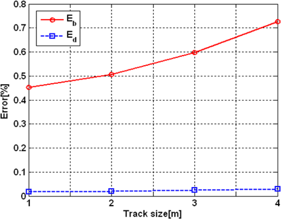
Eb and Ed parameter errors after calibration by UMBmark method [1].
To validate the accuracy of the resultant kinematic parameters, the calibrated robot was driven along the 4mx4m square path track. The larger value of the final position errors in CW, CCW directions, Emax,syst max(rc.g., CW;rc.g., CCW), as obtained from the simulation results, is 0.164m.
Fig. 6 shows the resultant kinematic parameter errors for different calibration schemes under the same Eb=0.976, Ed=0.992 condition. In Fig. 6, the dashed dot line indicates the kinematic parameter errors of [1], and the dashed line represents the errors obtained using the robot's final orientation errors. The kinematic parameter errors are significantly reduced to Eb = 0.392% and Ed = 0.016%. The solid line shows the errors with additional consideration of the coupled effects between the two error sources as explained in section 2.2 (proposed method).

With the consideration of the coupled effects between the wheel diameter error and the wheelbase error in the test track, the odometry calibration accuracy improved. The parametric errors by the proposed scheme reduced to Eb = 0.001% and Ed = 0.003%. The Emax,syst was within 0.01m. This result shows that the Eb and Ed parameters were accurately calibrated by the proposed scheme.
When Lee's method [17], which considered the coupled effect of wheel diameter error and wheelbase error in 90° turning motion on a 2mx2m test track, was applied, t he resultant Eb was decreased from 0.725% (UMBmark) to 0.133% (Lee's). However, the parametric errors still remained due to the approximation errors from calibration equations. These results show that the proposed scheme corrected the parametric errors more accurately.
Table 2 shows the resultant parametric errors of Eb and Ed after odometry calibration with different kinematic error parameters. Numerical simulations evaluated the calibration accuracy of the proposed calibration scheme for Eb larger than 1.0 (case I) and relatively large kinematic modeling errors (case II).
Calibration results for various error parameters cases.
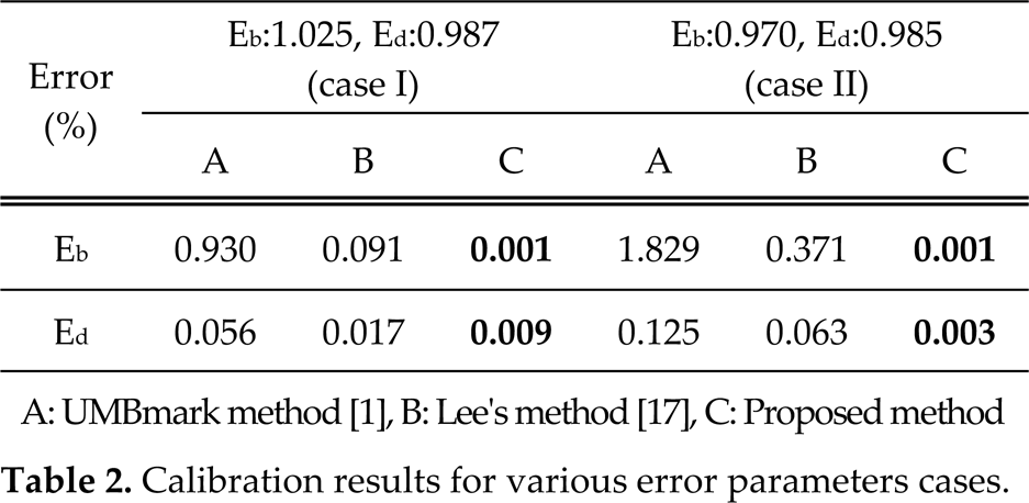
For case I, the resultant parametric errors using the UMBmark method [1] were Eb = 0.930%, Ed = 0.056%. By Lee's method [17], the errors were reduced to Eb= 0.091%, Ed= 0.017%. Therefore, the odometry calibration accuracy was improved when the coupled effects of the two errors were considered in the 90° turning motion for a 2mx2m track. The resultant parametric errors from the proposed method were significantly decreased to Eb = 0.001%, Ed = 0.009%. The proposed scheme of odometry calibration was more accurate than those of [1] and [17]. Furthermore, in case II, which had the large systematic errors, the resultant parametric errors using [1] were Eb= 1.829%, Ed= 0.125%. When [17] was applied, the parametric errors reduced to Eb = 0.371%, Ed = 0.063%. On the other hand, the proposed method decreased the resultant parametric errors to Eb = 0.001%, Ed =0.003%.
To validate the accuracy of the estimated error parameters for each calibration method, the calibrated robot was driven along the same 4mx4m square path in CW, CCW directions. The final position errors, Emax,syst, were compared. The resultant values of cases I, II are as follows. In case of [1], the Emax,syst were 0.203m, 0.458m and in case of [17], 0.037m, 0.132m. The odometry accuracy was improved 5.5 and 3.5 times when [17] was applied. However, the Emax,syst were all within 0.01m after calibration by the proposed method. The results clearly show that the proposed calibration scheme significantly improved the odometry accuracy for normal systematic odometry errors.
Experimental setup
A commercially available two-wheel differential mobile robot [18] was used in the experiments as shown in Fig. 7. The robot's configurations were as follows: wheel diameter = 150mm; wheelbase = 385mm; and wheel width = 30mm. Each wheel was equipped with incremental optical encoders of 10,000 pulses/rev resolution. The commercialized STARGAZER system [19] was adopted to monitor the real pose of the robot. It measures the absolute position of the robot within the standard-deviation of errors; x=0.17mm, y=0.24mm and θ=0.37° with regard to the static state.
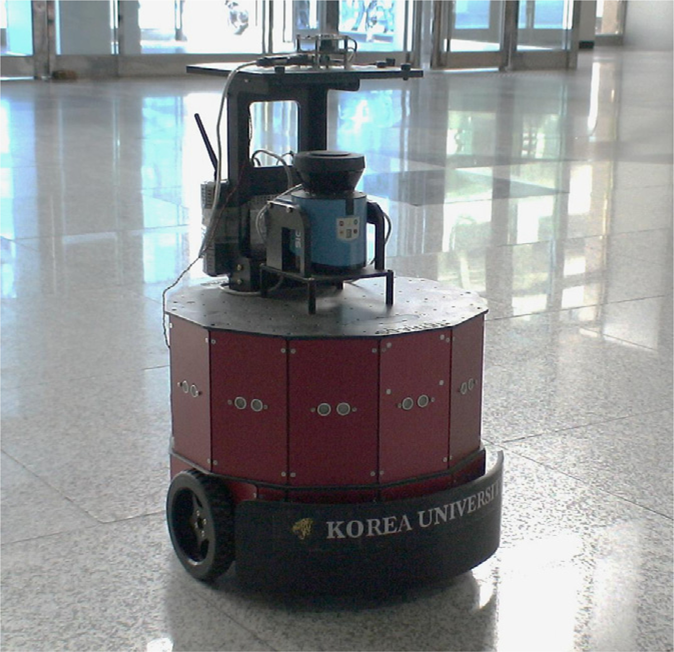
The robot used in experiments.
In order to evaluate the systematic odometry calibration of the proposed scheme, we carried out the experiments and compared the performances. The robot was driven in an open loop along a 4mx4m square path in CW and CCW directions. To minimize the non-systematic errors due to the environmental condition, the robot was made to travel slowly at 0.2m/s five times. The robot's initial and final absolute poses were fully utilized by the calibration equations of UMBmark method [1] and the proposed method. In a successful odometry calibration, the final position after calibration would converge to the initial position. The pose distributions of the CW and CCW runs are the result of non-systematic errors. Before calibration, the final position errors were 2.84m / 1.57m (CW / CCW) and the final orientation errors were −53.84°/ −36.39° (CW / CCW). The proposed scheme required relatively accurate measurements of the robot's orientation in the experiments. In order to measure the robot's experimental heading errors, a commercial on board compass can also be available. From the final position and orientation errors of the robot, the kinematic error parameters of Eb and Ed were estimated. The calibration equations in eqs. (10)–(11) were used by the proposed scheme to estimate the kinematic parameters.
In addition, the performances of the two calibration schemes of Bostani [11] and Lee [17] were compared.
The values of the kinematic error parameters from the four calibration experiments are listed in Table 3. The four calibration schemes gave different values of the kinematic error parameters. In order to validate the accuracy of these values, the robot was driven along the same 4mx4m square path 5 times in CW, CCW directions, respectively.
Kinematic error parameters from UMBmark method, Bostani's method, Lee's method and Proposed method.
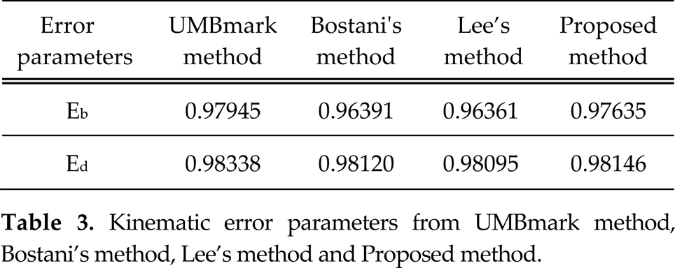
Kinematic error parameters from UMBmark method, Bostani's method, Lee's method and Proposed method.
Fig. 8 and Table 4 show the final position errors of experiments. Each calibration scheme reduced the final position errors of the test track in both directions. The average final position errors were 0.44m (UMBmark), 0.26m (Bostani's), 0.16m (Lee's) and 0.03m (Proposed), respectively.

Comparison of the final position errors for 4mx4m test track (UMBmark method / Bostani's method / Lee's method / Proposed method).
Compared with the other methods, the proposed method significantly decreased the final position errors. The final position errors of five runs in both directions were within 0.1m. The odometry accuracy of the proposed scheme was 14.7 times higher than that of [1], therefore, the proposed calibration scheme is advantageous over the previous calibration schemes.
Fig. 9 compares the odometry errors of the final position from the experiments. Odometry accuracy was remarkably improved by the proposed calibration scheme.

Comparison of the final position errors.
Results of the odometry accuracy after calibration.

In order to evaluate the effectiveness of proposed calibration scheme, we designed a 11.5mx5.8m rectangle test track. The robot was manually controlled to move the test track 3 times in the CCW direction at 0.2 m/s. The robot position was estimated from the calibrated odometry.
Fig. 10 shows the experimental results. Without calibration, the average final position error of the 3 runs was large (7.82m), as shown in Fig. 10 (a). After calibration, the final position errors were reduced to 0.97m (UMBmark method), 0.33m (Bostani's method), 0.19m (Lee's method) and 0.05m (Proposed method), respectively. The odometry accuracy was remarkably improved by the proposed calibration scheme within 0.1m errors of the robot's final position. The experimental results showed that the calibration accuracy of the proposed scheme was the highest of the four methods.

Comparison of the odometry accuracy among four calibration schemes (UMBmark / Bostani's / Lee's / Proposed).
Recently, the application area of service robots has been expanding in [20]-[25]. This paper proposed a calibration scheme to improve the odometry accuracy of a two-wheel differential mobile robot to overcome the limitations of conventional calibration scheme [1]. The new calibration equations use the robot's final orientation errors of a test track. The proposed equations remarkably reduced the approximation errors of the calibration equations in [1]. Furthermore, the proposed scheme considered the coupled effects between wheel diameter error and wheelbase error of the test track in the calibration experiments. The numerical simulations and experimental results showed that the proposed scheme improved the odometry accuracy significantly.
Footnotes
6.
This research was supported in part by the MKE(The Ministry of Knowledge Economy), Korea, under the Human Resources Development Program for Convergence Robot Specialists support program supervised by the NIPA (National IT Industry Promotion Agency) (NIPA-2011-C7000-1001-0005). This work was also supported in part by the National Research Foundation of Korea(NRF) grant funded by the Korea government(MEST)(2011-0016225). This research was also supported in part supported in part by Basic Science Research Program through the NRF funded by the MEST (2011-0025980).