
Abstract
Exploration of polar regions is of great importance to scientific research. Unfortunately, due to the harsh environment, most of the regions on the Antarctic continent are still unreachable for humankind. Therefore, in 2011, the Chinese National Antarctic Research Expedition (CHINARE) launched a project to design a rover to conduct large-scale scientific surveys on the Antarctic. The main challenges for the rover are twofold: one is the mobility, i.e., how to make a rover that could survive the harsh environment and safely move on the uneven, icy and snowy terrain; the other is the autonomy, in that the robot should be able to move at a relatively high speed with little or no human intervention so that it can explore a large region in a limit time interval under the communication constraints. In this paper, the corresponding techniques, especially the polar rover's design and autonomous navigation algorithms, are introduced in detail. Subsequently, an experimental report of the fields tests on the Antarctic is given to show some preliminary evaluation of the rover. Finally, experiences and existing challenging problems are summarized.
Introduction
Exploration of the polar regions is of great importance for research on global climate change and the evolution of the earth. It has therefore drawn more and more attention from all over the world in recent years. However, the harsh environment, e.g., low temperature, fierce wind and strong ultraviolet radiation, has kept humankind's footprint away from most of the polar regions. In recent years, the concept of roboticized polar exploration, i.e. using mobile robots to replace human operators in real exploration activities, has been reported in several scenarios. Some prototype polar rovers [1, 2, 3] have been developed and deployed on the Antarctic. For the polar robots, survivability and mobility are basic prerequisites. Besides, autonomy is also required because of communication restrictions. The problem of autonomous navigation has been well studied in recent decades. Autonomous vehicles, such as Stanley [4], Sandstorm [5], KAT-5 [6] etc. in DARPA Grand Challenge (DGC) 2005 and AMOR [7], MuCAR-3 [8], etc. in European Land-Robot Trail (ELROB) 2007, have demonstrated extraordinary autonomy in off-road scenarios. However, due to the limitations imposed by the harsh environment, previous polar robots only had limited autonomy at relative low speed.

Final target for the rover is to conduct scientific surveys at the 160×100 km2 area of Amery Ice Shelf (69.75°S, 71.0° E)
The polar rover Nomad [9] was developed by Carnegie Mellon University to search for meteorites. The rover was equipped with a differential global positioning system (D-GPS) for waypoint navigation and a LiDAR (Tight Detection And Ranging) for obstacles detection. Obstacles were detected by fitting a line to the LiDAR scan. The rover successfully discovered several meteorites when deployed on the Antarctic in 2000. The maximum and nominal speeds of Nomad were 0.5 m/s and 0.15 m/s respectively. The Cool Robot [10], a four-wheel-drive, solar-powered robot, was developed for polar instrument networks deployment by the Dartmouth College. The rover was only equipped with a GPS for localization and waypoint following. The rover was unable to detect and avoid obstacles. The average speed of the robot was 0.78 m/s on soft snow. MARVIN I and MARVIN II [11] developed by University of Kansas also adopted a LiDAR for obstacle detection and avoidance. No detailed descriptions on the autonomy and the navigation speed were reported. Another rover, Yeti [12], was developed by Dartmouth College to conduct surface-deployed ground-penetrating radar (GPR) surveys. It was able to detect the subsurface hazards across polar ice sheets. The autonomy of Yeti was achieved only by GPS waypoint following. The average speed of the rover was 1.1–1.8 m/s.
In 2011, the CHINARE has launched the project of developing a polar rover to conduct large-scale scientific surveys. Tor the polar rover, mobility and autonomy are most important due to the specific and harsh environments. As for mobility, the polar rover should be designed to reliably traverse the snowy and icy terrain. As for autonomy, the rover should be able to conduct large-scale scientific surveys autonomously or semi-autonomously in limited time. Different to previous rovers, fast-autonomy, i.e., autonomous navigation at relative high speed, was required for the rover to cover the large-scale area as fast as possible. However, due to the limitations imposed by the tough environments, most of the existing navigation algorithms could not be used directly. Therefore, some new concepts and algorithms have been proposed. These concepts of the polar rover was validated on the Antarctic during the 28th CHINARE in 2011–2012.
This paper is organized as follows: the rover design criteria is firstly defined based on the mission requirements and environmental challenges in section 2. Then, basic system components, including both hardware and software, are designed and implemented in section 3. Considering the environment features, both reactive and deliberative autonomous navigation algorithms are developed in section 4. Preliminary field test results, including survivability, mobility and autonomous navigation, are presented in section 5. Conclusions and future works are drown to enhance the rover in section 6.
Mission Specification
In 2011, the CHINARE has proposed the project of developing a polar rover to conduct large-scale scientific surveys on the Antarctic continent.
As shown in Fig. 1, the rover is required to carry out scientific exploration at the 160×100 km2 area of Amery Ice Shelf autonomously or semi-autonomously. Scientific research includes collecting GPR and meteorological data, and sampling ice and snow. To cover this large area, the rover is planned to move along a ‘Z’ shape path. That is, the support vehicle, which carries the Remote Control Station (RCS), moves along the centreline of the area. The support vehicle stops at specific sites and waits for the rover. The rover moves from the support vehicle to the predefined targets and then returns to the support vehicle to refuel and recharge. In this scheme, the rover should cover all of the area in 90 days (during one summer expedition).
Environmental Challenges
The Antarctic mainland is renowned for its harsh environment, especially low temperatures, ultraviolet radiation, strong winds, dry climate and geomagnetic field. Fig. 2 is a satellite image of an ice shelf taken in summer. The whole region is seemingly flat but includes lots of diverse terrains.

Example satellite image of the ice shelf

Diverse terrains of the Antarctic
As shown in Fig. 3 (a), most of the region is covered by snow and ice. Underlying rocks may be exposed to the air because of the melting of the snow. To traverse the snowy and icy terrain, the rover was required: 1) to be watertight to protect onboard electronics; 2) to be light-weighted and have large contact with the ground in order to prevent getting stuck in the snow. As shown in Fig. 3 (b), the ice cracks are even more challenging. The width of the ice cracks ranges from centimetres to metres. Some ice cracks, especially the cracks covered by snow, may be deadly for human and rover. To ensure safety, the human operator of the rover should avoid traversing the fractured area. The rover was also required to reliably detect and avoid apparent ice cracks. Besides these typical terrains at the test sites, the rover also had to traverse muddy and gravelly road, as shown in Fig. 3 (c) and (d), to get to the test site.

Typical man-made and natural obstacles
Besides traversing diverse terrains, the rover was also required to detect and avoid obstacles. As shown in Fig. 4, typical obstacles included man-made obstacles, such as containers, oil tanks, etc., and natural obstacles, such as rocks, snow drifts, ice cracks, etc. From these photos, most parts of the Antarctic are clear, without any obstacles. If obstacles exist, they are distributed in a scattered manner.

Rugged surface of the snowy ground
Another environmental challenge was discovered during the real field tests. Misled by available photos and videos, the Antarctic ground was supposed to be soft and smooth when designing the rover. This assumption is true only after new snow has fallen. However, the ground is hard and bumpy in most cases, as shown in Fig. 5. This is mainly caused by the repeated melting and freezing process of the snow. The rover suffered from severe vibration when travelling on this kind of terrain. The vibration posed severe problems in relation to the sensing accuracy of the equipped sensors, and thus deteriorated the fast autonomy of the rover robot.
Besides environmental challenges, some other crucial problems should also be considered. To deploy the rover to the test site, the rover had to be transported in a standard 20-inch container by ship and helicopter. Therefore, the rover should be of small size and light weight. The time and researchers were also limited because of the CHINARE schedule. Only three researchers were scheduled to finish the design and development of the rover in five months. The field tests were conducted by two researchers in 30 days.
Considering the mission requirements and environment challenges, some basic criteria of the rover was proposed:
Dimensions and Weight: ≤4×2×2 m(L×W×H), ≤800 kg, ≤10 kPa ground pressure.
Mobility: average speed 10 km/h, maximum speed 20 km/h, 20° gradeability, 0.15 m obstacle negotiation, 100 km cruise range. The rover should be able to adapt to snowy and icy ground, gravelly road, muddy road, shallow puddles, etc.
Operating Temperature: −20∼30°C. The 30°C was required for domestic tests.
Communication: 14.4 kB/s data rate. To enable tele-operation, 5 PAL images are required to transmitted to the RCS every second.
Operation Modes: human operation, tele-operation, semi-autonomous navigation and autonomous navigation. These operation modes discriminate from each other by the extent of human interference. Human operation was reserved to drive the rover to the test site.
Payload Capability: GPR, meteorological sampler, miniature driller, small–size manipulator.
Robustness and Simplicity: As the rover is expected to serve the CHINARE, the rover should be robust and easy-to-use. All the onboard hardware should be able to survive the harsh environment of the Antarctic. The algorithm implemented should be simple and effective. The user-interface designed for the operator should be friendly and easy-to-use.
With these design criteria in mind, a prototype of the polar rover was designed and implemented. The rover was deployed on the Antarctic during the 2011–2012 CHINARE. Field tests on environment survivability, mobility, GPS waypoint following and autonomous navigation have demonstrated the capability of the rover.
Rover Design and Implementation
Hardware System
In this section, the hardware system of the rover, including rover chassis, sensing and navigation, computing and control, communication system and scientific sensors, is introduced.
Rover Chassis
Instead of building the rover from scratch, a commercially available all-terrain vehicle (ATV) was chosen as the chassis of the rover to ensure reliability. When choosing the vehicle, some special requirements were taken into consideration: small size, light weight, reliability at low temperature, terrain adaptivity, all-wheel-drive (AWD), delivery time and accessory stock. With all these considerations in mind, the RANGER RZR S ATV from Polaris was selected as the chassis. The weight of the 2.69×1.53×1.79 (LxWxH) m ATV was 454 kg. The rugged design and field applications have guaranteed the reliability and off-road performance of the ATV. The four-stroke twin cylinder engine with 760 cc High Output provides enough power to surmounts various terrains. The AWD system offers extra assistance when moving on slippery ice and snow. Some other features have also been proven to be essential for the rover. The 300 mm dual A-Arm suspension system greatly suppressed the vibration of the rover. The automatic transmission, simple steering wheel and linear gears of the ATV greatly simplified the drive-by-wire modification.
To further augment the mobility, especially on ice and snow, four triangular tracks from Mattracks were added to the rover instead of wheels. The ground clearance of the vehicle was increased by 152 mm after equipping the tracks. The 0.991×0.279 m (LxW) tracks increased the ground contact area by approximately four times. The ground pressure of the rover was reduced to 1/3 of the original vehicle. The decreased pressure prevented the rover from sinking into snow. The tracks also exerted three-time gear reduction on the vehicle.
To protect the onboard hardware from water, snow and low temperature, a custom-built shield was built on the chassis. All the connectors exposed to air were connected by waterproof connectors. To make the rover conspicuous on the snowy ground, the shield was painted orange. The original and modified rover is shown in Fig. 6
Sensing and Navigation
To enable autonomous navigation, the rover should be able to acquire information about the surrounding environments and its posture. Primary onboard sensors included a LiDAR (Light Detection and Ranging) and a dual-antenna Integrated Navigation System (INS).

The original vehicle and modified rover
As discussed in [13], monocular and stereo cameras are not suitable for polar regions because of the featureless environments. Due to the low temperature, conventional LiDARs, such as Velodyne and HOKUYO LiDARs, were not suitable for the rover. An outdoor LMS-511 LiDAR from SICK was employed because of its industrial proven performance. Due to multi-echo technology, the versatile LiDAR presented outstanding performance in adverse environmental conditions. The IP67 enclosure provided superior protection against snow and water. The onboard heater further extended the operating temperature to −30. The LiDAR could output measurements at 100 Hz with 0.667° angular resolution. Initially, the rover was designed to navigate to targets by a reactive navigation algorithm. When tested at home, one LiDAR could provide sufficient measurements for reactive navigation. Only one LiDAR was prepared for the field test on the Antarctic. The LiDAR was tilted down to look at approximately 10 m from the rover.
As the rover had to conduct large-scale surveys, D–GPS was not suitable because of the communication limit. To augment the accuracy of the rover posture, a dual-antenna INS XW-ADU5630 from StarNeto was employed. The INS, though low-cost, could provide measurements of the GPS coordinates, attitude (including yaw, pitch and roll) and velocities (east, north and up velocities) at 100 Hz. The dynamic yaw and pitch error was 1°. The heading error was further improved to 0.2° by the dual-antenna GPS. The positioning error of the INS was 2 m without differential correction. The error of the velocity measurements is 0.02 m/s (1σ). Magnetic compass, which was commonly utilized in combination with the INS, was abolished because of the magnetic field on the Antarctic. Considering the fact that the Antarctic has no overhead obstacles and no GPS signal block out would happen, no other localization sensors were equipped on the rover.
Because of the limited time and staff, the drive-by-wire modification of the vehicle was done by Pronto4 Agnostic Autonomy System [14].

The Pronto4 Agnostic Autonomy System with Steering Ring
As shown in Pig. 7, the system could convert a vehicle to unmanned system with little mechanical efforts. The Pronto4 system has integrated high-level control algorithms such as velocity control and GPS waypoint following. Nevertheless, the algorithms require specific hardware. For the rover, only the mechanical design and motors of the system were utilized. The system was only responsible for executing motor commands issued by the navigation system.
As for the computing system, only one embedded automation computer from Advantech was employed. The computer was chosen for its low temperature performance, low power consumption, compact size, rugged design and industry-proven reliability. The embedded computer had only one Pentium M CPU (1.4 GHz) and 512 MB DDR RAM on it. The computing power of the computer was sufficient for the reactive navigation algorithm. However, the computer was nearly exhausted when adopting deliberative navigation algorithm during the field tests. As the rover was initially designed only for reactive navigation algorithm, only one computer was equipped on the rover.
As the rover only had limited autonomy, communication systems were equipped to monitor and tele-operate the rover. Two communication systems were integrated to fulfil different requirements. For short-range communication, about 0–200 m, two wireless access point (AP) EKI-6311GN from Advantech were employed. With the help of these two APs, the operator could remotely login to onboard computers to modify algorithms. For mid-range communication, about 0–10 km, independent communication links were established for transmitting data and video. As for video transmission, a video transmitter of VVLINK-C2000-TX and a video receiver of VVLINE-C4000-RX from VIGA were chosen. The transmitter could transmit 6 PAL images every second. Communication modules of MDS EL7052 were used to transmit data between rover and remote control station.
Besides short-range and mid-range communication systems, another two long-range, about 0–50 km, communication systems have also been tested in 2014. One system consists of two military radio modems. The modems could cover 50 km range. The data rate of the modem is 14.4 kB/s. The modem could transmit 6 PAL images every second. Because of the obstruction of the earth, one modem had to be raised to 300 m into the sky by a helium balloon. The cost of the balloon and necessary devices to fly the balloon is extremely high. Two satellite communication systems have also been tested. The Iridium satellite communication system could ensure global coverage. To establish point-to-point communication, a VPN sever is required. The tested bandwidth is 0.75 kB/s. Besides, the communication is not so stable. Data link may be disconnected by clouds over the antenna. Though the communication devices is not so expensive, the communication fee is so high that the project budget could not afford. Maritime satellite communication provided by Inmarsat was also tested. Compared to Iridium satellite communication system, the maritime communication system has advantages in several aspects: the maritime system could provide much broader band while cost much less; direct point-to-point communication could be established between different communication terminals; robust data link could be ensured even with the presence of overhead clouds. Tests at home have suggested that 8 kB/s bandwidth could be ensured by the system. The only drawback of the maritime communication system is that the system could not cover the South and North Pole. Fortunately, the area for the rover to explore is completely covered by the maritime communication system.
Scientific Sensors
Besides equipments for the autonomous navigation, payloads were also considered when designing the rover. Instead of building an omnipotent robot, the rover was designed as a platform that could provide support for other equipments such as GPR, miniature driller, multi-functional meteorological sampler and small-sized manipulator. The rover was responsible to supply power and communicate with these payloads. In Fig. 8, one GPR was equipped on the rover. To shield the antenna from electromagnetic interference induced by the rover, the GPR antenna was mounted in a sledge dragged by the rover.
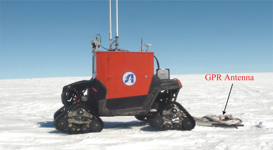
The rover the payload GPR
As shown in Fig. 9, all these devices were integrated together to build the rover system.

Onboard hardware system of the rover
The vehicle itself was powered by gasoline engine. Besides perception system and computing system, miscellaneous devices, including batteries, a PAL camera, video transmitter, data radio, ethernet switch, etc., were also equipped on the rover. The onboard electronics were powered by the 110 V Li-ion batteries, which were charged by the vehicle generator. The batteries, together with a DC to DC converter could support the electronics for at least 8 hours. The camera was only used for video surveillance. The power relays were responsible for controlling power supply to onboard devices and key-on, start-up operation of the vehicle. The devices exposed to the outside, such as INS, LiDAR and camera, were all designed for outdoor applications. To ensure reliability, the other electronic devices were sealed into two waterproof cases to protect them against water and low-temperature.
To ensure real-time performance, reliability and maintain friendly user interface, a hybrid software architecture was developed. The onboard software was developed in QNX to ensure real-time performance and reliability while the RCS was developed in Windows to achieve easy-to-use user interface.
As shown in Fig. 10, multi-thread and multi-process architecture was adopted in the QNX software system. In the chart, each oval module represents one process. Data flow is indicated by arrows. To ensure reliability, each process was responsible for only one task. Inter process communication (IPC) was done by shared memory in our implementation. The communication between process and hardware was specified by hardware, either by TCP/IP or RS-232. Communicator module was responsible to exchange data with RCS. Control commands, such as target GPS coordinates, power relay switch and payload operation, were received from RCS to control the rover. Rover status information was transmitted to RCS.
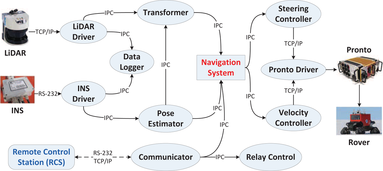
Multi-thread and multi-process architecture was adopted in the QNX software

Remote control station was built in Windows to provide friendly user interface
As shown in Fig. 11, the RCS was built in Windows to provide friendly user interface. Google Earth was integrated into RCS. The operator could set targets on the Google Earth. The rover trajectory was also displayed. Video image transmitted from the rover could be displayed and recorded by RCS. The status of the rover, such as velocity, heading, yaw, pitch angles etc., was visualized by Qt widgets. Racing wheel and wireless gamepad from Logitech were employed as controllers. Control signals, including steering, throttle, and brake, were sampled by DirectX SDK and then transmitted to the rover. In this way, the rover could completely follow the manipulation of the operator. Other parts of the RCS, including communication status, power relay control and payload control, were also integrated in the RCS.
The problem of high-speed autonomous navigation has been well-studied in recent years. However, autonomous navigation of the polar rover had to be specialized in the following points:
Obstacle Distribution: Most parts of the mainland are clear of obstacles. Existing obstacles are distributed in a scattered manner.
Hardware Limitation: Low temperature of the Antarctic imposes limitations on the onboard hardware, especially onboard computers and sensors. The featureless environment also limits the usage of monocular and stereo camera.
Robustness and Simplicity: The navigation algorithm should be robust to safely navigate the rover to the targets. Simplicity is required because of the time limit and hardware limit.
Rugged Terrain: Rather than soft and smooth, the ground of the polar region was hard and rugged. The attitude of the rover changes drastically when travelling on the ground at relative high speed (approximately 10 km/h).
When designing the rover, the researchers had no idea of the rugged terrain. Considering the obstacle distribution and limited hardware, reactive navigation was initially designed and implemented. However, the reactive navigation algorithm was problematic when tested on the Antarctic due to the vibration induced by the rugged terrain. Deliberative navigation based on environmental models was implemented during the field tests. Both the reactive and deliberative navigation algorithms are discussed in this section.
Reactive Navigation Algorithm
The reactive navigation algorithm was implemented based on vector field histogram (VFH) [15] algorithm. The VFH algorithm assumes that there exists virtual force field around the moving robot. The obstacles exert repulsive force on the robot. Nevertheless, the target applies attractive force on the robot. The sum of the repulsive and attractive force indicates the desired heading direction.
The reactive navigation algorithm first identifies obstacles based on measurements returned by the LiDAR. With the assumption that the ground is smooth, the obstacle detection process is demonstrated in Fig. 12.
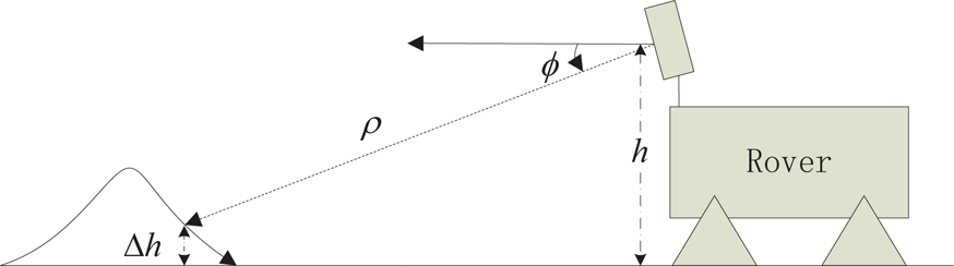
Obstacle detection
The tilt angle of the LiDAR relative to the rover is φ. Each scanner measurement consists of distance measurement ρ and corresponding scanning angle θ. With the assumption that the ground is flat, the obstacle height relative to the ground is:

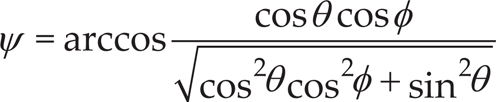
If the relative height exceeds predefined threshold Δ th , the corresponding scanning angle θ is identified as an obstacle angle with respect to the LiDAR coordinates. The obstacle angle is then projected into the vehicle coordinates:
The original VFH algorithm ignores the kinematics of the non-holonomic vehicle. To adapt the VFH algorithm to the Ackerman steering rover, the identified obstacle is expanded as shown in Fig. 13.
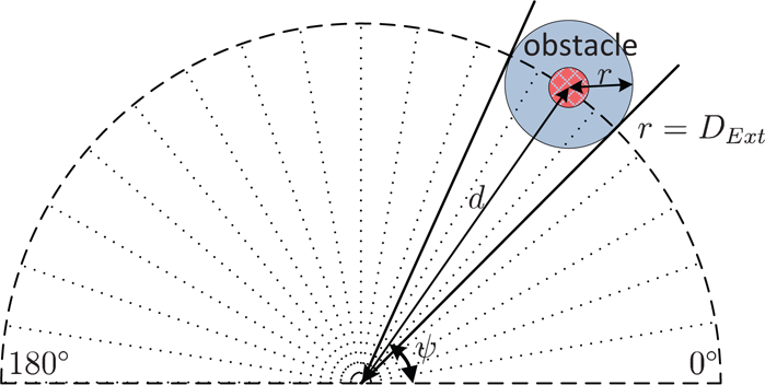
Obstacle expansion
The detected obstacle, as denoted by the red circle, is expanded by a guarding distance D Ext . The distance between the obstacle and the rover is:

The obstacle angle is also extended by the guarding distance to

The attractive force exerted by the target at angle ψ is defined as:

where ψ Target is the angle pointing to the target. The extra 1.0 is applied to prevent minus attractive force.
Based on the repulsive force introduced by the obstacle and the attractive force exerted by the target, the overall pass function for angle ψ is:

The angle with maximum pass value is selected as the desired heading angle ψ d . The rover is steered to heading to the angle. The corresponding desired velocity is:

where the vmax and vmin are the expected maximum and minimum velocity, respectively.
When tested on the Antarctic, the reactive navigation algorithm could effectively avoid obstacles. However, because of the vibration induced by high-speed movement, the algorithm sometimes misidentified smooth ground as obstacles. Detail is discussed in section 5.5.2. To solve this problem, a deliberative navigation algorithm based on the environmental model was implemented and tested during the field tests.

Flowchart of the deliberative navigation algorithm
The flowchart of the deliberative navigation algorithm is shown in Fig. 14. Compared with the reactive navigation algorithm that relies on instantaneous environment measurements, the deliberative navigation algorithm navigates the rover by accumulated environmental models.
To build a local consistent environmental model, the LiDAR measurements are first transformed to the reference coordinate system:
where L, V, R denote the LiDAR, vehicle, and reference coordinate system respectively, L P denotes the LiDAR measurements in L, L V R and V R R denote the rotations from L to V, V to R respectively, V O L denotes the origin of L in V, R O V denotes the origin of V in R, R P denotes the coordinates of the point cloud in R. The rotation L V R and translation V O L could be acquired by calibration process. The rotation V R R could be resolved by the heading, pitch and roll angles measured by the INS. Due to the hardware limitation, an accurate position is unavailable. Considering the fact that the velocity error is only 0.02 m/s (1σ) while the positioning error of the INS is 2 m, the translation R O V is estimated by integrating the velocity measurements over time. In this scheme, the relative local positioning error is guaranteed to be small in a specific time window. The resultant environmental model is precise enough for identifying obstacles.
The environmental model implemented on the rover was wrappable elevation grids [16]. Elevation grids were utilized for its low complexity and easy to implement. Special considerations were taken to adapt the original elevation grids to the rover. Each LiDAR measurement in referenced coordinate system is first assigned to a grid specified by its x,y coordinates. Then, the grid elevation information is updated by the measurement elevation z. In each grid, which covers 0.2 × 0.2 m2 in our implementation, the highest elevation e max , lowest elevation e min , and average elevation e are all recorded. The highest and lowest elevations stored in the grid are updated only if new elevation exceeds the recorded information. The average elevation is always updated with each new measurement.
During the field tests, there were some grids that have no measurements. Outstanding obstacles may block the LiDAR measurements and result in null grids. The only LiDAR could not cover all the grids because of the high-speed movement and drastic attitude change. Interpolation technique is adopted to tackle these null grids. The interpolation of null grid g could be expressed as:

where Adj(g) denotes the adjacent 8 grids of grid g, e ij represents the elevation of grid g ij . Let n ij denotes the number of measurements falling in g ij . If n ij is not 0,1 (n ij ≠ 0) equals to 1 and vice versa.
The interpolation did effectively interpolate null grids. However, it may be problematic considering the ice cracks. The inner part of the ice cracks is lower than the surrounding edges. Occluded by the edges, the ice cracks may have no measurements falling in it. Simple interpolation may obscure or even eliminate the narrow ice cracks. To solve this problem, the interpolated elevation e is verified based on the hypothesis that the surrounding grids are higher than the ice cracks:

where Δ ij = h max − h min is the difference between the highest and the lowest points of grid g ij . If α = 0.95, then:
where σ ij indicates the reliability of the elevation estimation of surrounding grid. It could be set based on the number of measurements falling in the grid. This inequality means that the interpolation is accepted with a belief of 95% if the interpolated elevation is lower than e ij − Δ ij + 1.64σ ij .
To navigate the rover on the environmental model, the environmental model should be further analysed to identify obstacles and evaluate traversability. The position of the rover is evaluated by integrating velocities. The resultant environmental model is relative accurate only in local area. The traversability could only be evaluated based on the relative elevations. In our implementation, two kinds of traversability cost, in-grid traversability cost T IG and oct-area traversability cost T Oct , are evaluated.
For each grid, the in-grid traversability T is evaluated based on the difference of the highest and lowest elevation:

where th IG is the threshold to identify in-grid obstacle. The in-grid traversability is normalized to 0–100.
The oct-area traversability cost is evaluated by comparing the difference between the grid elevation e and the surrounding eight grid elevations e ij . The oct-area traversability cost of g with respect to g ij is:

where th Oct denotes the threshold for obstacle identification in the neighbouring eight grids. The oct-area traversability cost is also normalized to 1–100. The final oct-area traversability cost of the grid is simply set as the highest of the eight costs.
To ensure safety, the final traversability cost is conservatively set as the maximum of the in-grid and oct-area traversability cost as:
The higher cost means it is harder for the rover to traverses the grid. The traversability cost of each grid is further extended to a security area to treat the rover as a point when planning a path on the environmental model.
To plan a trajectory on the environmental model, candidate trajectories are first generated off-line. Then, desirable trajectory is selected for the rover to track. Because of the sparse obstacle distribution and limited computing resources, the candidate trajectories are generated by sampling the steering angle of the rover. For each candidate trajectory, it is abandoned if it encounters an obstacle grid. Then, each trajectory is evaluated by the path traversability cost C PTC and the target approaching cost C TAC .
The path traversability cost is resolved by averaging the traversability cost of all the grids on the path. Thus, a higher C PTC indicates rougher path. To navigate the rover to the operation sites specified by GPS coordinates, the target approaching cost of each path is also evaluated. The C TAC of each path is proportional to the difference between the path direction and target direction:

where ψ VT denotes the direction from the rover to the target, ψ VL denotes the direction from the rover to the last point of the candidate trajectory. The definition is illustrated in Fig. 15.
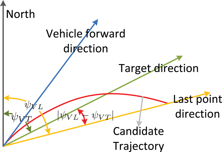
Target approaching cost illustration
The target approaching cost is also normalized to 1–100. A lower cost indicates the path approaching the target faster.
The path traversability cost and target approaching cost are synthesized to get the overall cost of the path:

where w PTC and w TAC are the weighting factors and w PTC + w TAC = 1. The different settings of these two factors result in varying navigation performance. Higher w PTC introduces a smoother path, while higher w TAC indicates that a more aggressive path towards the targets is preferred.
To track the selected trajectory, the steering wheel is set according to the steering angle of the selected trajectory. The desired velocity to execute the trajectory is inversely proportional to the path traversability cost. The velocity is controlled by a PID controller. To avoid frequent adjustment, the velocity tolerance is set to 0.5 m/s.
The prototype of the rover was deployed and tested on the Antarctic during the 2011–2012 28th CHINARE. Two test sites, the site near Chinese ZhongShan Station at 69.373477° S, 76.370791° E and the site near the Russian airport at 69.429735° S, 76.342142° E, were selected to test the rover. About 40 short-range (less than 1 km) test runs were carried out near the ZhongShan station to verify the navigation algorithm and test the survivability and mobility of the rover in 15 days. About 20 mid-range (about 0–10 km) test runs were conducted on the ice shelf near the airport to test the long-range autonomous navigation and communication of the rover in eight days. To ensure safety, all test runs were carried out on breezeless and sunny days in the daytime. The rover parameters and field tests results are summarized in Table 1. Details will be discussed in the following part of this section.
Survivability
During the field tests, the rover demonstrated reliable survivability in the harsh environment. When designing the rover, the lowest working temperature was set to −20°C. The tested lowest lowest working temperature was set to −16°C on the ice shelf. Onboard sensors that were exposed to the air, including the LiDAR, INS and the camera, could function properly in this low temperature. The LiDAR could output valid measurements at −16°C with the help of an embedded heater. As there was no overhead obstruction, the dual-antenna GPS could find enough satellites, approximately six to eight, to locate and orientate the rover. Other electronics, such as computers, communication devices, batteries and motors, etc., were protected from low temperatures by a warm-keeping shield and suitcases. Together with the 28 operating temperatures tested at home, the tested operating temperature of the rover ranged from −16° to 28°. The waterproof shield and suitcases also effectively protected the onboard hardware from water snow and ice. As shown in Fig. 16, the rover survived a snow storm at the ZhongShan station. The fierce wind tore off the plastic shield. Some snow even slipped into the rover through narrow slits. The rover still functioned properly after cleaning up the snow.
Rover Parameters and Field Test Results

Rover Parameters and Field Test Results
The mobility of the rover was verified at different places. The climbing capability was verified at the slope near the Russian Progress Station by a human driver. The cruise range was limited by the fuel and battery capacity of the rover. Maximum speed, 36.58 km/h, was achieved by a human driver on snowy ground on the ice shelf. With the help of the tracks, the rover could get over 0.18 m obstacles. The terrain adaptivity was completely tested by human driver on the 40 km way to the airport. The rover had to traverse shallow puddles (about 500 m), icy road (about 1 km), muddy road (about 1.5 km), gravelly road (about 3 km) and snowy road (about 34 km) to get to the test site. The rover could overcome most kinds of the ground. However, as shown in Fig. 17, the rover driven by the human did get stuck once in the melt snow near the Russian Progress Station. Fortunately, the melt snow existed only near the sea. The low temperature at the airport guaranteed that there was no large area of melt snow. Adaptivity of snowy and icy ground was also validated by autonomous driving on the ice shelf. Two long-range autonomous navigations were conducted. One 10.2 km test run was carried out to autonomously navigate the rover to the south to test the performance of the mid-range communication system. The other 30.35 km test run was conducted to simulate execution of real tasks.

Exterior and interior of the rover after the snow storm

Front and rear view of the rover stuck in snow and ice
During the field tests, only the short-range and mid-range communication devices were equipped on the rover. The wireless APs provided an effective way to verify and modify navigation algorithms. To test the mid-range communication system, two 5 m antennas were set at the RCS. Two 2.7 m antennas were set on the rover. The tested communication was 10.2 km. The data rate of the mid-range communication system was 14.4 kB/s. The system could also transmit 6 PAL images from the rover to the RCS every second. The data and video radio could satisfy the communication needs between RCS and the rover during the field tests. To further improve the communication range, long-range communication systems were also tested in 2014 (as discussed in section 3.1.4).
Scientific Mission
During the field tests, only GPR was equipped on the rover to verify the applicability of the rover. Interfaces to other scientific payloads, such as meteorological sampler, miniature driller, and small-size manipulator, were reserved when designing and developing the rover. GPS waypoint following [17] was tested on the rover to simulate the execution of real tasks. As shown in Fig. 18, six target points were set for the rover to achieve on the ice shelf. The rover was commanded to travel back and forth between these points. The total distance of the overall task was 30.35 km.
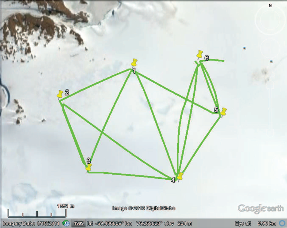
Trajectory of the rover in a simulated task
During the field tests, the front tracks squeezed the brake pipeline when the rover made sharp turns. The right pipeline broke during the last test. The rover always deviated to the right because of the imbalance of the brake force. The navigation algorithm then steered the rover to amend the error. As a result, the rover moved in an ‘S’ shape as shown in Fig. 19. The field tests were suspended as there was no alternative pipeline on the Antarctic.

The rover moved in ‘S’ shape because of the broken brake pipeline
Reactive Navigation
As discussed in section 4, reactive navigation was initially designed and implemented on the rover because of the sparse obstacle distribution. With the assumption that the ground was soft and smooth, obstacles could be detected based on instantaneous LiDAR measurements. However, when tested on the Antarctic, the algorithm turned out to be inefficient. About ten containers and three snow drifts existed at the test site near the airport. The algorithm did detect and avoid obstacles, especially outstanding obstacles. The algorithm also frequently misclassified flat ground as obstacles. This was induced by the incorrect assumption. The ground was soft and smooth only after new snow had fallen. In fact, the ground was hard and tough most of the time. The snow and ice were melted a little by sunlight during the day. Then, the melted snow and ice froze to ice during the night. This process could last for days. The ground turned to be hard and rugged as shown in Fig. 5. When the rover moved on the snowy and icy ground, the pitch and roll angles of the rover changed drastically. One typical example of the attitude change is shown in Fig. 20.

Because of the bumpy terrain, speed, pitch and roll angles of the rover changed drastically when travelling on the snowy and icy ground during the field tests on the Antarctic
The low-cost INS could not precisely capture the exact pose of the rover. The time difference between INS and LiDAR measurements made it even harder to reliably identify obstacles from instantaneous measurements.
Because of the false assumption, flat terrain was frequently identified as obstacle. Even after adjusting the threshold and compensating the attitude of the rover, this problem could not be reliably solved because of the drastic changes of the rover pose. Therefore, the rover wound around to avoid the non-existent obstacles even on flat ground. The reactive navigation was only tested for approximately 8 km because of the essential defects of the algorithm.
The reactive navigation algorithm failed mainly due to the lack of environment information, deliberative navigation algorithm based on accumulated environmental model was implemented during the field tests to solve this problem.
As discussed in section 4.2, both the highest and lowest elevations were stored in each grid. As shown in Fig. 21, the differences between the highest and the lowest elevations falling in each grid are calculated to highlight the terrain feature. The grid is set to 0.2×0.2 m2. The differences, represented by the grid colour, ranges from 0.0 m to 0.18 m. The shallow ditches formed by snow and ice could be clearly identified from the model. The figure also gives an intuitional view of the bumpy terrain.

Example environmental model of the typical terrain built by the rover in real-time
To verify the effect of the proposed interpolation algorithm, one example of the environmental model is given in Fig. 22.
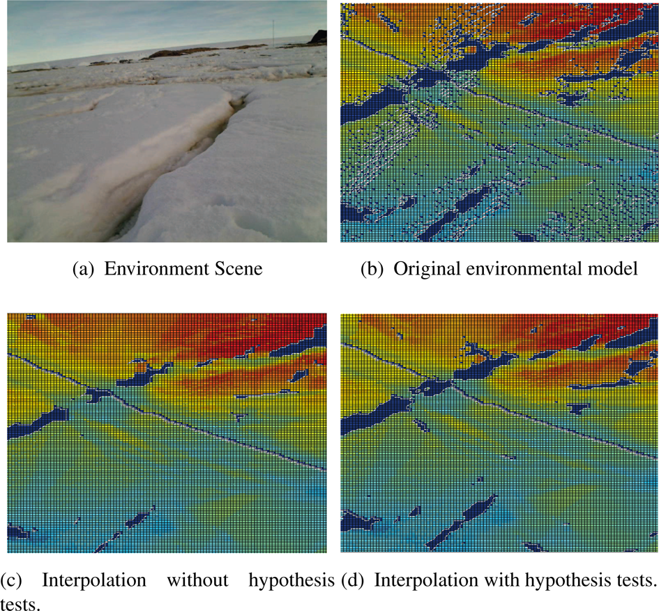
Environment scene and the environmental models
The data was collected on the sea ice as shown in Fig. 22(a). Ice cracks could be clearly identified in the photo. The original environmental model is shown in Fig. 22(b). In each grid, the average elevation is represented by corresponding colour. The blue grids have no measurements falling in. The blue line is reserved to indicate the trajectory of the rover. The blue patches are ice cracks that should not be interpolated. If interpolated without hypothesis test, ice cracks might be narrowed or even disappeared as shown in Fig. 22(c). If further tested by the hypothesis, as shown in 22(d), the ice cracks are retained while the sparse grids that have no measurements are also interpolated.
In our implementation, the environmental model was set to cover a 20×20 m2 area. The model was updated by each new LiDAR measurement. The traversability analysis and path planning were done 5 times per second. The candidate trajectory tentacles were 5 m long. With these settings, the rover could reliably detect and avoid obstacles when tested on the ice shelf. Deliberative navigation algorithm has been tested for approximately 15 km. The maximum and average speeds were 5.32 m/s (19.14 km/h) and 3.1 m/s (11.16 km/h) respectively. Considering the fact that the average speed of snowcat driven by human is approximately 10 km/h, the high-speed navigation is satisfying.
Even though the deliberative navigation algorithm could reliably navigate the rover, some problems remain to be solved. Firstly, the onboard embedded computer was not powerful enough to reliably run the deliberative navigation algorithm. The computer was initially prepared only for the reactive navigation algorithm. When applied to the deliberative navigation that required much more computing power, the computer was nearly exhausted during the field tests. This could be solved by equipping the rover with more computers. Secondly, some grids might still have no elevation values even after interpolation. This was induced by the lack of LiDAR measurements. Only one LiDAR was prepared for reactive navigation when designing the rover. The only LiDAR could not provide sufficient measurements during sharp turns at high-speed. However, this problem could be solved by adding more LiDARs.
In this work, a prototype of the polar rover for large-scale scientific surveys was developed. The main concerns of this paper are twofold: the mobility and the autonomy. For mobility, the rover was required to surmount the harsh environment and reliably traverse the diverse terrains. System design and implementation of the rover that could ensure reliable mobility are detailed described. For autonomy, both reactive and deliberative navigation algorithms were designed and implemented. In reactive navigation algorithm, obstacles were firstly detected based on instantaneous LiDAR measurements. Then, the rover was navigated to avoid these obstacles by vector field histogram algorithm. In deliberative navigation algorithm, models of the surrounding environments were firstly built in real time. Then, obstacles were detected by analysing the grid statistics of the environmental models. Optimal trajectory was selected from the candidate trajectories based on traversability cost and target-approaching cost. Finally, the rover was controlled to follow the optimal trajectory while avoiding obstacles.
During the 2011–2012 28th CHINARE, the rover was deployed and tested on the Antarctic. The survivability, mobility and autonomy of the rover were fully verified by the field tests. Field tests have suggested that the rover could surmount the harsh environment and diverse terrains. As this was the first high-speed ground mobile robot deployed on the Antarctic, very little about the terrain features was known beforehand. The rover was initially designed only for reactive navigation algorithm. The algorithm did detect and avoid outstanding obstacles during the field tests. However, due to high-speed navigation on the rugged terrain, the reactive navigation algorithm sometimes misidentified flat ground as obstacles. As a result, the rover wound around to avoid the nonexistent obstacles. Because of the inefficiency of the reactive navigation algorithm, deliberative navigation algorithm based on environment maps was developed and tested during the field tests. The deliberative navigation algorithm could reliably detect and avoid obstacles without misidentification. The total distance of autonomous navigation was approximately 23 km. The recorded maximum and average speed of the rover were 19.15 km/h (5.32 m/s) and 11.16 km/h (3.1 m/s) respectively. GPR was also equipped on the rover to evaluate the payload capability. Through these field results, survivability, mobility and autonomy of the rover were preliminarily verified. Besides, lessons on how to augment the rover in the future are also learned:
Mobility: The cruise range of the rover is only 40 km. To increase the cruise range to 100 km, the capacity of the fuel tank and the batteries should be enhanced. Besides, solar and wind energy could be utilized to extends the operation time of onboard electronics.
Autonomy: For the rover, only one LiDAR was equipped. The only LiDAR could not provide enough environment measurements for the deliberative navigation algorithm at high speed, especially during sharp turns. More LiDARs should be equipped on the rover to solve this problem. Accordingly, the computing system should also be upgraded to fulfil the requirements of the deliberative algorithm.
The ice cracks, especially those covered by snow and ice, are difficult to be detected by LiDARs. To ensure safety, these deadly ice cracks should be reliably detected. One possible solution is to equip real-time GPR in the front of the rover. The GPR could provide real-time measurements of underlying hazards. Another possible solution is scanning the area by a rotor flying robot equipped with GPR in advance. The flying robot could fly at very low altitude and thus could obtain information under the surface without contact.
Even with the autonomy of the polar rover, human intervention is still required to mediate uncertainties of the environment and execute complicated tasks. However, it is not possible to keep humans in the loop for a very long time. Both human intervention and autonomous operation should be implemented to complement each other. Research on what, where and how these two cooperate is also required.
Communication: The tested communication range was only 10 km. The range is limited by the communication devices and the occlusion of the earth. To increase the range to 50 km, new communication systems should be utilized. As indicated by the communication tests conducted in 2014, military radios with a helium balloon and maritime satellite communication system may solve the communication problem.
Footnotes
7.
This work is supported by State Key Program of National Natural Science of China (Grant No. 61035005).
The authors would like to thank all of the 28th CHINARE team members, Chinese Arctic and Antarctic Administration and Polar Research Institute of China for their support. The authors especially appreciate Fengming Hui from Beijing Normal University and Yubing Mo from Heilongjiang Administration of Surveying, Mapping and Geoinformation, for their help during the field tests.