
Abstract
A new method for calibrating a parallel robot is proposed as part of a project aimed at developing a calibration method for spacecraft docking mechanism motion simulator. To implement this method, a calibration equation is built by generating the constraint conditions of the end-effector's motion in the workspace using a three-dimensional coordinate measuring machine. According to the established calibration equation and the simulation, the geometrical parameters of the parallel robot are identified. The effectiveness of the calibration method with a coordinate measuring machine is verified through random pose test experiment.
Introduction
Parallel robots such as a Stewart platform [1] have some advantage of high rigidity, high accuracy, and high load-carrying capacity over serial robots. However, they have some drawbacks of relatively small workspace and very difficult forward kinematics problems. These robots have found a variety of applications in flight simulators, high-precision machining centers, medical surgery, and so on.
It is well known that excellent positioning performance of the manipulator may be achieved based on an accurate kinematic equation. However, parameters of the equation inevitably deviate from their nominal values due to manufacturing and assembly errors. A direct consequence is to reduce the accuracy of the robots, since their control strategy heavily relies on a precise description of the kinematic equation. One way to tackle this problem is to improve the theoretical kinematic equation through kinematic calibration which consists of identifying a more accurate geometrical relationship between the joint sensor/encoder reading and the actual pose of the end-effector. Literatures indicated that the most economical and feasible way of enhancing the manipulator accuracy is through kinematic calibration [2–5].
Let us employ the paradigm of literature [6] in stating a unified calibration formulation. First, the principle is to link the unknown kinematic parameters P and the information on the state of the manipulator M, either provided by sensors or through constraints applied on joints or brought by an additional mechanism. Some closed loop equations f(P, M)=0 can be determined; the equations vanish within the measurement error. The simplest way to determine M is by using the internal sensors of the manipulator. Usually though, as they do not provide redundant information, their number is minimal for controlling the manipulator's degrees of freedom. It is possible to install additional captors on passive joints for self-calibration (with the benefit of simplifying the forward kinematics) in [7], [8]. Alternatively, one can decrease the degree of freedom by constraining the end-effector or the mobility of some joints in [9–11]; this can also be used to simplify the calibration procedure if external measurements are present by several researchers [12], [13].
In practice, it is not easy to add redundant sensors or constrain. Hence, most calibration methods use external measurements devices to obtain the required information, such as laser trackers, theodolites, cameras, inclinometers or mechanical devices in [14], [15].
Many authors use the kinematics to relate the kinematic parameters P to the available information M. Then, the basic calibration methods with external measurements use either the forward kinematics or the inverse kinematics in [16–18]. Those calibration methods may be prone to error. The reason is the difficulty to obtain a closed form for the solutions of the kinematics problem. The work presented in this paper is at an early stage of development. The goal is to develop an effective calibration model for spacecraft docking simulator. Thus far, work has focused on developing a calibration model for the parallel robot because it is similar in form to a structure of spacecraft docking simulator. The remainder of the paper is organized as follows: In Section n, we present a new calibration scheme with error model. We describe our data measurement method in Section in. Simulation and experiment results are given in Section IV.
Calibration algorithm
Error Model
In this design, the parallel robot has 6 extensible legs that are connected by ball joints to the load platform and the base. The load platform ball joints are fixed in position relative to the load platform coordinate frame while the base ball joints are fixed in position relative to the base coordinate frame.
The error model allows for deviation in the ball joint positions and in the lengths of the legs, giving 42 error parameters in total. For the Stewart platform, the loop closure condition is given by (1). The meanings of the symbols in (1) may be inferred from Fig. 1.

The kinematic relation of the parallel robot

Matrix R is the 3 by 3 rotation matrix that converts the load platform basis vectors into the base frame basis factors. The inverse geometric solution expresses the actuator coordinates as a function of the endpoint position. And the direct geometric solution expresses the endpoint position as a function of the actuator coordinates robot geometry, and error parameters. While the direct geometric solution has been solved analytically, it is much more computationally to use a numerical solution algorithm such as the Newton-Raphson algorithm in [19], [20].
The differential solution expresses rates of change in the endpoint coordinates as a function of changes in the error parameters. If the error parameters are grouped into a single 42 by 1 partitioned vector as in (2) then the direct Jacobian matrix is defined as in (4).

Where


The terms in (4) are complicated to express or evaluated, but the loop closure equation (1) may be rearranged as (5) and the δl i collected into a vector function (6). It may be shown that
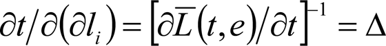
Hence

This is easier to evaluate.
In the following expression, the subscript represents the ordinal number of the measurement points. Each nominal measurement position
The objective of error identification is to know the effective kinematic parameters of the robot in order to control accurately the endpoint position. The relationship between the measured position of the robot endpoint PM and the actual position of the robot endpoint P is as follows (see Figure 1)
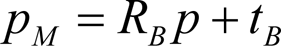
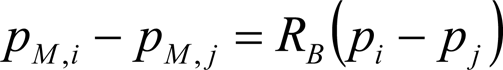
Where R B and t B are the rotation matrix and position vector from the measurement system coordinate to the robot base frame, respectively. The relative position between point i and j in workspace is
Let us consider that the actual position of the robot endpoint differs slightly from the nominal one p(n)

Then (10) becomes

The relative position of pM,1 and pM,0 is

If positions pM,i, pM,j and pM,0 lie on a plane, and the line pM,0 to pM,1 is perpendicular to this plane, we have

Then, from (12) and (13) we obtain

Denoting,

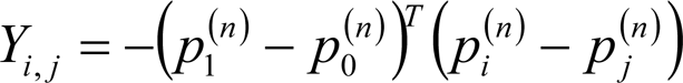
Then, (15) becomes

The above calibration equation is independent of RB and pB. If we measure n points, we have n-1 equations

Where


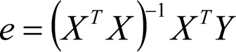
The least squares solution for e is
If E denotes the vector of original kinematic parameters, the updated kinematic parameter values are E obtained by

Since this is a nonlinear estimation problem, this procedure is iterated until the variation e approach zero and the parameters E have converged to some stable values. Perpendicular constraints between the plane and line can be obtained by coordinate measuring machine as explained in Section 3.
The simulations and experiments were also conducted using the parallel robot, which developed in the IEST, Harbin Institute of Technology, as shown in Fig. 2. The precise three-dimension coordinate measurement machine, manufactured by STAR Tech., was used to construct the constraint conditions in the workspace, as shown in Fig. 3. This machine has a repeatability of 0.011mm and an accuracy of 0.016mm in the 1.2m×1.2m×1.2m measuring range.

Experimental setup
Making constraints in the workspace using the 3-D coordinate measuring machine is as follows:
Pose the robot endpoint in the position of any range to be measured and read the positioning coordinate from 3-D coordinate measuring machine, via the computer.
Move the robot endpoints to the next position.
Move the robot endpoint and let the z axis value from the 3-D coordinate measuring machine agree with the pervious value.
Then the points lie in an arbitrary x-y plane because of the same z coordinate values. The method of obtaining one vertical line with respect to this plane is the reverse of the above method, i.e., move the robot endpoint only along with the z-axis coordinate while fixing x and y axis values of the 3-D coordinate measuring machine. The 3-D coordinate measuring machine is only used as a tool to construct a plane and perpendicular line in the workspace, not used to measure the value of the position coordinate.

Coordinate measuring machine
Simulations
Calibrations based on the geometry of the parallel robot shown in Fig. 2 were simulated with various parameter errors, noise levels, and pose sets. The nominal parameters and the workspace limits of the parallel robot are listed in Table 1 and Table 2. Three parameter sets were simulated, with the parameter deviations obtained from normal distributions with variances of 0.01mm (set 1), 0.1mm (set 2), and 1mm (set 3). Gaussian noise with variances of 0.0001mm, 0.001mm, 0.01mm, and 0.1mm was added to measurements to simulate measurement noise. Constraint set contains 100 positions selected from the workspace using a coordinate exchange algorithm for the D-optimal experimental design.
Nominal structural parameters of the parallel robot (Unit: m)

Nominal structural parameters of the parallel robot (Unit: m)
workspace of the parallel robot
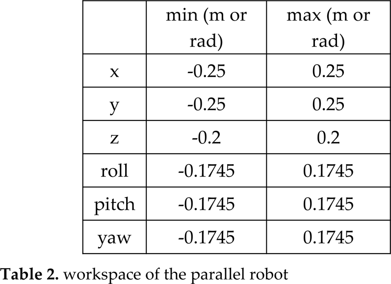
Table 3 gives the simulated calibration results. Note that the first row in the table corresponds to the initial conditions of the parameter set. The estimation error is calculated as the 2-norm of the difference between the actual deviations and the estimated deviations. To determine the resulting error improvement, the position error and the orientation error were computed as the root mean square error with random 100 poses in the workspace.
Calibration simulation results

The reduction of the parameter estimation error by itself is not the goal of the calibration. Ultimately, the resulting errors of the parallel robot should be reduced. Fig. 4 shows that by estimating the model parameters well, the overall accuracy of the parallel robot can be improved. This verifies that better parameter estimates will result in improved pose accuracy. Simply by updating the nominal parameter values stored in the controller with those estimated by the calibration, the resulting accuracy of the parallel robot can be increased. The plot shows good correlation between the parameter estimation error reduction percentage and the average workspace error reduction percentage.
Fig. 5 depicts the calibration of parameter set 3 with measurement corrupted by noise of 0.01mm. The parameter estimation error is reduced by 75%. Position error RMS was reduced from 1.6196 mm to 0.2753 mm, a reduction of 83%, and orientation error RMS was reduced from 0.1246 deg to 0.0162 deg, approximately 87%. Fig. 5 show representative pose errors before and after calibration.

The relation of identification error reduction percentage and pose error reduction percentage
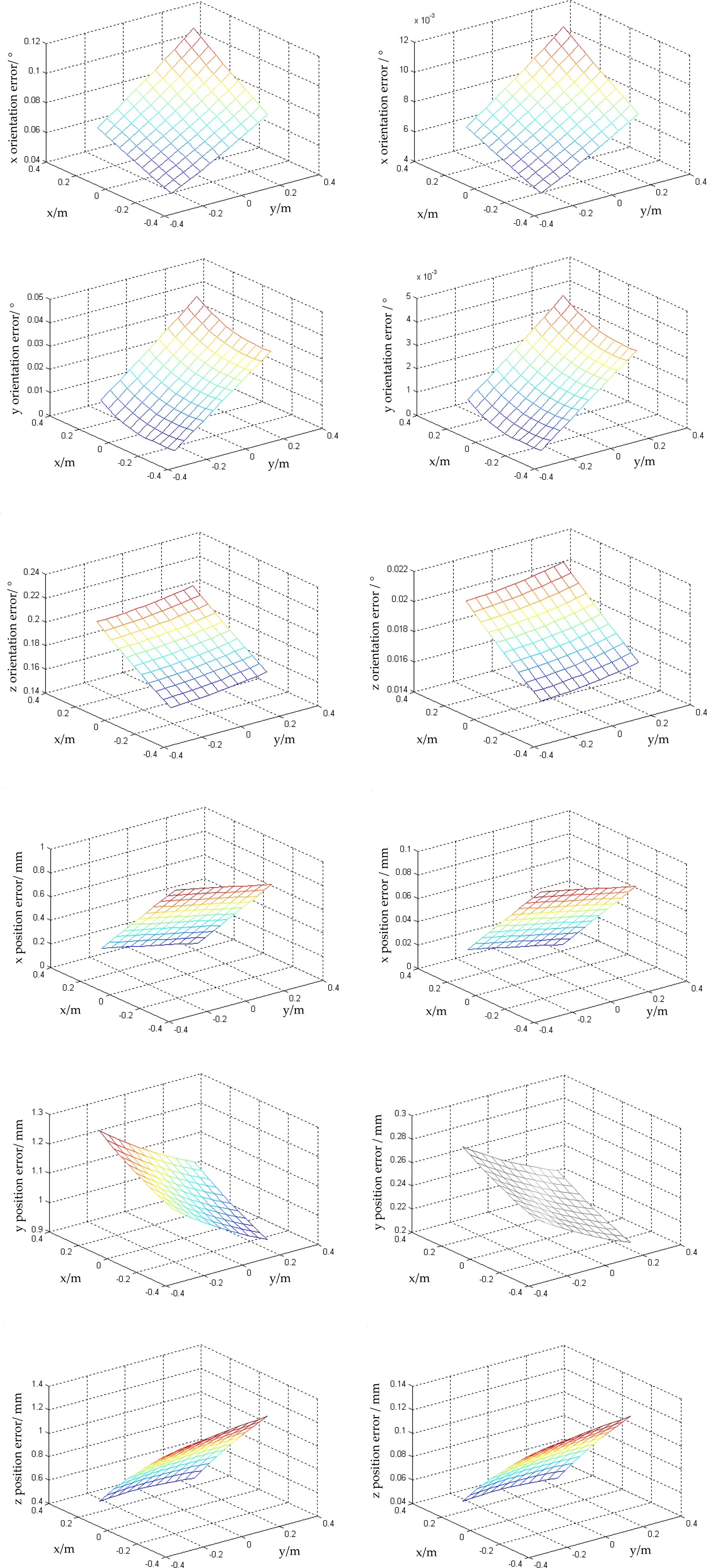
The comparison of pose error before and after calibration
For identification of the parameter errors of (18) a set of 50 measurement points was acquired, which is about uniformly distributed within the workspace. Within 5 iterations and 30 seconds calculation time the LS-method has identified the geometrical parameter set using the normal parameter set given in Table 1 as an initial guess.
The improvement in quantitative terms is given by the mean error and the standard deviation in Table 4.
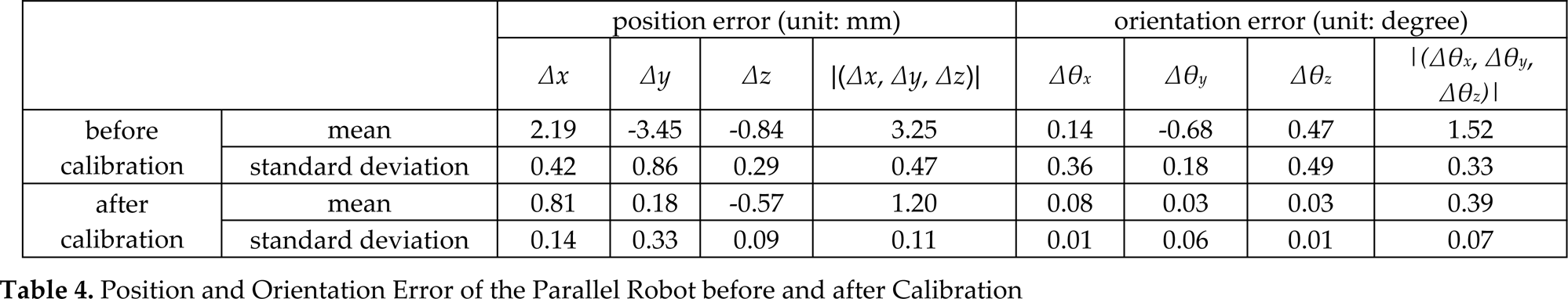
Position and Orientation Error of the Parallel Robot before and after Calibration
Position and Orientation Error of the Parallel Robot before and after Calibration
By calibration and full pose measurement the position error improved by a factor of 2.7 for the mean value and by a factor of 4.3 for the standard deviation. For the chosen size of the parallel robot this corresponds to an absolute quantitative improve of 3.3 to 1.2 millimetres for the mean value, whereas the standard deviation drops from 0.5 to 0.1 millimetres.
By calibration an accuracy improvement a factor 3.9 for the orientation error could be obtained on the mean value whereas the standard deviation decreases by a factor of 4.7. This corresponds to an absolute improvement of 1.5 to 0.3 degrees for the mean value and 0.33 to 0.07 degrees for the standard deviation.
A new kinematic calibration method for docking mechanism motion simulator was presented, using a coordinate measuring machine that made constraint conditions. Calibration equation was established to perform calibration with the proposed method. These measurement data were used to identify the parameters of the calibration equation resulting in an accuracy improvement of RMS (root mean squares errors) a factor of 2.7 for the position and a factor of 3.9 for the orientation.