
Abstract
In this article, a relative posture-based algorithm is proposed to solve the kinematic calibration problem of a 6-RSS parallel robot using the optical coordinate measurement machine system. In the research, the relative posture of robot is estimated using the detected pose with respect to the sensor frame through several reflectors which are fixed on the robot end-effector. Based on the relative posture, a calibration algorithm is proposed to determine the optimal error parameters of the robot kinematic model and external parameters introduced by the optical sensor. This method considers both the position and orientation variations and does not need the accurate location information of the detection sensor. The simulation results validate the superiority of the algorithm by comparing with the classic implicit calibration method. And the experimental results demonstrate that the proposal relative posture-based algorithm using optical coordinate measurement machine is an implementable and effective method for the parallel robot calibration.
Introduction
Parallel robots are closed-loop chain mechanisms whose end-effectors are actuated by a serial of independent computer-controlled serial chains linked to the bases. Parallel robots present some outstanding advantages in high force-to-weight ratio and better stiffness compared with serial manipulators. 1 Hence, parallel robots have been utilized increasingly in various applications such as flight simulators, manufacturing lines, and medical tools. 2
Normally, the control performance of uncalibrated parallel robots is significantly affected by the manufacturing and robot installation errors. Kinematic calibration is an effective method to remove the negative influence of these errors and to improve the accuracy of end-effector output in a robot control system. The calibration algorithms based on end-effector absolute posture are generally used to determine the optimal robot kinematic model. 3 This kind of algorithm needs accurate absolute location of the robot base frame in the sensor frame through a tedious pre-calibration procedure due to the lack of a well-defined and mechanically accessible base coordinate frame for the robot. 4 The location of the robot base frame with respect to the sensor frame is not needed in the relative posture (or posture variation) calibration. And based on the relative measurement, the constraint equations for deriving the entire considered kinematic parameters of the robot can be constructed for the calibration. Therefore, in this research, we focus on the kinematic model calibration based on robot relative posture with respect to the optical measurement system.
Although some researchers perform the calibration without using a robot kinematic model, 5 most kinematic calibration methods are kinematic model based. 6 –8 To identify the error parameters in the robot kinematic model, the model-based calibration is conducted in three steps: modeling, measurement, and calibration. 3
Based on the geometric analysis, a kinematic error model can be constructed by considering joint residual errors in kinematic parameters. Model-based kinematic calibration tries to rebuild a more accurate mapping between robot actuator outputs and the end-effector posture by determining those kinematic parameters. Precise parallel robot error model is built by denavit-hartenberg (D-H) method. 9 However, most researchers 10,11 choose a reduced model in the calibration considering that the contribution of joint manufacturing tolerances have a minor effect on the platform pose error. In other words, the manufacturing tolerances of the joints are neglectable. Nevertheless, the positional errors of the joint centers and the deviation of the active joint angles are the main reasons for the kinematic calibration.
The measurement sensors play an important role in the parallel robot calibration. It tries to collect enough redundant information for the calibration. The sensors usually fall into two categories: contact measurement and contactless measurement. For the contact measurement type sensors such as translation detector, 12 coordinate measurement machine (CMM), 13 inclinometer, 14 and double ball bar device, 15 they collect various posture information of the robot end-effector directly for the kinematic calibration. However, they have to meet the strict installation requirements. And the installation errors affect the contact measurement results in different directions and with different magnitudes when the measurand is moving. While for the contactless sensors like camera, 10 laser tracker, 16 and optical CMM, 17 it is more flexible to obtain the pose information of the end-effector. The contactless measurement can eliminate the sensor errors with the help of pre-calibration. Alternatively, the sensor location uncertainties can also be viewed as external parameters in terms of the kinematic error model, 10 which may increase the complexity of the error model and the computation cost. Ideally, the detection of relative posture (the variation of robot position and orientation) is independent of the sensors’ location. In this article, to realize a flexible installation and to avoid the tedious measurement procedure of the sensor location, an optical CMM sensor C-track 780 from Creaform Inc. (QC, Canada) is adopted to detect the relative pose of the 6-RSS parallel robot.
The classic implicit calibration method proposed in the study by Wampler et al. 18 utilizes the closure relation of the kinematic chains to form implicit constraint equations instead of pursuing the analytical solutions of the closure equations such as the inverse kinematic model. The implicit calibration method emphasizes that the errors are involved in the kinematic loop equations implicitly, rather than being explicit outputs of a conventional input–output formulation. 18 By removing the requirement to express errors explicitly, the formulation allows the analyst to concentrate on all sources of error. 18 And the implicit calibration method has been effectively applied to H4 mechanism10 and 6-UPS robot. 18 In implicit calibration method, the absolute posture of the end-effector with respect to the base frame should be obtained with the employment of the contactless sensor. In most applications, the kinematic calibration is known as an optimization problem with redundant nonlinear constraint equations. The methods such as classical nonlinear algorithms, 9,19 bundle adjustment approach, 20 and interval approach 21 are applied to solve it. The pose vector of end-effector with respect to the base frame is normally used to construct the objective function of the optimization problem based on 2-norm of vector. 10,18,22 Several robot posture configurations should be determined to collect enough information. The principles for the configuration selection of parallel robot calibration have been given in some literature, 23,24 in which the error parameter Jacobian matrix is utilized to minimize the influence of measurement noise in all candidate configurations. For the 6-RSS parallel robot, the effect of the posture selection should be analyzed for relative posture-based algorithm (RPBA).
Most researchers assume the sensor location is exactly known in the kinematic calibration experiment. 13,21 Hence, both the absolute and relative postures for the calibration algorithm can be easily determined. However, to derive the pose of the base frame of robots with respect to sensor frame is usually a tedious and time-consuming work due to the following reasons: (1) the manufacturers usually do not provide enough nominal dimension information of the robots and (2) the self-occlusion of the close structure of parallel robots results in measurement difficulties. If the sensor location is not known exactly, the existing absolute posture-based algorithms cannot be used for the kinematic calibration directly. Ideally, the relative posture information, that is, posture variation, can be utilized in the calibration to avoid the tedious measurement of the relationship between the base frame and the sensor frame. A relative position-based calibration algorithm12 is carried out for parallel robots, where a simple measurement system with three distance gauges and a ball mounted on the end-effector is employed to measure the relative position movement. However, the orientation accuracy cannot be evaluated. Since the gauges should be re-installed with strict rules in every candidate configuration, the installation errors cannot be removed during the calibration.
In this article, we have developed a relative posture-based calibration algorithm for a 6-RSS parallel robot built with a kinematic error model using an optical vision system and several target reflectors attached on the end-effector of the 6-RSS parallel robot. The detected feature points of the reflectors can be used to estimate the relative poses. The obtained relative postures are then used to construct an objective function, and the updating algorithm is determined by minimizing this objective function following the least square norm principle. Simulation has been carried out to prove the superiority of relative pose-based calibration method comparing with the implicit calibration method based on absolute posture measurement. The experimental tests show that the following advantages of the proposed algorithm comparing with the other relative position-based algorithm:12 both the position and orientation variations can be utilized and no accurate location information for the detection sensor is needed. Both simulation and experimental results demonstrate that the proposal RPBA using optical CMM is an implementable and effective method for the parallel robot calibration.
The article is organized as follows. The kinematic error model and the visual detection system are introduced in the section “Kinematic robot model and pose estimation.” The section “Calibration algorithm based on optical CMM” presents the classic implicit calibration method and the RPBA based on the optical CMM. In the section “Simulation case study,” simulation results on optimal actuator stroke and calibration are presented. Finally, experimental case studies for the 6-RSS parallel robot kinematic calibration are given in the section “Experimental verification,” and conclusion is drawn in the last section.
Kinematic robot model and pose estimation
In this section, the kinematic robot error model is built based on the 6-RSS kinematic analysis. And the optical CMM system for the robot posture detection is introduced.
Kinematic modeling and error analysis
The literature survey shows that the research on the actuator-coplanar 6-RSS parallel robot kinematic modeling is very rare. In this research, the kinematic model of the parallel robot is built based on the geometrical analysis. Figure 1 shows the 6-RSS parallel robot with six coplanar rotary actuators. There is only one actuator in each parallel robot chain, and the kinematic model can be described by six equations given as follows


Structure of the 6-RSS parallel robot.
For a complete error modeling of 6-UPS robots, 132 geometric error parameters are identified by Masory et al. 9 The geometric parameters can be reduced to 42 assuming that a good manufacturing quality is applied to the joints. The reduced error model is introduced in Wang’s result, 26 which shows that the position accuracy of Stewart platform is insensitive to the joint errors. The reduced kinematic error model is considered in this article. Notice that the joint values θi are measured by built-in potentiometers in the 6-RSS parallel robot. The linear relationship

between the angle offset Δθi, sensor outputs κi, and angle conversion coefficients ηi can be used to compute θi.
27
Based on the kinematic analysis, the considered parameters include initial terminal coordinate errors
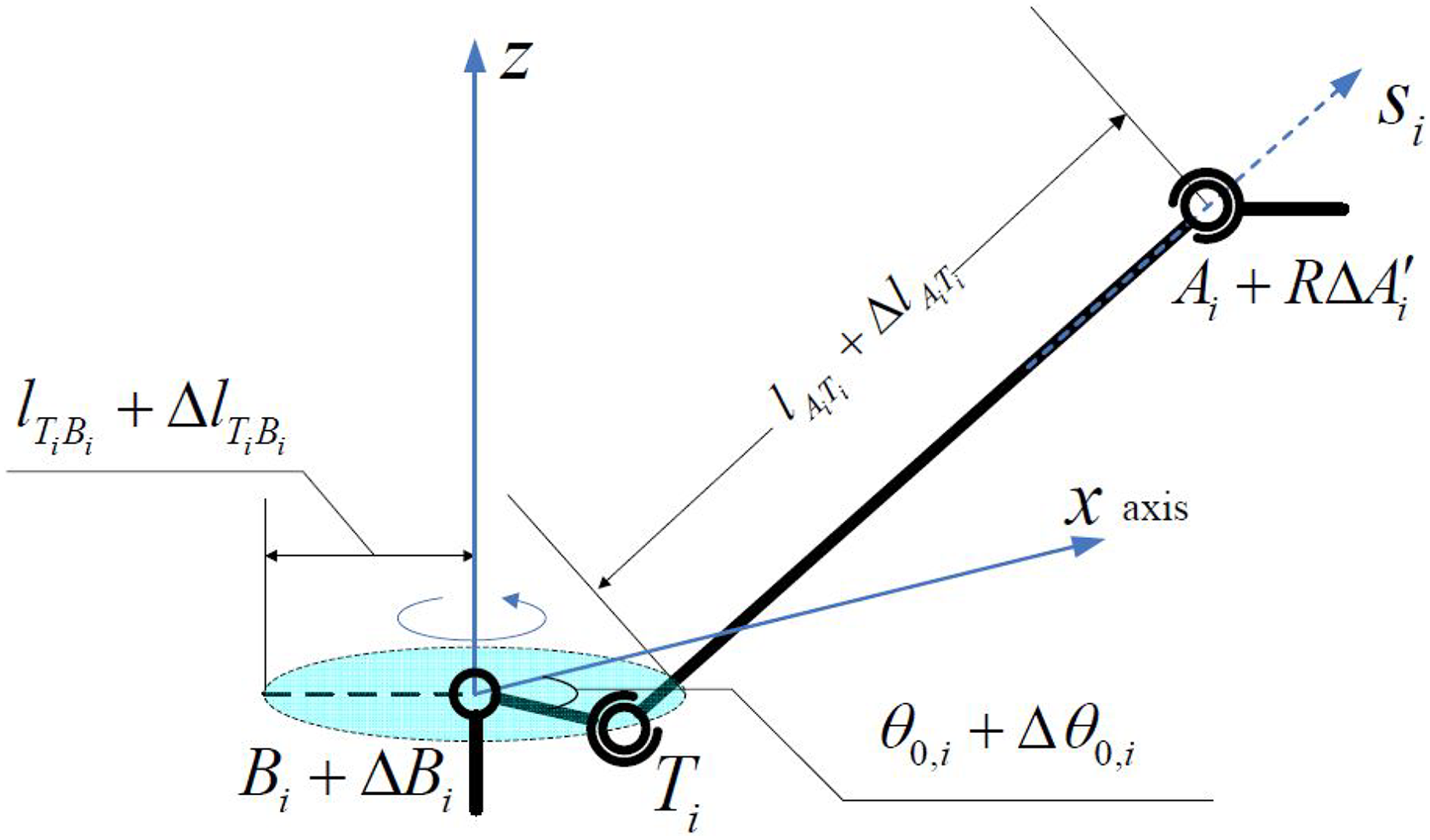
Error parameters considered in the model.
The kinematic error model is then given as follows

Pose estimation using optical CMM
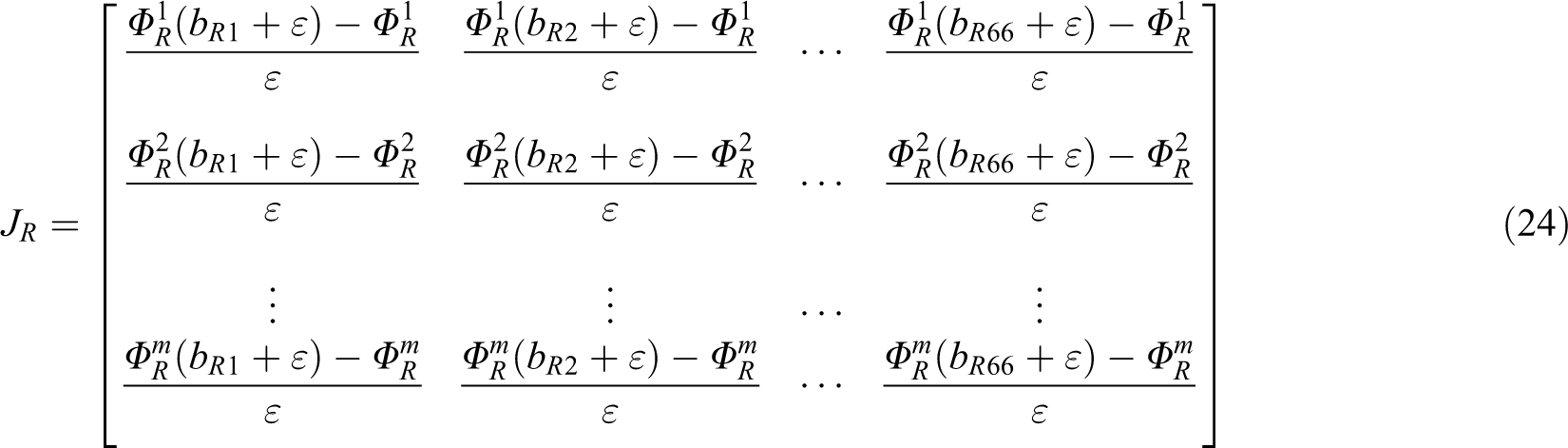
The kinematic calibration can be converted to an optimization problem with redundant nonlinear constraint equations. As shown in Figure 3, a dual-camera optical CMM C-track 780 is employed to estimate the pose of end-effector as redundant data for the optimization problem in this research. The pose estimation principle of binocular vision is presented in this subsection. n reflectors (n > 3) placed on the robot are chosen as feature points to form the target frame Σt. Given a group of noncollinear feature points


where

where min(⋅) represents the minimization function subject to the constraint

The calibration system of 6-RSS parallel robot.
After the position information of all the feature points on the end-effector is prepared, the pose estimation of the end-effector can be developed. Suppose n feature points on the rigid end-effector are fixed and known from the definition of the tool frame Σt, whose homogeneous coordinates are denoted as

where
Calibration algorithm based on optical CMM
In this section, we start with the classical implicit calibration method based on optical CMM for parallel robots. Since optical CMM device is involved, external parameters that describe the relationships between base frame and device frame, end-effector frame and target frame should be considered during the implementation of this method. The kinematic parameter
Implicit calibration based on optical CMM
The implicit kinematic model that depicts the closed structure of parallel robots is commonly employed in parallel robots kinematic calibration, since it can avoid solving inverse kinematics and forward kinematics. 18 The choice of implicit kinematic model can be various. Normally, it should be equations that reflect the relationships between joint values, kinematic parameters, and the pose of end-effector. For the 6-RSS parallel robot, the constraint equations ΦI of implicit kinematic model for calibration can be derived from equation (3)

where ΦIi is the ith element of ΦI. Then the kinematic calibration can be derived by solving an optimization problem with the measurement of joint values

However, due to the employment of an external optical device,

where
The 12 parameters representing

Then the updating formula for

where

In some researches,
33,34
the vector
To achieve the better results in solving the nonlinear optimization problem, accurate initial guesses of
RPBA based on optical CMM
Here we propose RPBA in which the posture variation of parallel robot end-effector can be used to eliminate the influence of external parameters. The transformation matrix Ml expressing the relative pose between the lth end-effector configuration

The forward kinematic of the 6-RSS parallel robot can be represented by
If we define the bijective mapping from homogeneous transformation matrix to the posture as χ = L(M), combining equations (14) and (15), the constraint function ΦR for calibration can be derived as the following equations

where

where

where

As we can see from equation (17), the parameters representing
Constraints determination for robot configuration selection
The robot configurations used in the kinematic calibration, or named as candidate configurations, will affect the performance of calibration results.
24
In this section, we first introduce the constraints for the robot configurations selection based on kinematic analysis results on workspace and singularity.
25
According to the updating formula (12), two constraints for the candidate configuration selection are listed as follows: They should be selected in a workspace where any robot configuration corresponds to unique actuator outputs. The kinematic mapping f is totally singularity-free so that all elements in JT exist.
The first constraint, known as homomorphism constraint, 35 ensures that the forward and the inverse kinematic calculation will converge to the right value during the calibration. Based on the implicit function theorem, the existence of all elements in JT requires for the singularity-free of inverse kinematic mapping. As the Euler angles are limited in [−π, π], the mapping h is a homomorphism which ensures that the forward and the inverse kinematic mapping have the same kind of geometric characteristic. Then for the second constraint, we require a singularity-free f. The singularity analysis is normally based on the Jacobian matrix of the kinematic mapping. 36 As shown in Figure 1, when the velocity projection of Ai and Ti on Ai Ti equals each other, we have the following equation

where i = 1,…,6, si is the velocity unit vector for Ai Ti, swi is the velocity unit vector for terminal Ti, and
where


As shown in the study by Park and Kim,
36
if If If If
Singularity-free is not a sufficient condition for the uniqueness of forward kinematic solution in parallel robots. 37 The second constraint requires for a workspace in which f is a bijective mapping. The conclusion in our previous study 35 is directly used: kinematic mapping f is a homeomorphism if the following equation holds:

where σi and λi are the ith singular value and the eigenvalue of
Identifiability and observability index
Since external parameters are involved in both implicit calibration and relative calibration, we first need to check the identifiability of external parameters and kinematic parameters to see if there is linear dependency between those parameters. According to equations (13) and (19), if any parameter did not lie in the kernel of the regressor JI and JR, the parameter to be calibrated cannot be updated in each iteration, which means the parameter is non-identifiable. Therefore, the full rank of JI and JR should be guaranteed.
In addition to checking the identifiability of kinematic and external parameters, the observability should also be considered to minimize the estimation errors by selecting an optimal set of calibration candidate configurations. In this research, the observability index proposed in the study by Borm and Meng,
38
which emphasizes the volume of a hyper-ellipsoid whose directions are represented by the singular values denoted by

where m is the number of calibration candidate configurations and w is the number of error parameters.
Simulation case study
In this section, simulations are based on the geometry of 6-RSS parallel robot depicted in Figure 1 and the setup is shown in Figure 3. We firstly determine the proper actuator strokes for RPBA. And the optimal set of candidate configurations is determined for both implicit and relative calibration method. Then the calibration simulation comparison of two calibration methods is implemented to show the superiority of RPBA.
The actuator stroke for calibration posture determination
Compared with the end-effector postures, it is more convenient to describe the robot configuration by the actuator joints value. Hence, the results in this subsection are all determined in the actuator parameter space. Besides, the kinematic calculation is based on ideal kinematic model. Two kinds of parallel robot configurations should be detected for the kinematic calibration: the initial configuration and the candidate configurations. The optimal initial actuator angles should be initial angles singularity I-free condition singularity II-free condition homomorphism condition equation (22).
The optimization procedure is shown in Figure 4. Assuming the initial angle is at the zero degree axis of the polar coordinate, we try to determine the upper and lower bounds of the actuator stroke. In the first 40th step, the two bounds are modified together. After the 40th step, the two bounds are modified separately. Finally, the robot configurations should be selected in the actuator stroke

The determination of proper actuator stroke.

Bijective verification through the boundaries.
Optimal set of calibration configurations selection simulation
In this subsection, we check the identifiability and the observability of the kinematic parameters for both implicit calibration and relative calibration. According to the section “Identifiability and observability index,” the identifiability of
where
The searching method of the optimal set of calibration configurations proposed by Nubiola et al. is used in this article to maximize the index O. 39 For both calibration methods, the numerical algorithm starts with a candidate set of 13 random configurations selected from the determined actuator stroke in the previous subsection. At each iteration, one configuration chosen from 5000 random configurations in the proper actuator stroke is added to the candidate group. If the index increases, we keep this configuration in the candidate group and remove any configuration which decreases the index of the set of configurations remaining, otherwise we remove this configuration and go to the next iteration.
For implicit calibration method, the algorithm is saturated after 618 iterations with the resultant index 0.0031 which cannot be improved. And for relative calibration method, the maximum index goes to 0.0322 with 572 iterations. The optimal sets for implicit and relative method contain 34 and 22 configurations, respectively.
Calibration simulation
In this subsection, the simulation is carried out on the case study of the posture variation of a 6-RSS parallel robot detected by the optical CMM system. The detection noise in the simulation is determined based on the experimental analysis.
As introduced in the previous section, the reflectors attached on the end-effector can be used as the feature points for the posture
The standard deviations of the noise distribution.
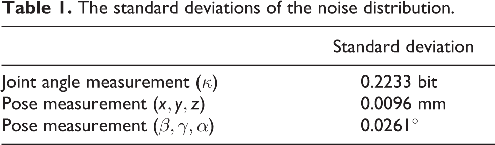
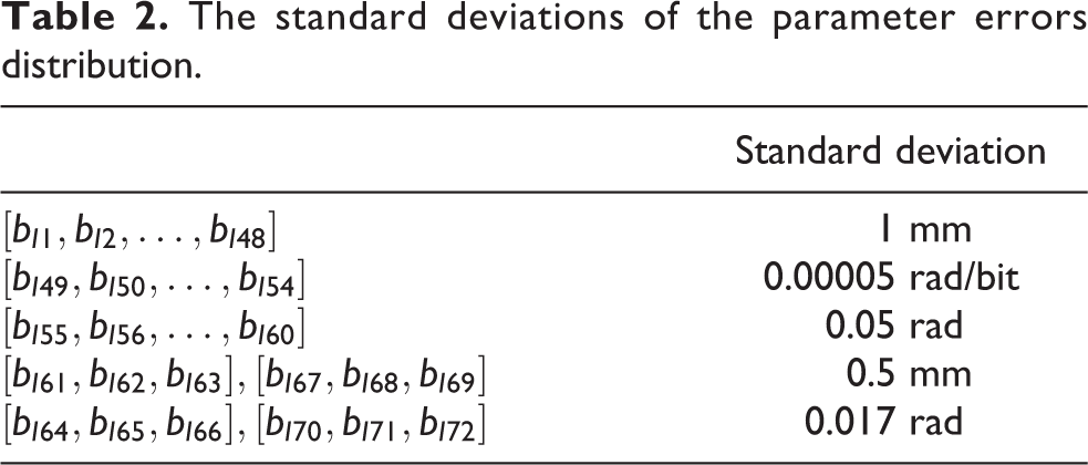
In the calibration simulation, we randomly generated a group of parameter errors
The standard deviations of the parameter errors distribution.
In the simulation, the procedure of implementing the implicit calibration method is given as follows:
Load the initial parameters Generate a group of parameter errors with normal distributions of certain standard deviations as mentioned. By adding the errors to the initial parameters, we can obtain the real kinematic parameters Load the optimal set of 34 configurations derived from previous subsection for the implicit calibration method. Through equation (2), we convert the optimal set expression in the actuator domain into joint readings. Then we derive the joint measurement The measurements of the poses The updating formula equation (11) is used to determine the optimal error parameters
After 11 iterations, the calibrated error parameters
The error norms between nominal and calibrated values—normal for implicit calibration method.

For the RPBA simulation, the procedure is similar to that of the implicit calibration as follows: Load the initial parameters Extract the subset Load the optimal set of 22 configurations derived and derive the joint measurement The measurements of the relative poses Ml are derived from the forward kinematics and equation (15), employing the real kinematic parameters The updating formula equation (17) is used to determine the optimal error parameters
After four iterations, the calibrated error parameters
The error norms between nominal and calibrated values—normal for RPBA.

RPBA: relative posture-based algorithm
Since the external parameters in Without loss of generality, a trajectory with 100 random relative configurations Load the initial parameters Derive the trajectory expression in actuator domain Input the deriving
Converting
The results are shown in Figure 6 and Table 5. The results show that the RPBA can improve the relative accuracy of the parallel robot in both translational and angular portions compared with the implicit calibration method. The implicit calibration results lead to a considerable improvement on the angular portion of the relative accuracy, but only slight improvement is gained in terms of the translational accuracy. The reason is that there are six more external parameters used in the implicit method. However, the relative accuracy is largely dependent on the internal parameters. The RPBA can improve the relative accuracy significantly in all directions of the relative pose along the given trajectory. Therefore, a conclusion can be drawn that considering the relative accuracy, the parallel robot can fulfill more accurate positioning tasks based on the proposed RPBA than those based on the implicit method.

The simulation results of relative pose errors derived from implicit calibration, relative calibration, and uncalibration: (a) along x direction, (b) along y direction, (c) along z direction, (d) around α-axis, (e) around β-axis, (f) around γ-axis.
The RMS of the relative pose errors in simulation.

RMS: root mean square.
Experimental verification
The experiment is supported by QUARC 2.1 platform (Quanser Inc., ON, Canada) which connects to the KEB-COMBIVERT motor servo through the interface card Sensory 626. The 6-RSS parallel robot is provided by Servo & Simulations Inc. (FL, USA) and two Quanser cards are used to communicate with six individual servers that deal with the dynamic control of actuators. One computer communicated with the optical CMM sensor C-Track 780 is in charge of image processing, and other computer deals with the control of the parallel robot. Serial port is used to transfer data between two computers. The experimental setup is shown in Figure 7.
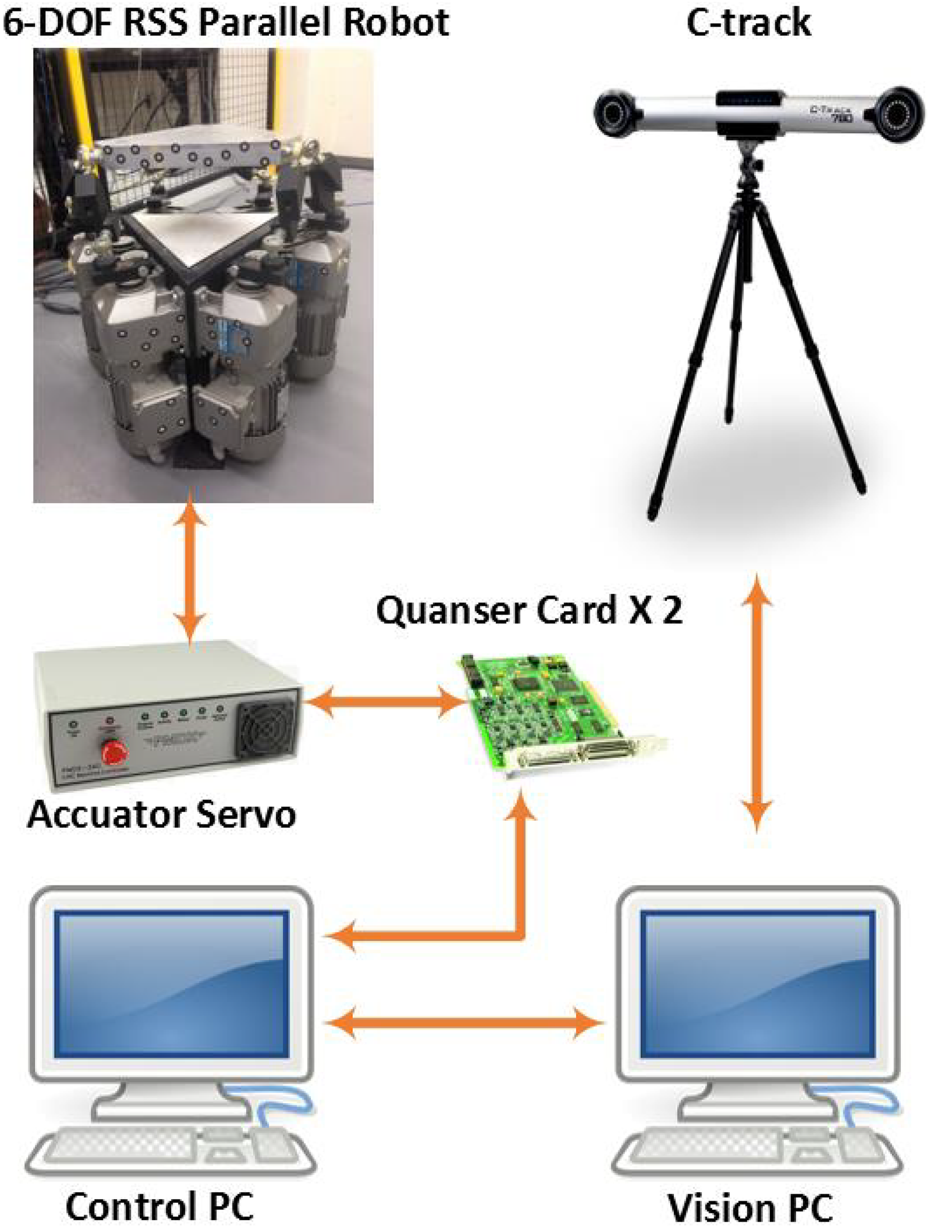
Experimental setup system.
As we can see, the base frame of the parallel robot is mechanical unaccessible and unobservable for the optical sensor. Since the manufacturer does not provide accurate geometric information, it is nontrivial and time-consuming to obtain a good initial guess of
As shown in Figure 8, the reflectors are attached on the well-machined surface of the moving platform. Σe is designed on the symmetric center of the moving platform. At least three noncollinear points on each plane of plane A, plane B, and plane C are employed to build up equations of planes based on Cramer’s rule. Then the intersection lines and points of three planes can be used to define the x direction of Σe, and the y direction is aligned with the norm of plane A. The original point of Σe is derived from the intersection point of l1 and l2. Then the derived Σe in the optical CMM sensor frame is directly used as the target frame. Therefore, the initial parameter of

Measurement of
For the relative calibration, the optimal set of 22 configurations derived from the previous section is selected as candidate configurations. And the actuator values are set as
To verify the calibration results, a trajectory with 100 random relative configurations

The experiment result of relative pose errors derived from calibrated model and uncalibrated model: (a) along the x direction; (b) along the y direction; (c) along the z direction; (d) around α-axis; (e) around β-axis; (f) around γ-axis.
The RMS of the relative pose errors in experiment.

RMS: root mean square.
Conclusion
In this article, a relative posture-based kinematic calibration method is proposed for a 6-RSS parallel robot using the optical CMM system. The developed calibration algorithm can improve the positioning performance with respect to its initial configuration. In this algorithm, the base frame pose with respect to the sensor frame is not needed, which leads to an effective relative calibration method for the parallel robot. Since the forward kinematic model is used in the relative pose-based calibration, the optimal actuator strokes of the parallel robot are derived to ensure the homeomorphism mapping of the forward kinematic model. The simulation results show the relative pose-based calibration algorithm successfully improves the relative accuracy of the parallel robot. The comparison with the implicit calibration demonstrates that the RPBA can deliver a more satisfactory relative accuracy. The experimental tests on an arbitrary trajectory with 100 configurations further show that the proposed RPBA has improved the relative accuracy of the selected trajectories in 3-D space effectively. The developed calibration algorithm can be applied to other types of parallel and serial robots. And the calibration results would be used in a 6-RSS parallel robot visual servoing system in the future.
Footnotes
Declaration of conflicting interests
The author(s) declared no potential conflicts of interest with respect to the research, authorship, and/or publication of this article.
Funding
The author(s) received no financial support for the research, authorship, and/or publication of this article.