
Abstract
To fulfill the microassembly work successfully, an omnidirectional mobile microrobot is presented. To finish the micron size task, the positioning precision of the robot is highly important. But some unpredictable factors, especially the slip effect in wheel, would affect the precision of the robot and cause unwanted deviation. To limit the deviation and optimize the positioning performance of the robot, a new wheel structure is designed. The design of the new wheel is based on magnetic principle while considering the potential problems brought by the magnetic units. With nonlinear dynamic analysis with slip of the microrobot and simulations based on it, the slippage effect is shown to be limited a lot with the application of new wheel structure. And following experiments are executed to verify the optimization brought by the magnetic wheel structure.
Keywords
Introduction
With the development of MEMS and micro-technology, assembly in micro scale catches more and more attentions. During such process, micro-components created by MEMS will be sent to assembly factory to be assembled there, thus to form a complete structure.
However, assembly in micro and macro size is different (Brussel & Peirs, 1995; Popa & Stephanou, 2004). Firstly, the requirement of precision in micro world is much higher compared to that of macro world, and micron precision is often required (Popa & Stephanou, 2004), thus the sensors in micro world should be extremely small and sensitive (Shuang et al., 2008). And secondly, in micro world, the detailed surface-related forces which can be ignored in macro world play a great role in motion of the object. Thus the mechanics of manipulation in micro world would be somehow unpredictable and macro assembly systems are hard to fulfill the task in micro scale (Dario et al., 1998). With above consideration, microrobot would be an efficient way to complete microassembly task, for it can fulfill the task with high precision, high efficiency and low energy cost.
The omnidirectional mobile robot (Li, J. et al., 2007) reported before is designed to accomplish such microassembly work. With the assigned task, the microrobot would move to assembly area autonomously and accurately, so as to accomplish the work. Therefore, the positioning precision of the robot appears to be very important. However, during the procedure, many outer factors could affect the positioning precision. Being one of them, slip in wheel is the constant factor which could bring unwanted deviation and affect the positioning precision (Balakrishna & Ghosal, 1995; Chung & Velinsky, 1999; Williams et al., 2002; Lin et al., 2007).
To prevent the slippage, using sensor to detect slip and avoiding it is an efficient way (Mazid & Ali, 2008; Ojeda et al., 2006; Ward & Iagnemma, 2007), but it would be hard to apply an additional sensitive sensor on this micro size robot. Robot learning (Angelova et al., 2007; Lin et al., 2007) and other algorithm also could help to eliminate the slip effect and optimize the precision of robot, however, these algorithms would take more time to adjust the robot to a better work status, i.e. the efficiency would be reduced.
In this paper, a new magnetic wheel structure for the microrobot is presented to limit slippage effect and improve the dynamic performance. This new wheel is based on magnetic principle and it is combined with the actuator, thus to cause less complexity. And ANSOFT simulations are executed to determine the parameters of it. With this new wheel structure, analysis and simulations based on a nonlinear dynamic model with slip prove the improvement brought by it. The following experiment also verifies such optimization.
The paper is organized as follows. Section 2 introduces the architecture of the optimized tri-wheeled mobile microrobot, including the mechanical structure and the actuator. Section 3 designs the new magnetic wheel structure. Section 4 establishes a nonlinear dynamic model with slip and executes simulations based on it. Section 5 presents the experiment to verify the optimization brought by the new wheel structure, followed by conclusion.
Architecture of the mobile microrobot
Tri-wheeled omnidirectional structure (Li, J. et al., 2007)
The size of the tri-wheeled mobile micro-robot is 9 mmx9 mmx6 mm as shown in Fig. 1 and it weighs 3.2g. The robot is composed of three wheels mutually geared through three big micro-gears and one small micro-gear (the transmission ratio is 3:1), and one piezoelectric micro-gripper, as shown in Fig. 1(a). Four 3mm electromagnetic micro-motors are applied to actuate the robot (three mounted on the wheels for translational movement and one settled in the middle of the robot chassis for turning movement). The front wheel is connected to the chassis through a single-side cantilever, and other two wheels are supported by double-side cantilevers.

The CAD model of the microrobot.
The middle micromotor drives the rotation of the small micro-gear, and the steering power will be amplified and transmitted to wheels through the gear set. Connected by the gear set, during the turning movement, the three wheels can steer synchronously in the same angle and the precision of rotation can be improved for the 3:1 transmission ratio. This structure also can make translational movement and turning movement separately, thus to achieve the omnidirectonal movement.
The micromotor equipped on the wheeled robot is axial flux original electromagnetic micro-motor designed by genetic algorithm and fabricated with non-silicon MEMS Process (Li, Z. et al., 2000). It has six coils on one stator and eight magnetic poles on the rotor as shown in Fig. 2.

The structure of the micromotor.
When using PWM-based vector-synthesize approach (PBVSA) (Li, Z. et al., 2007), the precision of the micromotor can reach 2.5°/step. With the 4mm-diameter-wheel, the precision of translational movement is 0.087mm/step, and the turning precision can reach 0.83°/step with the 3:1 transmission gear set.
As reported in many research works (Balakrishna & Ghosal, 1995; Chung & Velinsky, 1999; Williams et al., 2002), slip is a primary factor to affect the positioning precision for robot, and it is hardly to be eliminated (Piedb & Hurteau, 2000). However, if this effect can be limited in some extent, the positioning performance of the microrobot also could be improved a lot. In this section, an optimized wheel structure is presented to limit such deviation and improve the dynamic performance for the wheeled microrobot.
The slip effect mainly exists in acceleration or deceleration stages during the move of robot (Balakrishna & Ghosal, 1995; Williams et al., 2002). As the friction force is directly related to acceleration or deceleration of wheeled robot, with the same mass, the larger the friction force is, the larger the acceleration or deceleration is, and the less time it would take the robot to catch up the wheel speed, as to pass the slip stage.
One way to increase the friction force is to use a tire with higher friction coefficient. But as the work platform has a smooth surface, it is difficult to fabricate such tires meeting the requirement. Another way is to change the supporting force N. As the friction force has direct proportion with N, and the platform for the assembly work is made of ferromagnetic material, magnet could be used to increase N with less increment in mass, thus to increase the friction force and limit the slippage. With above consideration, a novel magnetic microwheel structure is designed to replace the normal wheel to limit the slippage. To provide magnetic force, permanent magnet is used, and two ferromagnetic pieces are sticked on both side of the magnetic wheel to let the magnetic flux go through the platform, thus to increase the attraction force, as shown in Fig. 3. And as this wheel is applied on the micromotor directly without additional axles, this optimization would not make the structure too complex and bring too much increment in mass.

New wheel structure. (a) Perspective graph in side view. (b) Cross-section in front view.
However, the magnetic units applied on the wheel may interact with each other or cause additional force that would affect the move of microrobot. Thus, before determining parameters of the new wheel, other two factors should be taken into consideration. Magnetic force must satisfy the conditions as follow; otherwise the motor would not be capable to drive the wheel in translational and steering move.
To actuate the robot in translational move, the driving moment given by the micromotor should be larger than the resultant resisting moment as shown in Fig. 4. Thus the moment applied on wheel and the magnetic force should obey the rule as follow,


The side view of the microwheel.
where M d is the driving moment given by the micromotor, M b is the resisting moment given by the axle, r z is the radius of the axle, μ z is the friction coefficient between the axle and the wheel, and M f is the friction moment given by the friction force on point G, F mp is the attraction force between the magnetic wheel and the ferromagnetic platform.
Then the range of F
mp
can be concluded as,

Because magnetic wheels are applied on all three wheels of the microrobot, there exists magnetic force among each other as shown in Fig. 5, and these interactions might cause some problems for turning motion. With the 3:1 gear ratio for rotation, the driving moment for turning is 3M
d
, then the resultant torque given by magnetic force in the same direction should be less than 3M
d
, otherwise the robot would be unable to steer.

where T F m is the resultant torque given by magnetic force in steering direction.

The interaction between the three magnetic units.
For the relatively high coercivity, SmCo is chosen as the magnetic unit on the new wheel, and the ferromagnetic piece is made of FeNi alloy due to its easy machinability and high magnetic permeability. As the rotor of micromotor has 1.65mm radius, and to remain the postioning precision of microrobot, the magnetic unit and ferromagnetic piece are both designed as ring structure as shown in Fig. 3, and the outer radius is 2mm with 1.65mm inner radius. To provide adequate path for magnetic flux, the FeNi piece is 0.8mm in thickness. To determine the size of the magnetic unit and satisfy the rules mentioned above, some ANSOFT simulations are executed as shown in Fig. 6.
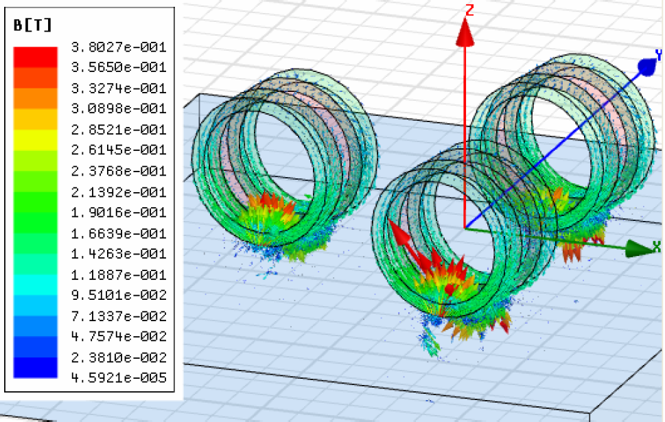
ANSOFT simulation for magnetic wheel.
The magnetic attraction and maximum interaction among wheels with different thickness of magnet are shown in Fig. 7. In the figure of magnetic attraction, the curve's steepness decreases with increase of thickness. To ensure enough magnetic attraction and remain less increment in mass, the thickness of magnet is chosen as 1mm. In this condition, the mass of microrobot would increase to 3.2g. With the maximal driving moment M d_Max = 10 μN·m, and r z = 0.3mm, μ z = 0.18, μ S = 0.21, r = 2mm, F mp should be less than 1.064times10−2 N from Equ. 2. By ANSOFT simulation, the magnetic attraction among wheels with 1mm thickness magnet is 9.7times10−3 N which meets the requirement in Equ 2. Meanwhile, the maximum interaction is just 0.1875 μN which affects the steering move less. With the above analysis, the new wheel and its size is shown in Fig. 8.

ANSOFT simulation results.

Structure and assembly of the magnetic wheel.
Modeling of wheeled mobile microrobot is generally described as nonholonomic dynamical system, in which the wheels are assumed to roll without slippage. However, the slippage actually exists in the process of moving and it does affect the positioning performance of the wheeled mobile robots and cause navigational error. In this section, the dynamic model of the wheeled mobile microrobot is established based on the friction model. And following simulations and analysis will compare the positioning precision with normal wheel to that with magnetic wheel respectively.
Model of slipping velocity
Since all the actions of the microrobot are performed on a plane in general condition, a planar coordinate system is used to analyze the dynamic model of the robot as shown in Fig. 9. The inertial frame is {O}, and the robot frame or the moving frame settled on the center of the chassis of robot is {M}. The three wheels are symmetrically placed, aligned by 120° from each other, and the center of each wheel is fixed with respect to the robot frame. The distances from the center of each wheel to the origin of {M} are all defined as L. The orientation of the robot with respect to the inertial frame is given by angle φ. The unit vector
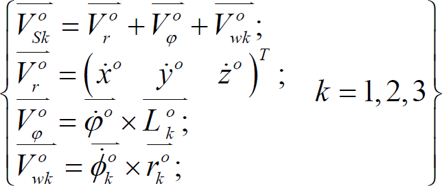

The model of microrobot. (a) Top view of the microrobot. (b) One wheel model.
where
When
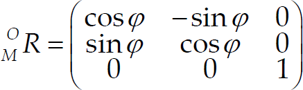
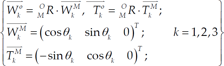
Using an orthonormal rotation matrix
O
M
R, vectors in robot frame can be converted into inertial frame as follow,
Friction plays an important role in robot manipulator simulation, also it is a prime factor affecting the slip effect and positioning performance of the wheeled robot. One extensively used model is the classical Coulomb model (Piedb & Hurteau, 2000), but its discontinuity at zero may cause instability in simulation. Thus, in this research, another simplified continuous model is used for the coefficient of friction,

where V
S
is the slipping velocity, μ is the static friction coefficient, p is constant for amplifying, respectively. Assuming that the weight of the robot is distributed averagely on each wheel, the friction force on point G can be denoted as,

where μ
L
(V
SLk
) and μ
T
(V
STk
) is the simplified function for friction coefficient in longitudinal and transverse direction versus slipping velocity respectively. with normal wheel:

The microwheels of the robot are all set as active and each is connected to one micromotor. And the moments applied on the wheel are shown in Fig. 4, then the dynamic function of kth wheel can be given as,

As illustrated in Fig. 10 and mentioned in section 2, wheel 1 is supported by a single-side cantilever while wheel 2 and wheel 3 are connected with the gear through double-side cantilevers. The asymmetry of single-side cantilever raises an additional torque T
a
that will cause unwanted rotation during the translational move,

where d1 is the distance between the center of the microwheel and the cantilever.

The asymmetry of the supporting structure.
Within the above analysis and rigid body dynamics, the dynamic equations can be concluded as,

where
Based on the above model, some simulations are executed in this section. To observe the dynamic performance clearly, no additional control method is applied on the microrobot, and the control maneuver is: calculating the θ and time t according to the goal location, initial location and stable wheel angle velocity, then let the microrobot move in θ direction for t s. The stable velocity of the micro-robot is set as 4.4 rad/s and φ is initialized as 0°. The other dynamic parameters are given as follow, m = 2.8g (3.2g with magnetic wheel), μ L = μ T = 0.21, L = 4.15mm, r = 2mm, d = 1mm, F mp = 9.7times10−3 N.
With the above parameters, the trajectory of initial simulation is set from location (0 0 0) T to (8.8 0 0) T (mm) which means the moving time is 1s and the direction angle θ = 0°. The simulation results with normal wheel and magnetic wheel are shown in Fig. 11 and Fig. 12 respectively. Fig. 11(a) and Fig. 12(a) show the lognitudinal and transverse slipping speed of the three wheels. It can be observed that slippage mainly exists in the acceleration stage and deceleration stage, and lasts longer during deceleration. And with the new wheel structure, the slip effect is limited in both lognitudinal and transverse direction for it exists for much less time. In Fig. 11(b) and Fig. 12(b), the simulation route and the ideal route of the microrobot are both shown. Using normal wheel, the stop location of the simulation has 0.1551mm drift from the ideal goal location while the deviation is only 0.076mm with the new magnetic wheel. In Fig. 13, a compare of the deviation with magnetic wheel and normal wheel respectively in 8.8mm moving distance and different direction is shown. The deviation with magnetic wheel is only about 0.07643mm with different direction while the drift reaches 0.1551mm which is two times of the former deviation. This simulation could represent almost all the situations in translational move and prove the improvement brought by the new wheel structure.

Route simulation with normal wheel. (a) Lognitudinal and transverse slipping speed versus time. (b) The simulation route compared to the ideal route in the distance of 8.8mm.

Route simulation with magnetic wheel. (a) lognitudinal and transverse slipping speed versus time. (b) the simulation route compared to the ideal route.

Compare of the deviation with magnetic wheel and normal wheel respectively in 8.8mm moving distance.
To verify the new wheel structure, an experiment based on new wheel structure is performed. In this experiment, several targets on platform are set, and the microrobot with normal wheel and new wheel is manipulated to move to the targets one by one respectively as shown in Fig. 14(a). The optimized microrobot with magnetic wheels is shown in Fig. 14(b) with a ruler. In this experiment, inspection camera set above the platform is used to capture the position of the robot and measure the deviation as shown in Fig. 14(c).

Experiment for multiple targets. (a) Experiment design. (b) The optimized microrobot. (c) The experiment platform and cameras.
The experiment result is shown in Fig. 15, from the chart, it can be clearly found that with the new wheel structure, the microrobot achieves a higher positioning precision with compare to the normal wheel structure. Therefore, this new wheel structure can limit the deviation caused by slip, thus to improve the positioning precision.
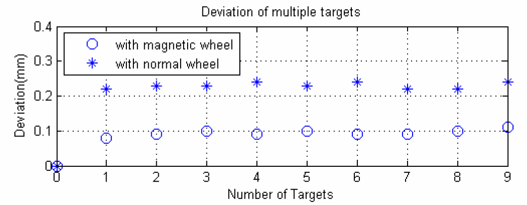
Experiment result.
In this paper, a new wheel structure is designed for an omnidirectional mobile microrobot to limit the slip effect in wheel and optimize the positioning performance. By analysis of magetic interaction and requirement, the new wheel structure is presented with consideration of the disadvantage brought by the magnetic units. Applying with the new wheel, with analysis and simulations based on a nonlinear dynamic model with slip, compare between normal wheel and magnetic wheel shows the precision increases about two times with the new wheel structure which means it successfully helps the microrobot decrease the deviation and improve the efficiency. The following experiment also compares the two wheel structures and proves the optimization brought by the new wheel.
In this paper, though the deviation of the microrobot decreases a lot while using the new wheel structure, this structure can only used on ferromagnetic platform. In order to widen the application of the microrobot and remain the precision, new motion structure and new control method are under research. And as the magnetic wheel of the robot could provide attraction force on the surface, another research on climbing move of the microrobot is in process as well.
Footnotes
7. Acknowledgements
This work is supported by Hi-Tech Research and Development Program (“863”Program) of China (No. 2007AA04Z340) and the Specialized Research Fund for the Doctoral Program of Higher Education of China (No.20060248057).