
Abstract
Closed-loop inverse kinematics (CLIK) algorithm mostly resolves the redundancy at the velocity level. In this paper we extend the CLIK algorithm to the acceleration level to meet some applications that require the joint accelerations. The redundancy resolutions at the velocities and acceleration levels via pseudoinverse method are analyzed respectively. The objective function of joint limits avoidance(JLA) is combined into the redundancy resolution as an optimization approach of the null space motion. A seven-DOF redundant manipulator is designed to do the computer simulations and the real experiments are carried out on a Powercube modular manipulator. Their results demonstrated the effectiveness of the proposed algorithm.
Introduction
Most robotic control commands are simply executed in the joint space while robotic motions are specified in the task space, therefore it is necessary to solve the inverse kinematics problem in order to find the corresponding sets of joint angles given the desired position and orientation of the end-effector. It has been a hot research topic in recent years to derive the inverse kinematics of a redundant manipulator (Angeles et al. 1992; Antonelli 2009; De Schutter 2007; Klein 1984), which has more DOFs than required to achieve the desired position and orientation of the end-effector, since the advantages of robot redundancy are to improve the flexibility and versatility of the robot and to implement collisions-free motion in the robotic workspace by using the redundant DOFs. For a kinematically redundant manipulator, a nonempty null space exists, which allows the user to analytically apply the redundancy of the system in a strategic manner that will improve performance, because the pseudoinverse leaves the null-space untouched, its elements may be changed without affecting the validity of the solution (de Wit et al. 1996).
Many schemes and profound comparative analysis for the inverse kinematic problem of redundant manipulators are presented and proposed in previous robotics works. Some schemes are essential for manipulator geometries with unknown inverse kinematic functions (Li & Leong 2004), however, for a continuous-path motion control task, it requires the inverse of the Jacobian matrix. A generalized inverse of Jacobian matrix, pseudoinverse J† = J T (JJ T )−1 is widely applied for a redundant robot and its drawback is that the pseudoinverse often leads the robot into singularities (Carignan 1991). Another generalized inverse is the inertia-weighted pseudoinverse J I † = M−1J T (JM−1J T )−1, a kind of resolved motion rate control technique, proposed in the work (Whitney 1969), which is utilized for minimizing energy by using the inertia matrix as the weighting matrix. The most popular method is the Gradient Projection Method (GPM) first introduced in (Liegeois 1977) to utilize the redundancy to avoid mechanical joint limits. The particular solution is found by either the pseudoinverse or some other forms of the particular inverse, and the homogeneous solution is then projected onto the null space of the Jacobian matrix. However, there are several problems associated with GPM, including the selections of the appropriate scalar coefficients that determine the magnitude of the self-motion and oscillations in the joint trajectory, and in many cases, inability to avoid the joint limits in time to avoid disruption.
One of the main hindrances to utilize redundant manipulators in an industrial environment is joint drift. Although the above open-loop approaches can not prevent the robotic configuration from drift in joint space at most of time, the drift makes the joints do not return to their initial positions while completing a closed path. The well-known Closed-Loop Inverse Kinematics (CLIK) algorithm was proposed to overcome the joint drift for open-chain robot manipulators, which was developed to include feedback for the end-effector's position and orientation (Siciliano 1990; Sciavicco & Siciliano 1988), and the algorithm can employ either the transpose of the inverse Jacobian or the direct Jacobian. The extension of the technique to incorporate joint acceleration solution has also been proposed in (Siciliano 1990). The transpose of the Jacobian is required that naturally avoids the infeasible output problem and allows handling of singularities and redundancies in (Sciavicco & Siciliano 1988) since the ill-conditioned Jacobian will lead to poor performance of inverse kinematics. Another scheme based on the constrained least-squares method (Wampler 1986) was proposed to generate feasible output around singularities, which utilized a generalized-inverse matrix of the Jacobian, known as the singularity-robust pseudoinverse.
However, these methods cannot handle problems like starting motion from a singularity along a degenerate direction, or reconfiguring the arm by moving through the singularity (Nenchev et al. 1996). A new dynamical closed-loop system for kinematic control, aiming at further improving the performance at and around the singularity, was proposed in (Nenchev et al. 1996) without deteriorating the performance at regular points and this approach was under the assumption that any singularity can be useful for a variety of tasks that can be performed only at the singularity, or only moving through the singularity.
In this paper, we present the inverse kinematics solution for a seven-DOF redundant manipulator based on the CLIK algorithm. In section 2, the kinematics model of the seven-DOF manipulator is presented. In section 3, the inverse kinematic analysis is discussed and redundancy resolution at the velocity and acceleration levels are all considered. In section 4, computer simulations and experiments are carried out and some discussions are added in section 5. The section 6 concludes the whole work and some mathematic calculations are placed in the appendix.
Kinematics model of the seven-DOF manipulator
The redundant 7-DOF manipulator is composed of seven modular joints and every joint is rotational. The CAD structure of a real manipulator is shown in Fig.1.

The kinematics model of seven-DOF modular redundant manipulator
For this 7-DOF redundant manipulator 1 , coordinate frames (frame 0 to frame 7) are assigned in Fig. 1 and all joint axes are oriented perpendicular to the manipulator's plane. Frame 0, defined as the reference frame, is fixed to the base and aligns with frame 1 when the first joint variable θ1 is zero and frame E is the end-effector frame.
The corresponding links parameters of the 7-DOF arm are shown in Table 1. The transformation matrix of 7-DoF arm model can be derived by each known homogeneous transformation Denavit-Hartenberg matrix i−1 i T (Craig 2005, Angeles 2002). It will be not difficult to obtain the position vector through the forward kinematics. (Please find in Appendix)
Link parameters of the 7-dof manipulator
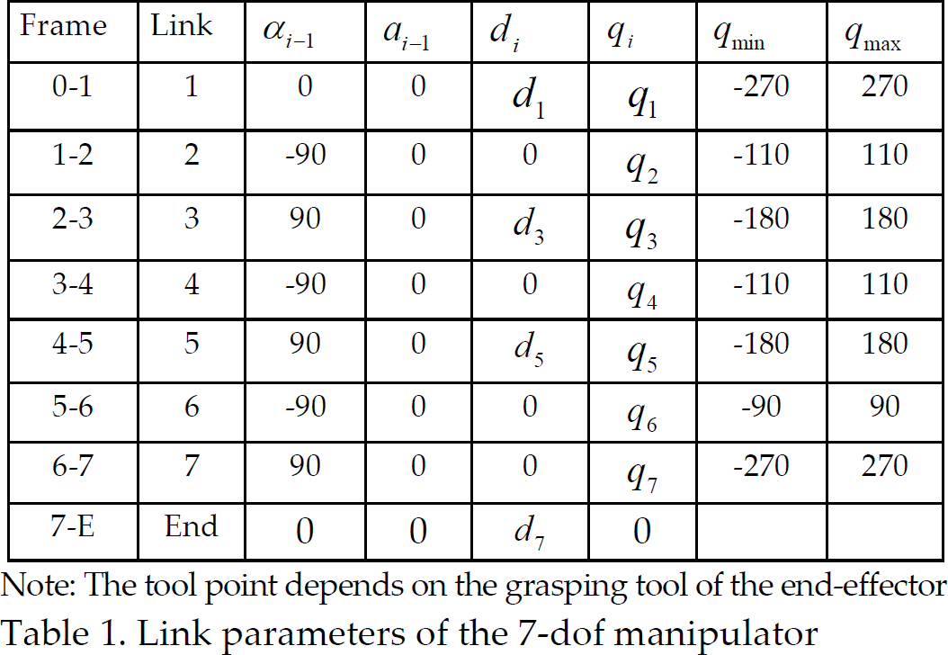
Note: The tool point depends on the grasping tool of the end-effector
Closed-Loop Inverse Kinematics Solution
Assume that a task space trajectory (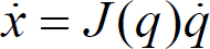
Due to the non-square Jacobian matrix for seven-DOF manipulator, the basic inverse solution to (1) is obtained by using the pseudoinverse J† of the matrix J and the inverse solution can then be written as

where the pseudoinverse J† can be computed as J† = J T (JJ T )−1.
For a kinematically redundant manipulator, a nonempty null space exists due to the excess of input space relative to the manipulable space (n > m), which is available to set up systematic procedures for an effective handling of redundant DOFs (de Wit 1996, Angeles 2002). The null space is the set of task space velocities that yield null joint space velocities at the current robot configuration and these task velocities belong to the orthogonal complement of the feasible task space velocities.
A common method of including the null space in a solution is the formulation in (Liegeois 1977),
Thus the general inverse solution can be written as

where the matrix (I - J†(q)J(q)) is a projector of the joint vector
Because open-loop solutions of joint variables through numerical integration unavoidably lead to solutions drift and then to task space errors, in order to overcome these drawbacks, a CLIK algorithm is utilized which is based on the task space error (e) between the desired and actual end-effector locations or the task space velocity error (ė).
Redundancy
The 7-DOF manipulator includes redundancy since the number of joints (n = 7) is greater than the dimension of the manipulation variables with three position coordinates and three orientation angles (m = 6). Redundancy plays an important role in the kinematic control as redundant joints allow a manipulator to avoid joint limits, singularities or obstacles, the redundancy is also utilized to minimize joint velocities or actuator torques in case of following a desired end-effector trajectory. Due to the existence of redundancy, joint velocities can not be obtained directly by solving the differential kinematics equation since the inverse of non-square matrix J can not be obtained.
In the case of controlling a redundant manipulator (Antonelli et al. 2009), Cartesian space control inputs should be projected into joint space and redundancy can be resolved at position, velocity, or acceleration level based on different application requirements. Here we will focus on the redundancy resolution schemes proposed at velocity or acceleration levels.
Redundancy resolution at the velocity level
As shown in Fig. 2(a), the CLIK algorithm with redundancy resolution at the velocity level is given out, where the Proportional-Derivative (PD) feedback loop regulates the input of the redundancy resolution and the actual end-effector locations flow into the PD part.

Two kinds of closed-loop inverse kinematics schemes with different redundant resolutions
It is obvious that the expression of the location error and its derivative can be given by
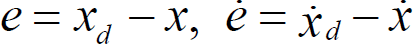
The joint velocity vector has to be chosen so that the task error tends to zero. The pseudo-inverse solution (Carignan 1991; Angeles 1992) at the velocity level results in a minimum-norm velocity solution and the generalized CLIK algorithm can be expressed by

Combining (5) and (1) together, there will be

where K p is a symmetric positive definite matrix, and the choice of K p guarantees that the error uniformly converges to zero.
Using CLIK algorithm, both position and velocity can be obtained for given joint position and velocities and the tracking error along the given trajectory converges to zero with a rate depending on the eigenvalues of K p while open-loop schemes can not achieve.
Similarly, combining (6) and (3) together, the general inverse solution of a kinematically redundant manipulator at the velocity level based on the CLIK algorithm will have the following form:

Some applications like compliant control of redundant manipulators in task space will require redundancy resolution performed at the acceleration level (Shadpey et al. 1995). The second-order differential kinematics equations have the following form:

Then the joint acceleration can be solved by the pseudo inverse of the Jacobian matrix:

where q P denotes the joint accelerations in the task space of the Jacobian or the augmented Jacobian.
The pseudo-inverse solutions aim at minimizing the norm of the joint acceleration, but it leaves the joint velocities in the null-space untouched. The reason is that the joint velocities are composed of two parts,
Then a PD part for Cartesian velocity is added as shown in Fig. 2(b). The actual end-effector locations and task space velocity are the feedbacks to the augmented PD loop and the redundancy resolution is solved at the acceleration level. The joint accelerations of the main task can be solved as:

where
Then by numerical integration, the velocity solution can be obtained.
From previous sections, it is easy to know that if the null space is ignored, many of the redundancy advantages will be lost. Since the equation (7) evidences the possibility of choosing the vector so as to exploit the redundant DOF while the matrix (I - J†(q)J(q)) projects the joint vector
Modifying the null-space will lead to an infinite number of solutions, in fact, the contribution of 
with k0 > 0, w(q) is a scalar objective function of the joint variables and (∂w(q)/∂q) T is the vector function representing the gradient of W.
Many techniques of redundancy resolution are used to search the null space, therefore the search directions and the solutions are determined by evaluation of chosen performance criteria. The works (Kapoor et al. 1998; Hooper & Tesar 1995) presented detailed discussions about performance criteria from two aspects of constraint-based criteria and operational goal-based criteria, while the former includes joint limit avoidance, velocity limit avoidance, peak torque avoidance, obstacle avoidance and mathematical singularity avoidance and the latter considers dexterity, speed of operation, load carrying capacity, manipulator precision, energy minimizing and other criteria.
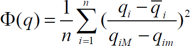
Note that just the joint limit avoidance is considered as local optimization of a performance criterion in this work, and the objective function is the distance from mechanical joint limits (de Wit et al. 1996; Liegeois 1977), which can be defined as
where q
iM
(q
im
) denotes the maximum(minimum) limit for q
i
and
As the quadratic form of equation (12) is the most used function to be minimized, another optimization approach which reflects the objective of joint limit avoidance has been proposed in (Wang & Li 2009; Klein 1984) as:
where p ⩾ 2 and we set p = 6 in the case studies. The CLIK algorithm considering joint limits avoidance as a kind of performance criterion is represented in block scheme form as shown in Fig. 2.
Two case studies are presented to validate the proposed redundancy resolution at the velocity and acceleration levels and the corresponding experiments are done on a real redundant manipulator.
The simulations are carried out in the Matlab/Simulink environment, and a 7-DOF manipulator used in the simulation is composed of seven Powercube modular parts, which is built up with the same geometrical size as the real manipulator. The frame assignments and their transformations are given out in Fig. 1. The corresponding D-H parameters of joints and the maximum and minimum joint values are shown in Table 1. The link length parameters are d1 = 0.301m, d3 = 0.350m, d5 = 0.308m and d7 = 0.4206m. All the joints initial velocities are set to zero at the starting points. The gain parameters have the values, K p = diag{50, 50, 50} and K v = diag{50, 50, 50}, and the simulation time is set to 4 s.
Case study 1
In the first case study, the desired spatial trajectory is defined as an ellipse with major radius 0.35m and minor radius 0.15m in the XZ plane of Cartesian coordinates.
In order to show the effectiveness of the JLA objective function, the simulations are firstly done with the consideration of JLA and without JLA respectively. Then the redundancy resolution at the velocity and acceleration levels are both considered in the following simulations. From the simulation results shown in Fig. 4, it is easy to find that the sixth joint exceeds its upper joint limit (90 deg) from Fig. 4(b) whereas the joints limits are successfully avoided in the simulation results using the JLA optimization approach (13) as shown in Fig. 4(d) and Fig. 4(f). The manipulator's configuration during the simulation is shown in Fig. 4(a), where the redundancy resolution combines the JLA optimization approach.

A real seven-DOF redundant manipulator

Simulation results of the seven-DOF manipulator tracking a spatial ellipse. (c) and (d) are generated at the velocity level while (e) and (f) are generated at the acceleration level.
The joints velocities of redundancy resolution at the velocity and acceleration level are shown in Fig. 4(c) and Fig. 4(e). By comparing them, it is not difficult to find that the joint velocities converge to zero in the former one whereas the latter is not. The reason is that the redundancy resolution at the velocity level results in a minimum-norm velocity solution and it does not have any null space component.
The corresponding experiment is made on a real Powercube manipulator as shown in Fig. 3. The following trajectories in the simulation and experiment are combined together with the desired spatial ellipse trajectory as shown in Fig. 5 and the projection on the plane is shown in Fig. 6.
Simulation, experiment and desired spatial ellipse trajectories

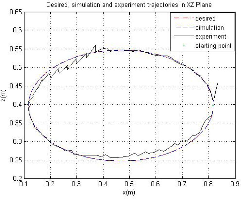
Simulation, experiment and desired spatial ellipse trajectories projected on the XZ plane
Errors of tracking an ellipse trajectory in the simulation and experiment are presented respectively in Fig. 7(a) and Fig. 7(b). Experimental errors seem much bigger than the simulation errors because of many uncertainties such as unknown inertia dynamics, complex nonlinear frictions, gears reduction clearances, motor rotating drift and so on.

Errors of tracking an ellipse trajectory in the simulation and experiment. Errors_A represents the errors between the simulation and desired trajecotory while error_B means the errors between the experiment and desired trajecotory.
The second case study is to track a trajectory with the shape of “U”. Similarly as case study 1, the simulations are made respectively with the redundancy resolutions at the velocity and acceleration levels.
The manipulator configuration tracking the U-shape trajectory is shown in Fig. 8(a). The joint angles of the solution without considering JLA optimization approach is shown in Fig. 8(b), where all the joints do not exceed their limits since this kind of task doesn't lead to the disruption of any joint limits. The joint angles solved in the simulations with redundancy resolution at the velocity and acceleration levels are shown in Fig. 8(c) and Fig. 8(d) respectively.

Simulation results of the seven-DOF manipulator tracking a U-shape trajectory. (c) and (d) are generated at the velocity level.
Three kinds of trajectories (simulation, experiment and desired trajectories) are combined together and compared in Fig. 9 and their projections on the XZ plane are shown in Fig. 10. The tracking errors for the U-shape spatial trajectory in the simulation and experiment are presented respectively in Fig. 11(a) and Fig. 11(b). Although there are many uncertainties that lead to the unexpected errors, the experiments have shown desired results.

Simulation, experiment and desired spatial U-shape trajectories
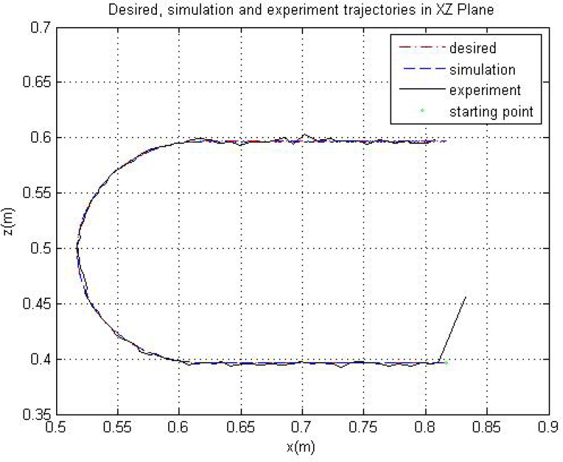
Simulation, experiment and desired spatial U-shape trajectories projected on the XZ plane

Errors of tracking a spatial U-shape trajectory in the simulation and experiment. Errors_A represents the errors between the simulation and desired trajecotory while error_B means the errors between the experiment and desired trajecotory.
In this paper, joint limit avoidance is applied as an optimization approach to solve the redundancy by the gradient projection method (GPM) (Liegeois 1977). GPM solves the inverse kinematics problem at the velocity level and can only deal with performance criteria defined at the position level. Besides, many other performance criteria such as velocity limit avoidance, peak torque avoidance, obstacle avoidance, mathematical singularity avoidance and energy minimization can be selected (Kapoor et al. 1998; Lee & Buss 2006). Redundancy resolution can be at different levels, like joint displacements, velocities, acceleration or torques. Mostly the redundancy is resolved at one particular level while sometimes criteria defined at different levels are combined together for an optimal solution. However, most of above performance criteria are coupled. Then it is impossible to optimize one criterion without affecting another and the tasks with different priorities will be regulated (Antonelli et al. 2009).
Conclusions
The inverse kinematics solutions of a redundant 7-DOF manipulator is resolved based on the CLIK algorithm and the redundancy resolutions are found at the velocity and acceleration levels respectively. Two kinds of case studies are considered and the corresponding simulations and experiments are made respectively. The joint limit avoidance is considered as one performance criterion with local optimization, which is combined into the redundancy resolution as a null-space optimization approach and its effectiveness is proved by the numerical simulation results. Based on two proposed CLIK schemes, the kinematics solutions with redundancy resolution at the velocities and acceleration level are compared and analyzed. Although there are many uncertainties leading to the unexpected errors, the experimental results confirm the proposed method.
Footnotes
7. Acknowledgements
This work is supported by the Macao Science and Technology Development Fund under Grant no. 016/2008/A1 and Research Committee of University of Macau under grant no. UL016/08-Y2/EME/LYM01/FST.
1
Note that all the links of 7-DoF arm are rigid.