
Abstract
Obstacle avoidance can be achieved as a secondary task by appropriate inverse kinematics (IK) resolution of redundant manipulators. Most prior literature requires the time-consuming determination of the closest point to the obstacle for every calculation step. Aiming at the relief of computational burden, this paper develops what is termed a backward quadratic search algorithm (BQSA) as another option for solving IK problems in obstacle avoidance. The BQSA detects possible collisions based on the root property of a category of quadratic functions, which are derived from ellipse-enveloped obstacles and the positions of each link's end-points. The algorithm executes a backward search for possible obstacle collisions, from the end-effector to the base, and avoids obstacles by utilizing a hybrid IK scheme, incorporating the damped least-squares method, the weighted least-norm method and the gradient projection method. Some details of the hybrid IK scheme, such as values of the damped factor, weights and the clamping velocity, are discussed, along with a comparison of computational load between previous methods and BQSA. Simulations of a planar seven-link manipulator and a PUMA 560 robot verify the effectiveness of BQSA.
Keywords
1. Introduction
The redundancy of manipulators can be used to achieve secondary goals, such as joint limits avoidance [1], obstacle avoidance [2–4], minimization of joint torque [5], etc., without disturbances to the main task [6]. In order to drive redundant manipulators, an appropriate sequence of joint velocities is generated from the desired velocity of the end-effector and the predefined constraints of the inverse kinematics (IK) [7]. However, the underdetermined ability of the Jacobian matrix would result in infinite IK solutions and a probable singularity [8]. This is the primary difficulty in the application of redundant manipulators. Thus, prior literature [9] has proposed abundant methods, including damped least-squares (DLS) [10], gradient projection (GP) [11], weighted least-norm (WLN) [1] and augmented, or extended, Jacobian matrix (AJM or EJM) [7, 12] methods to cope with these difficulties.
Obviously, it is essential to drive manipulators to avoid collisions with obstacles, and this secondary goal has inspired the development of a variety of methods. Some of the prior literature achieved obstacle avoidance kinematically based on the determination of the closest point to the obstacle (called the obstacle avoidance point). A. A. Maciejewski and C. A. Klein [2] calculated the obstacle avoidance point based on a Jacobian matrix and the end-effector velocity, and utilized the GP method to achieve obstacle avoidance with lower priority. F. T. Cheng, T. H. Chen, Y. S. Wang and Y. Y. Sun [13] formulated the IK problem of redundant manipulators considering obstacle avoidance and drift-free criteria using compact quadratic programming (QP). Y. N. Zhang and J. Wang [14] improved the equality-based QP formulation in [13] to create an inequality-based one, and used a dual neural network to generate joint velocities. Recent progress in the kinematical method of obstacle avoidance can be found in [15–17]. Nevertheless, these methods require the identification of the obstacle avoidance point for every calculation step, which is time-consuming and sometimes difficult when the obstacle contour becomes complex. On the other hand, some researchers have resolved the problem at a dynamical level. O. Khatib [3] established an artificial potential field around obstacles and substituted potential forces into the dynamical equation of manipulators. The application of harmonic potential functions can be seen in [4], and some other definitions of potential functions have been provided in recent work [18,19]. However, methods based on artificial potential field achieve obstacle avoidance in a dynamical way and are not applicable when manipulators’ dynamical parameters, such as link masses, positions of mass centres, inertias, etc., are unknown. Thus, a kinematical method for obstacle avoidance involving less calculation burden is eagerly anticipated.
This is the motivation of the present paper. Since the obstacle avoidance point is located between the two end-points of each manipulators’ link, and because the trajectories of all end-points can be easily obtained during calculation, it is naturally expected that the detection and avoidance of possible collisions depend on the relationship between obstacles and the manipulators’ end-points alone. Assuming that all obstacles can be enveloped by different ellipsoids, this paper will reveal the categories of collision based on the property of a derived quadratic function. Utilizing some recent IK algorithms [20–22] dealing with unilateral constraints, a backward quadratic search algorithm (BQSA) is developed to control redundant manipulators moving along desired end-effectors’ trajectories, as well as away from obstacles, by employing a hybrid scheme of GP and WLN methods.
The rest of this paper is arranged as follows. Section 2 presents the geometrical model of the problem and a hybrid IK scheme. Collisions are divided into several categories based on the derived quadratic function, and the basic procedure and determination of parameters of the BQSA are introduced in Section 3. Section 3 also compares the computational load between a previous kinematical method and the BQSA. A seven degree-of-freedom (DOF) planar serial-link manipulator and a PUMA 560 robot are numerically simulated, respectively, to validate the effectiveness of the proposed algorithms in Section 4. Finally, Section 5 presents the conclusions of this paper.
2. Problem Formulation
2.1. Geometric modelling
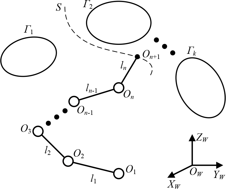
The geometric model of manipulators and obstacles is depicted in Figure 1. Neglecting the shapes of all links and joints, the manipulators have n DOF with links (line segments in geometry) and joints (dots in geometry) denoted as l
i
and O
i
(i = 1, 2,…, n), respectively. All obstacles are assumed to be enveloped by k ellipsoids (called obstacle enveloped ellipsoids, OEEs) denoted as Γ
j
(j = 1, 2,…, k). The world coordinates are denoted as O
W
,X
W
,Y
W
,Z
W
. The manipulator is fastened on a base O1 and its end-effector On+1 moves along the trajectory S. For every time period of calculation, the location and shape of all enveloped ellipsoids and the position of the end-effector On+1 are given relation to the world coordinate. Assume that On+1 is never in contact with obstacles, which can be assured by the programming of the end-effector's trajectory
Here, all obstacles are assumed to be enveloped in ellipsoids that have smooth convex contours and can be determined according to nine parameters, including its centre location, axis length and axis direction. Most obstacle shapes (such as points, rectangles and triangles, etc.) can be conservatively included in the ellipsoid, and some can even be obtained from the deformation of an ellipsoid. Take a wall obstacle, for instance, and denote the three ellipsoidal axis lengths as a, b and c, respectively. If a >> b, then the ellipsoidal obstacle approximately deforms into a wall with a as the length, b as the thickness and c as the height. This state of affairs is illustrated in Figure 20. Another benefit of ellipsoidal obstacles is the quadratic property of their analytical expression thanks to which this paper's proposed BQSA can easily detect possible collisions between manipulator links and obstacles with minimal computational burden. This point will be discussed in further detail in Subsection 3.4.
Geometric model of redundant manipulators and obstacles
Generally, manipulators move and OEEs are shaped in the three-dimensional Euclidean space. The collision between manipulators and OEEs can be avoided by one of the three two-dimensional link-obstacle pairs, which are the projections of the three-dimensional link-obstacle pairs to three mutually orthogonal planes that avoid the collision. This proposition is depicted in Figure 2 and further proved by Lemma 1.

Collision avoidance between manipulators and OEEs: a three-dimensional and three mutually orthogonal planar situation
The converse negative proposition of Lemma 1 indicates that, if the collision happens between the three-dimensional link-obstacle pair, all of the three planar-projected pairs are involved in the collision. However, the negative proposition of Lemma 1 is incorrect. Thus, planar obstacle avoidance can be adopted as a conservative way to assure three-dimensional obstacle avoidance, which simplifies the problem to a two-dimensional situation. The following discussions in this paper are conducted in the xoy plane and analytical equations for the i-th link and the j-th obstacle ellipse can be written as

and

respectively. The end-points of the i-th link are denoted as (x i , y i ) and (xi+1, yi+1), and parameters of the line segment can be obtained as

Parameters of the j-th obstacle ellipse, including A j , B j , C j , D j , E j , and F j , are assumed to be known at every time period of calculation.
2.2. Hybrid scheme of inverse kinematics
Let

with the initial configuration

in which vectors
The aim of the inverse kinematics is to resolve an appropriate sequence of joint velocity

in which the matrix

where the matrix
The self-motion that arises from the redundancy of the manipulator can be utilized to achieve secondary tasks, such as joint limits avoidance, obstacle avoidance, etc. without any disturbances to the primary task. GP is one such method [11], projecting secondary goals into the null space of the Jacobian matrix, which can be written as

in which μ > 0 is the gradient rate,

in which

Define the weighted Jacobian matrix and joint velocity as

and the singular value decomposition (SVD) of

where the matrix

and

with r ≤ m as the rank of

in which the velocities
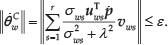
The DLS [10] can effectively increase the Jacobian singular robustness and is utilized to avoid a potential Jacobian singularity. Nevertheless, as the non-zero damping factor λ will decrease the accuracy of the main task, which can be indicated as the reprojection error [9], defined as follows

it is better to take the zero value for the damping factor when the Jacobian matrix does not approach the singularity; when the Jacobian singularity occurs, the value for the damping factor should be positive but as small as possible. The detailed method to determine the value of λ is presented in Lemma 2.

the trajectory tracking task can be bounded by ε which is an arbitrary positive number, e.g.
In this paper, obstacle avoidance is considered as the secondary task and the WLN method is utilized to enforce this constraint. However, the traditional WLN method [1] will result in the loss of DOF, so the clamping velocity to the kernel of the weighted Jacobian by the GP method [22] is added to the WLN scheme. These two measures are presented in subsection 3.3 in further detail.
It should be noted that there is not always a feasible solution for the IK problem with constraints like joint limits and obstacle avoidance. One of the most significant factors influencing the feasibility of the IK problem is the manipulator's redundancy. Considering an n-DOF manipulator, the primary trajectory tracking mission will cost m DOF, and the rest of n-m DOF represents the manipulator redundancy which can be utilized to achieve secondary goals. In order to guarantee the feasibility of the IK problem, the consumption of DOF by the constraints must be less than n-m, otherwise no optimal solution can be obtained.
3. Backward Quadratic Search Algorithm
3.1. Quadratic category of collisions
According to the problem formulation, obstacle avoidance is modelled as the geometrical relationship between a line segment and an ellipse. Generally, assume

the coefficients of which can be obtained as

Furthermore, define Δ ij and {x1ij, x2ij} as

and

respectively. The collision between the i-th link and the j-th obstacle can be determined via the root property of the quadratic function (19), which is dependent on Eq. (21) and Eq. (22), and can be divided into five categories, depicted in Figure 3. The five quadratic categories of collisions can be expressed as follows:
Thus, the collision between the link and the obstacle can be determined by calculating the root discriminant Δ ij of the quadratic equation f ij = 0 and the function of its derivative values of both end-points of the link. Since the position for each end-point can be conveniently obtained at every calculation step, this method is much easier than that in [2], which requires a search for the obstacle avoidance point and the calculation of the minimum distance.
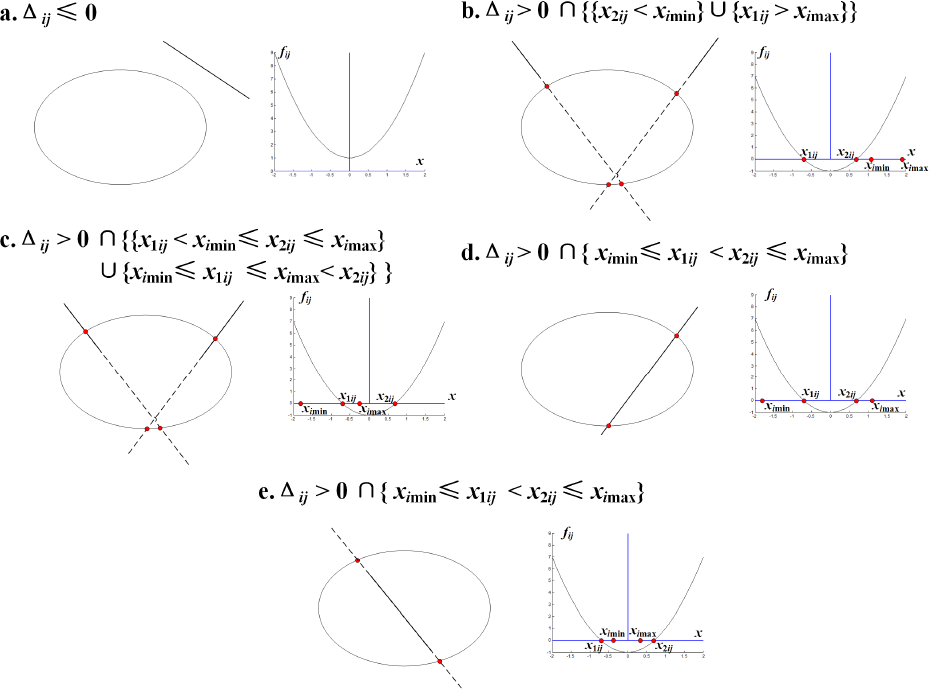
Quadratic categories of collisions
3.2. Basic procedure of BQSA
Assume that the initial configuration of the manipulator avoids all obstacles and the trajectory of the end-effector has been appropriately programmed outside all obstacles. The backward quadratic search algorithm (BQSA) combines the proposed hybrid scheme of IK with the root properties of derived quadratic functions f ij (i = 1, 2,…, n, j = 1, 2,…, k) to generate joint velocity and guarantee obstacle avoidance. To assure the feasibility of the solution, the inequality n - m ≤ k should be satisfied.
Since the end-effector always moves outside obstacles, the collision detection can be conducted from link l
n
Thus, the word ‘
for t = δt, 2δt,…

in which vectors
Details of Step 4 (Joints Clamping), including the determination of θi+1,tt (t), geometrical computation of p i (t) and θ i (t) etc., are discussed further in subsection 3.3 to elucidate the effect of the clamping velocity.

Basic procedure of the backward quadratic search algorithm
3.3. Discussions on joints clamping
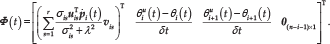
Following the detection of collisions, the BQSA enters into the joints clamping step before updating and outputting the kinematical resolutions. The algorithm makes this choice automatically by setting the value of the weighted matrix, which can be expressed as

The weighted matrix
Elements of the clamping velocity φ1(t)~φi+1(t) are actuated in the Jacobian null space when link l i becomes involved in a collision with the obstacle, and the remaining elements of the clamping velocity φi+2(t)~φ n (t) are set to zero. Assuming tt = 1, 2, 3,… according to the while loop inner counter in Step 4, the value of θi+1(t) is adjusted as

where θi+1,tt(t) denotes the value of the i+1-th joint angle at the tt-th step in the while loop and the t-th step in the for loop, and θi+1,-1(t) = θi+1,0(t) incorporates the value of θi+1(t) in Step 3. The adjustment Δθ is assigned a minutely positive value as the increment of |θi+1,tt(t)| for every computation step in the while loop. Once link l i is moved away from the obstacle as detected in Step 4, the clamping adjustment of θi+1(t) ends and the renewed value of θi+1(t) and the clamping velocity element φi+1(t) can be obtained as θi+1 u (t) = θi+1,tt(t) and φi+1(t) = (θi+1 u (t) - θi+1,1(t))/δt, respectively.
Subsequently, the position of the end-point O i can be geometrically computed as

in a planar case. Note that BQSA will not affect

in which vectors
Finally, the updated value of θ i u (t) can be geometrically computed as

in which the symbol <
3.4. Discussions on computational load
As mentioned above, the proposed BQSA is motivated primarily by the aim of relieving the computational load. A comparison of computational complexity between traditional kinematical methods for two-dimensional obstacle avoidance and BQSA is discussed in this subsection.
In prior literature [2, 13, 15–17], kinematically redundant manipulators’ obstacle avoidance is dependent on the real-time determination of the obstacle avoidance point, contributing the greater portion of the method's computational load. Without the assistance of extra sensors, like laser range finders, cameras, etc., the search for the obstacle avoidance point that is least far from the obstacles on the links in the structured environment is conducted based on the computation of the Euclidean distance between every point on the obstacles’ surface and manipulator links, for every iteration step. Considering the scenario depicted in Figure 1, assume that the i-th (i = 1, 2,…, n) manipulator link consists of N
i
test points and the j-th (j = 1, 2,…, k) obstacle consists of M
j
test points, respectively. The position of every test point is assumed to be known, and the computation of the Euclidean distance between every single test point pair results in double multiplication. Moreover, there are
Nevertheless, the BQSA achieves obstacle avoidance without searching for the obstacle avoidance point, but rather by determining the states of collisions based on the position of end-points for every link and the shape of every elliptical obstacle. Assume that the position (ximin, ximax) for i = 1, 2,…, n and parameters {A j , B j , C j , D j , E j , F j } for j = 1, 2,…, k is given. According to Eqs. (3) and (16), 22 times of multiplications is consumed to determine the quadratic function f ij (x). Furthermore, for the computation of the criterion of root Δ ij and roots {x1ij, x2ij}, three further multiplications are required, indicated by Eqs. (21) and (22). Referring to the same scenario consisting of n links and k obstacles, as depicted in Figure 1, it will repeat the above computation processes nk times for every iteration and, hence, the computational complexity of collision detection reaches O (25nk).
Assuming that N = min{N i , i = 1, 2,…, n } and M = min{M j , j = 1, 2,…, k }, the following inequalities can be derived as

and

Therefore, the computational complexity of the BQSA will be lower than previous kinematical methods based on the determination of the obstacle avoidance point, as long as NM > 12.5, which is satisfied in most situations. Eq. (30) also indicates that the improvement in computational load for the BQSA increases as the number of test points increases, but has no relationship to the number of links or obstacles. Hence, the relief of computational burden achieved by the BQSA is reasonable for most situations with an arbitrary number of manipulator links and obstacles.
In order to demonstrate the reduction in computational load achieved by the BQSA as compared with previous methods, the cost of computation time versus the number of test points for each obstacle-link pair (i.e., the value of NM) and the total number of links and obstacles (i.e., the value of nk) are respectively calculated using data from statistical experiments. The statistical results are displayed in Figure 5 and Figure 6, respectively. Data in each figure are the averages of 100 repeated tests conducted using a Matlab program run on a Intel(R) Core(TM) i7-4770 CPU @ 3.40 GHz.
Setting nk = 27, Figure 5 illustrates a linear relationship between computation time for the test of obstacle avoidance points and the value of NM, while the computation time for the BQSA is little influenced by the value of NM. Obviously, for most situations (when NM > 100), the BQSA requires less computation time and the benefit of the BQSA for time consumption grows as the value of NM increases. Thus, for most obstacle shapes (excluding points and lines), the BQSA can clearly relieve the computational burden as compared to present kinematical methods proposed in the existing literature. As obstacles’ shapes become more complicated, this benefit in computational load will become even more pronounced.
The computation time consumed by both previous methods and the BQSA, where NM = 600 and the total number of links and obstacles (i.e., the value of nk) is increased, is depicted in Figure 6. Both curves increase linearly as the value of nk increases, and both the computation time and the slope of the obstacle point test are obviously greater for the existing methods than for the BQSA. This phenomenon thereby verifies the relief of computational load by the BQSA from another perspective.

Computation time versus ‘NM’ when the value of nk is fixed to 27
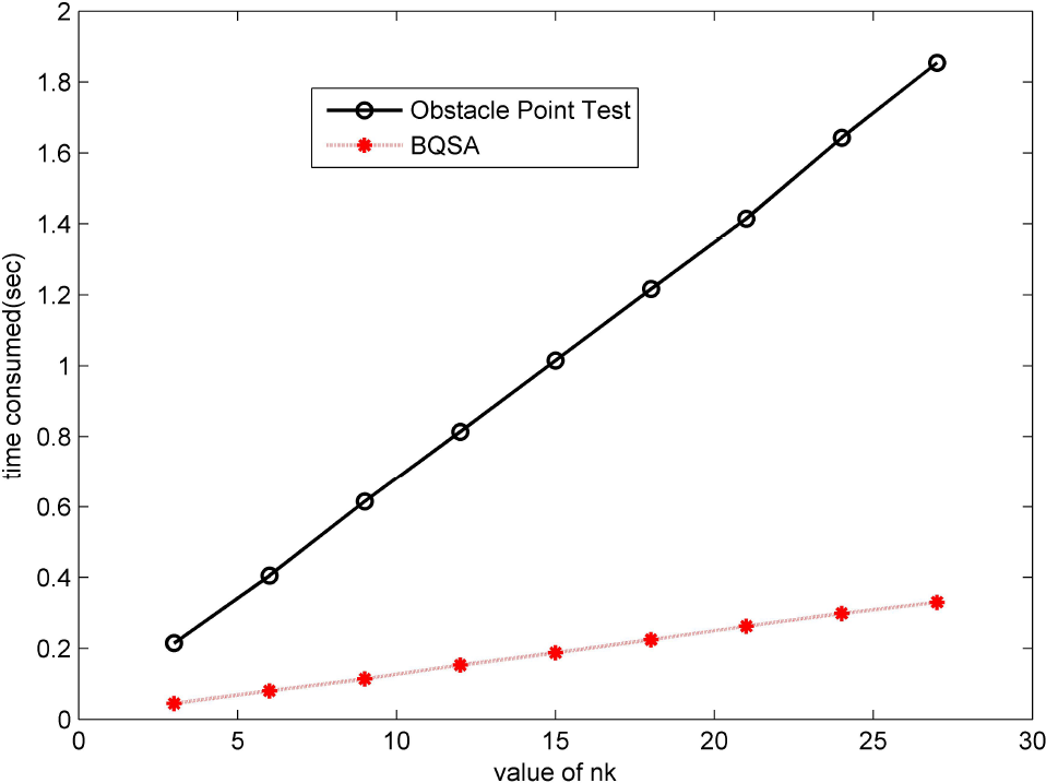
Computation time versus ‘nk’ when the value of NM is fixed to 600
4. Numerical Simulations
4.1. A seven-DOF planar manipulator
Since three-dimensional obstacle avoidance can be guaranteed by three mutually orthogonal two-dimensional obstacle avoidance processes, as indicated by Lemma 1, a planar case is numerically simulated to verify the effectiveness of the proposed BQSA. The simulation scenario is depicted in Figure 7, in which a planar seven-link manipulator is expected to move its end-effector along the surface of an elliptic object while avoiding an elliptic obstacle. The shape and location of both the elliptic object and obstacle are assumed to be known before the resolution of IK, and the parameters specification of the simulation are summarized in Table 1. The seven-DOF planar manipulator is obviously redundant since the planar trajectory tracking mission only consumes two DOF. Therefore, the manipulator has five extra DOF to be utilized for the obstacle avoidance task.

Simulation scenario: a planar seven-DOF manipulator is expected to move its end-effector along a desired trajectory on the surface of an elliptic object, avoiding collisions between the object and an elliptic obstacle
Parameters specification of the simulation of a planar manipulator

Depicted as Figure 8, manipulator configurations obtained by BQSA illustrate an avoidance of the elliptic obstacle without deviation from the desired end-effector trajectory. It should be noted that the collision involving the object is unexpected, so the avoidance of the object is also necessary during the simulation. The trajectory tracking is considered the main task, which requires at least two DOF to guarantee tracking accuracy, and the redundancy of the remaining five DOF for the seven-link manipulator is utilized to achieve the secondary task of avoiding collision with both the obstacle and the object.
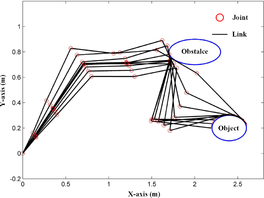
Manipulator configurations illustrating the trajectory tracking by the end-effector, as well as obstacle avoidance utilizing BQSA
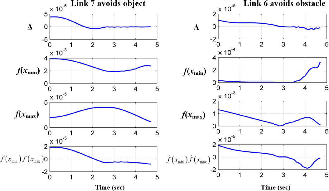
Criteria of the quadratic categories of collisions as defined in Figure 3, where possible collisions occur only between link seven and the object, and link six and the obstacle
According to the results of collision detection, possible collisions only occur between link seven and the object, and link six and the obstacle. Figure 9 depicts the value of classification criteria of the quadratic categories, as defined in Figure 3. The manipulator configurations satisfy either Δ ≤ 0 or Δ > 0 ∩ f(xmin) > 0 ∩ f(xmax) > 0 ∩ df(xmin)/dx⋅df(xmax)/dx > 0, which belong to either the no collision 1 or no collision 2 categories, as outlined in Figure 3. The results demonstrated in Figure 9 verify the effectiveness of collision detection based on quadratic categories, and are compatible with the manipulator configurations shown in Figure 8.
Figure 10 compares the desired end-effector trajectory and the practical trajectory. Clearly, the manipulator can achieve an accurate trajectory tracking mission, even though the tracking precision decreases slightly as the manipulator avoids the obstacle. A further illustration of the tracking performance is depicted in Figure 11, which shows that the tracking errors along both the x-axis and y-axis are below 3.5 mm. Figure 11 also illustrates smooth trajectory tracking when the manipulator meets no obstacles, while the end-effector moves non-smoothly as the manipulator encounters and actively avoids obstacles.

A comparison of the desired end-effector trajectory and the practical trajectory

Trajectory tracking errors along both the x-axis and y-axis
The seven joint angles are depicted in Figure 12, which displays continuous but clearly non-smooth curves. The non-smooth aspect arises when the manipulator encounters and avoids the obstacles, and indicates a discontinuous property for joint velocities during obstacle avoidance. This phenomenon is compatible with the characteristics of the BQSA, shown as Eqs. (24) and (27).

Joint angles during the manipulation
4.2. A demonstration of a PUMA 560 robot
In order to verify the feasibility and effectiveness of the BQSA for three-dimensional situation, numerical simulations are conducted on a PUMA 560 robot. The configuration and the Denavit-Hartenberg (DH) coordinates are depicted in Figure 13 and the DH parameters are summarized in Table 2. The robot has six DOF in total, and the trajectory tracking mission costs three DOF. The remaining three DOF can be utilized for the obstacle avoidance task.
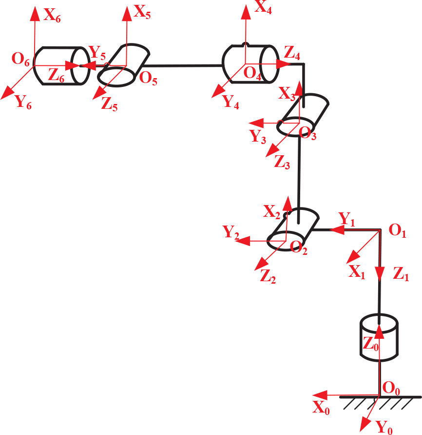
The configuration and the DH coordinates of the PUMA 560 robot
DH parameters of the PUMA 560 robot
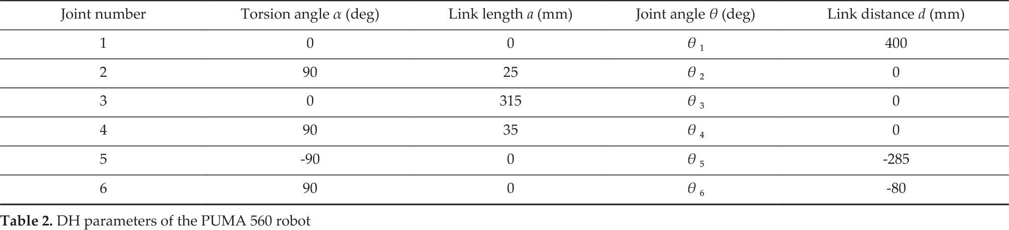
During the manipulation task, the robot starts from an initial state with joint angles set as θ = [0; −60; 90; 0; 10; 0] deg and tracks a circular trajectory with 100mm as the radius, located in the YOZ plane by its end-effector. At the top section of the trajectory, the end-effector collides with an ellipsoidal obstacle whose centre is located at (547, 0, 634) mm and the three axis lengths of which equal 20 mm, 100 mm and 60 mm, respectively. By projecting the three-dimensional robot configuration to the XOZ plane, the BQSA achieves the two-dimensional elliptic obstacle avoidance, which is illustrated in Figure 14. Assured by Lemma 1, the robot can succeed in avoiding the ellipsoidal obstacle in the three-dimensional space, as depicted in Figure 15. Moreover, the obstacle avoidance and the effectiveness of the collision detection by the quadratic categories defined in Figure 3 can also be illustrated by the value of criteria shown as Figure 16, in which the data satisfy either Δ ≤ 0 or Δ > 0 ∩ f(xmin) > 0 ∩ f(xmax) > 0 ∩ df(xmin)/dx⋅df(xmax)/dx > 0. This phenomenon is compatible with the collision-free quadratic category and indicates obstacle avoidance.

PUMA 560 robot configurations illustrating the end-effector trajectory tracking and obstacle avoidance utilizing BQSA, projected from the three-dimensional space to the XOZ plane
Depicted in Figure 17, the comparison of the desired and the practical circular trajectories demonstrates accurate trajectory tracking by the end-effector. However, when the BQSA activates obstacle avoidance, the tracking trajectory becomes a little less smooth and deviates from the desired path. As shown in Figure 18, the tracking error along the x-axis is less than 1 mm, and along the y-axis is less than 4 mm. The largest tracking error, of approximately 20 mm, occurs on the y-axis, which is reasonable given that the BQSA is performed on the XOZ planar projection of the robot. The joint angles shown in Figure 19 have similar shape properties to the curves shown in Figure 12. The non-smooth change occurs when the robot avoids the obstacle, which indicates a discontinuity in joint velocities and accords with the weighted characteristics of the BQSA.
Aiming to illustrate the effectiveness of the BQSA with regard to a wall obstacle, the three axis lengths of the ellipsoidal obstacle are set as 0.1 mm, 100 mm and 10000 mm. The ellipsoid thereby approximates a wall, relative to the robot demo. The three-dimensional configurations depicted in Figure 20 illustrates success in avoiding the wall obstacle, achieved by the utilization of the BQSA.

PUMA 560 robot configurations illustrating the end-effector trajectory tracking, as well as obstacle avoidance utilizing BQSA
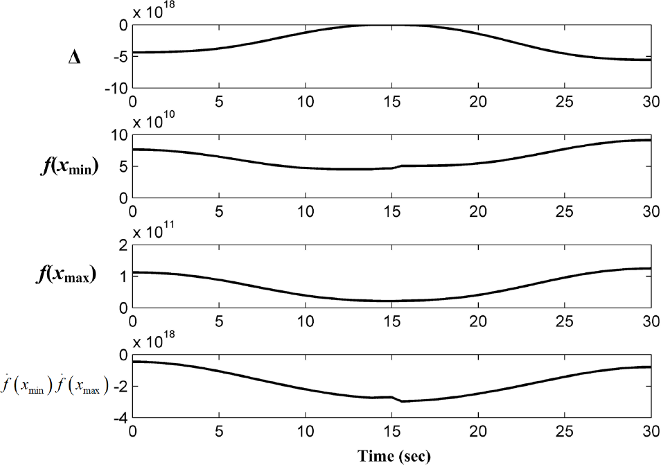
Criteria of quadratic categories of collisions as defined in Figure 3, where possible collisions occur only between the end-effector and the ellipsoidal obstacle
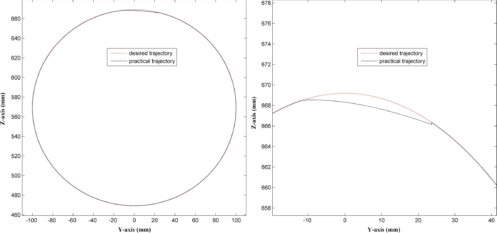
A comparison of a desired and a practical end-effector trajectory
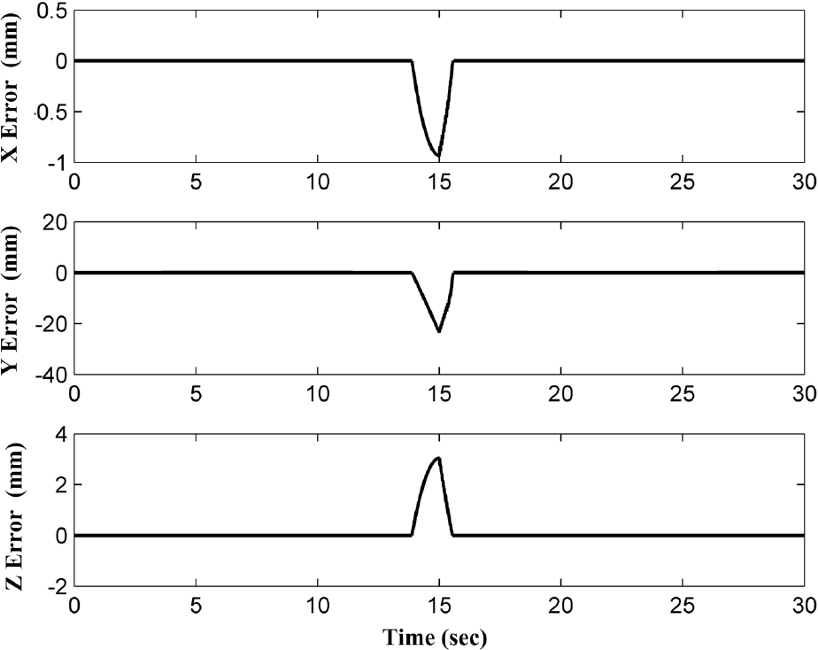
Tracking errors of the end-effector of the PUMA 560 robot along three axes

Joint angles of the PUMA 560 robot during the manipulation

Puma 560 robot configurations during wall obstacle avoidance
5. Conclusions
This paper develops a backward quadratic search algorithm (BQSA) for inverse kinematics (IK) of redundant manipulators, with trajectory tracking as the primary task and obstacle avoidance as the secondary task. As the BQSA uses end-points’ positions, which can be easily obtained, rather than the closest point to the obstacle on each link, the computational burden of IK resolution is expected to be reduced. The design of the backward search ensures that the obstacle avoidance by the i-th link does not deform the configurations of those links labelled as larger than i. The hybrid scheme of IK guarantees obstacle avoidance as the effect of the weighted least-norm method and ensures no loss of degree of freedom by the gradient projection method and the clamping velocity. The effectiveness of the BQSA is verified numerically and the relief of computational load by the BQSA is analysed both theoretically and numerically.
Furthermore, although most of the discussions and simulations are conducted on the basis of planar situations, three-dimensional obstacle avoidance can also be achieved by utilizing the BQSA in three mutually orthogonal two-dimensional planes, as indicated by Lemma 1. Numerical simulations of a PUMA 560 robot support the feasibility and effectiveness of the BQSA in the three-dimensional situation.
Since the PUMA 560 robot is widely used in the design of industrial manipulators, applications of the proposed BQSA are promising and eagerly anticipated. Moreover, obstacle avoidance is only a small subset of the secondary tasks that can be achieved by utilizing manipulators’ redundancy. A series of extra constraints, including joint limits, joint torque minimization, etc., are expected to be addressed in the developed hybrid scheme of inverse kinematics.
Footnotes
6. Acknowledgements
This work was supported by the National Natural Science Foundation of China (Grant no. 11272004). The authors appreciate all the anonymous reviewers for their comments and kind help.