
Abstract
In the field of modeling and simulation of mechatronics designs of high complexity, is presented a systematic analysis of an IEDD unit [1] (improvised explosive device disposal) based in a new methodology for modeling and simulation divided into 6 stages in order to increase the accuracy of validation of whole system, this mechatronic unit is a Non-holonomic Unmanned wheeled mobile manipulator, MU-NH-WMM, formed by a Differential Traction and a manipulator arm with 4 degrees of freedom mounted on wheeled mobile base, hence the contribution of this work is a novel methodology based on a practice proposal of philosophy of mechatronics design, which establishes the suitable kinematics to coupled wheeled mobile manipulator, where the motion equations and kinematics transformations are the base of the specific stages in order to obtain the dynamic of coupled system, validating the behavior and the trajectories tracking, in order to achieve the complex tasks of approaching to work area and the appropiatehandling of explosive device, this work is focused in the first of them; such that the errors in the model can be detected and later confined by proposed control.
Introduction
This Mechatronic Unit EOD/IEDD (explosive ordinancedisposal/improvised explosive device disposal) takes theplace of humans in the work of bomb detection, removal, transportation and detonation (Graham, T., 2006). Bombs thatare difficult to neutralize or demolish because of the location may not be suitable to explode for fear of human injury orbuilding damage. Due to this fact, it is clear the disposaloperation is a big challenge for the operators especially whenthe surroundings are complex and cluttered (State Agency for Civil Protection, 2005).
The MU-NH-WMM is a multi-link arm with ability tomove in a plane or space which is mounted on a vehicle(Zuñiga, L.A., 2008). These systems may have especial andimportant tasks such that these missions can result instabilityleading to overturning. Although the motion of manipulatormay have universe effects on the stability of the card, becauseof dynamic interface between the vehicle and manipulator, the action of manipulator may be controlled to compensatethe threshold of stability (Zuñiga, L.A., 2008).
In previous work, a modeling and simulation proposal for thismechatronic unit was made by considering the mobile unitand the manipulator in a separated way (Ghaffari, A., 2004). Thepresent work considers the modeling and simulation of boththe mobile unit and the manipulator in a coupled way; thisrepresents more accurately the behavior of the whole robot.
The kinematics of the mechatronic unit for its orientation andsteering angle along the path is derived. Next unit dynamicsare derived in terms of path geometry, and the constraints onunit motions are formulated in this work. The stability of the MU-NH-WMM has a close relation with the unit's motion. In this document, the nonlinear equations of the MU-NH-WMM which moves in a vertical plane havebeen derived.
The measure for determining the stability criterion of the MU-NH-WMM is the tires upward force (Bayle, B., 2003). This work is structured first with the explanation about methodology for modeling and simulation, next is presented the case of Approaching to work area using the Stage 2, after is depicted the case of Transport, using ythe Stage 4, in the next section of this document is shown the case of Disposal of explosive device using the stage 5, finally is validated the methodology in the last section.
Modeling and Simulation Methodology
In order to model and simulate the mechatronics unit is necessary to propose a methodology to validate the correct behavior of the coupled system, which considers the interaction between various tools, this interaction is shown in the figure 2. The next proposal methodology is applied for modeling and simulation the behavior of mechatronic unit in the handling task, which is depicted in the next figure.

Block Diagram of Methodology Proposed
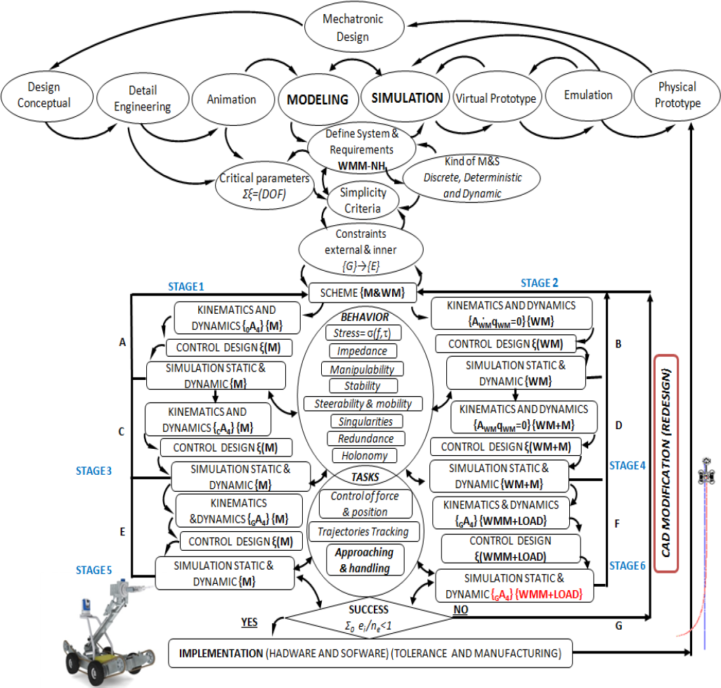
Methodology proposal of M&S
The next proposal methodology is applied for modeling and simulation the behavior of mechatronic unit.
To model and simulate the complete system are considered six stages, which in order to the case of approaching task of explosive device are omitted the stages 1 and 3, in addition the stage 2, 4 and 5 are done according to stage. For modeling the complete system are considered six stages:
The coupled MU-UWMM in steady state, the manipulator uses its 4 degree of freedom for a test of trajectory tracking, considering that the platform rotates over itself. The MU-NH-UWMR with the mounted manipulator in its platform, executes the test of trajectories tracking. The coupled MU-UWMM is moved forward in a straight line moving its manipulator arm. The coupled MU-NH-UWMM executes the test of trajectories tracking. Simulation static (FEM) and dynamic of coupled system. Simulation static (FEM) and dynamic of coupled system.
First is considered the modeling of the manipulator coupled over a platform rotation and then develops a mathematical model of the unit coupled in movement. To begin with the modeling and simulation is necessary to establish the parameters of design and the conceptual design according with the mechatronic design of MU-NH-UWMM, these are shown in the Table 1.
Design parameters of MU-NH-UWMM


Conceptual design of MU-NH-UWMM
The nomenclature that will be used for the modeling and simulation of MU-NH-UWMM is shown in the next table.
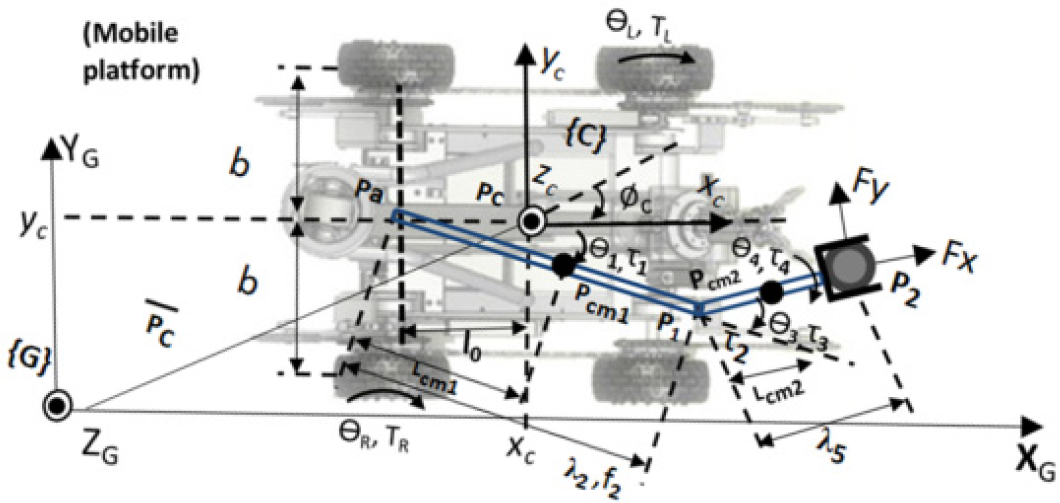
Remark 1, Like is shown in the figure below the locomotion of the traction system is formed by 2 drive wheels and 2 free wheels, the drive wheels are set in appositive way, which it allows the rotation of platform when vr = -v1, constituting the joint of torso for the case of handling task (Lewis, F. L., 1993).
Remark 2, Like is shown in the figure below the kinematic scheme for the case of handling task is governed by the equation q
WMM
= [q
WMM
q
WMM
]
T
= [φc θ1 d2 θ3 θ4]T, which omitted de translation in xc and yc Remark 3, Assumptions of Motion in a horizontal plane:
Punt of contact of wheels Wheels not deformables Rotate pure In the punt of contact v=0 Not slip Axis of steer ortogonales to the surface Wheels connected by a rigid body (chassis)

Kinematic Schematic for coupled system
The platform has two driving wheels and two passive supporting wheels. The two driving wheels are independently driven by the dc motors. The following notation will be used in the derivation of the constraint equations and dynamic equation (Yamamoto Y. & Yun X., 1994).

Kinematic Schematic for coupled system
Instantaneous center of rotation (ICR) or instantaneous center of curvature (ICC) is a cross point of all axes of the wheels (Jackey, A., 2002), with mobility degree 2 and degree of steereability 0.

Three variables (xc, yc, φc) describe the position and orientation of the platform. Two variables specify the angular positions for the driving wheels (Choset, H., 2005). Adding non-holonomic constraints Is that the platform must move in the direction of the axis of symmetry (holonomic).

Are the rolling constraints, not slip (non-holonomic).


The Mobile platform's equation of motion is described by:
M(q) N × N inertia matrix E(q) N × r input transformation matrix τ r-dimensional input vector
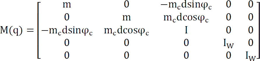
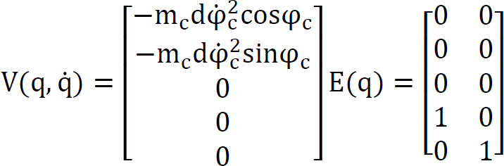
The system is subjected to three nonholonomic constraints of:

By taking the independent joint velocities 
This is valid for the case when the wheels are not slipping or skidding (Bayle B., Fourquet J.Y. & Renaud M., 2003). We define a look-ahead point Pa with Cartesian coordinates:

Kinematic Schematic for coupled system
The corresponding Jacobian that relates independent joint velocities to velocity of the look-ahead point is:


The rest of the parameters are listed in Table 2. The full set of extended generalized coordinates in this case, including the manipulator configuration variables, are 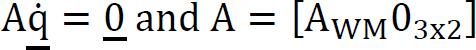
Modeling and simulation nomenclature

Denavit-Hartenberg kinematic parameters

Taking the independent velocities 
We consider the task-space to be the Cartesian coordinates of the end-effector
Finally, assume that the constrained dynamics of the MU-NH-WMM is written as:

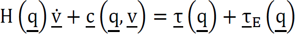
Where H = STHCS is the inertia, 
Where 
Where the first two terms are the joint-space acceleration required performing the task, and the last two terms represent the consistent joint-space acceleration due to the internal motion. The relationship between the task forces 
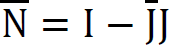
Where NT = I - JTJ#T projects the arbitrary (internal) joint torques 
Such an inertia-matrix weighted pseudoinverse has geometric significance since it endows the final task space with a kinetic energy metric defined on the tangent space of a selected manipulator (Bullo, F. & Lewis, A. D., 2004).

In (23), Γ1 filters the overall dynamics using JTJ#T to allow only the task-space dynamics to pass through. Likewise, Γ2 uses NT to retain the null-space component of the combined dynamics. Γ3Includes all the cross-coupling dynamic terms. Thus, taking 
Where 
Where 
We note that due to the explicit performance of nonlinear feedback linearization, the two subspace dynamics correspond to those of equivalent linear systems. Hence for the task-space, we select an impedance controller (Tang, C. P.; Bhatt, R. M.; Abou-Samah, M.; & Krovi, V., 2006):

Where the superscript d indicates the desired quantities; 
Where to 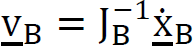
This can be extended to factor in a closed-loop Cartesian error dynamic for the look-ahead point as:

Where
In this section, a mechatronic unit with ability to move in a vertical plane which is mounted on a 4-wheeled vehicle is considered. Because of the especial task of the mobile manipulator, the path of mechatronic unit and the desired task of the end-effector are predefined. Thus there are some limited configurations of manipulator while moving along its desired path. These arrangements of manipulator do not satisfy the zero. The schematic picture of redundant manipulator with attached coordinates to its links is shown in Figure 7, the free body diagram of the mechatronic unit coupled is also shown in this figure.

Schematic diagram of mechatronic unit.
The forces and torques equations in x-y plane are as follows:


Assuming that the vehicle of mobile manipulator is symmetric with respect to x-y plane, it is clear that the forces Fy1 and Fy3 are equal and also Fy2 is equal to Fy4 Considering the unit at the steady state conditions, where velocities at different directions are constant, the kinematic equations may be found as follows:


The velocities and acceleration equations of the end-effector can also be determined by differentiating from equations with respect to time (Fruchard, M.; Morin, P. & Samson, C., 2006). Therefore, for solving the inverse kinematics of the system, two equations for the position of the end-effector in the x-y plane, two equations for velocity of the end-effector are employed. These are further to the two equations for the acceleration of the end-effector which are zero in this work. The 9 unknown variables are; θ1, Λ2, θ3 for angular positions,
For optimal stability of the mobile manipulator, the summation of tires upward forces Fy1, Fy3 should be set equal to the summation of forces Fy2 and Fy4. This leads us to define a performance index to be at its minimum value during the motion of mobile manipulator. This performance index can be set equal to the torque exerted on the first joint of manipulator attached to theunit. This equation is calculated by Lagrangian method and its accuracy is checked with the Newton- Euler iteration technique (Velinsky S. A. & Gardner, J. F., 2000). The torque acting on the first joint in the case of shooting to disposal the explosive device attached to the unit is as follow:

The Performance index of WMM when v = 1(m/s), b = 0.5(m), α = 0.5(rad). The design criterion was to control the mobile platform so that the manipulator is maintained at a configuration which maximizes the manipulability measure. We could use the desired path yd to feed back the error (Zuñiga, L.A.; Pedraza, J.C.; Gorrostieta E. & Ramos J.M., 2009)e = yd − y.


Demostration of rotation of mobile base about itself

Tracking trayectory in approaching

Tracking trayectory in approaching
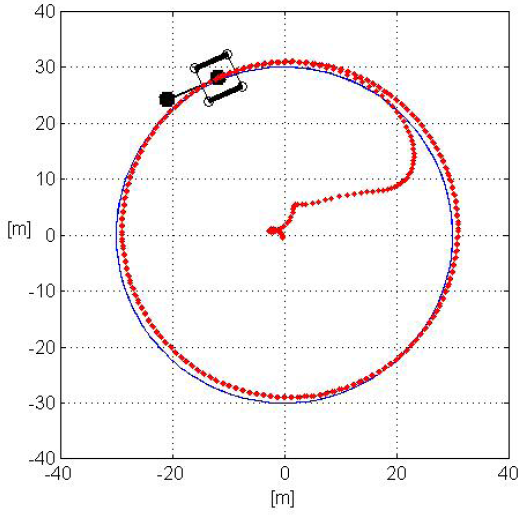
Tracking trayectory in approaching

Displacement of mobile base
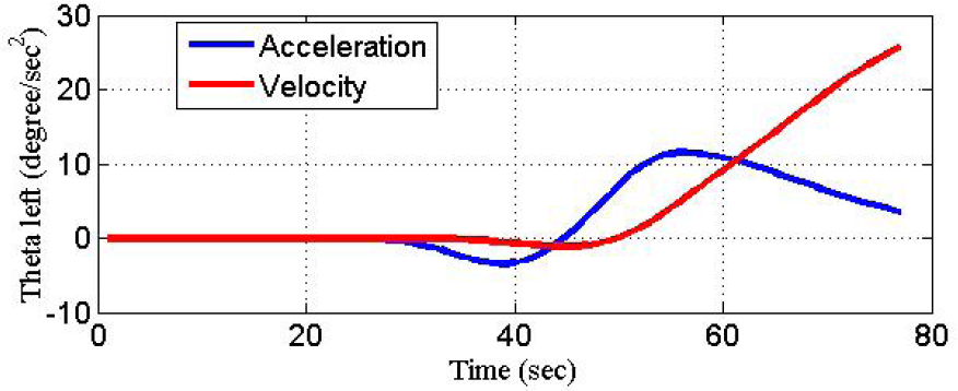
Velocity and acceleration of left wheel

Displacement of left wheel
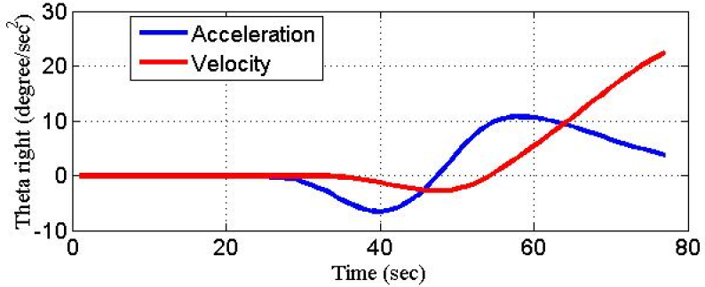
Velocity and acceleration of right wheel
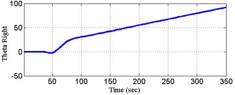
Displacement of right wheel.
In the next figure is presented the workspace of MU-WMM (Zuñiga, L.A., 2009).
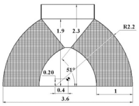
Workspace of mechatronic unit
The validation of mechanic structure is done by CAE software applying the analysis for element finite (fem) (Zuñiga, L.A., 2009), manufacturing the parts by aluminum 6061-T6, to load of 10 kg.
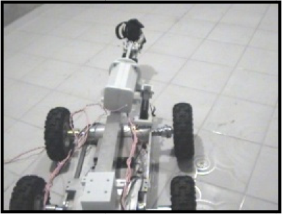
Prototype in test of trajectory tracking

Final technical specifications
Was satisfactory the methodology proposed of modeling and simulation which the Virtual rapid prototyping emulate the behavior of the robot validating the load and the mechanic system. In addition, the simulations displayed using a solid model, in such way that is possible observe the simulated motion system response. Dynamics and simulation environments were easily changed in either the simulation and in the control algorithm for the handling task, hence the proposed methodology gives the big picture of whole system, makes it easy understand the function of MU-NH-WMM. The stability of mechanical system is attached to symmetry of geometry and of loads. As future work, is considering the behavioral analysis in the approaching and transportation tasks considering the dynamic of load as well as the controller design for the coupled system and the methodology including the mechatronic design and the interaction with the mechanical, electronically and control systems.
Footnotes
8. Acknowledgement
The authors would like to thank the scientists, technicians and machinists of parts and whose devotion made this project possible. Special thanks are also due for CONACYT, CIDESI and SEDENA for providing financial assistance to one of the authors and funding the project.