
Abstract
In this paper, robust force/motion control strategies are presented for mobile manipulators under both holonomic and nonholonomic constraints in the presence of uncertainties and disturbances. The proposed control strategies guarantee that the system motion converges to the desired manifold with prescribed performance, and constraint force control is developed using the passivity of hybrid joint rather than force feedback control. Experiment results validate that not only the states of the system asymptotically converge to the desired trajectory, but also the constraint force asymptotically converges to the desired force.
1. Introduction
Mobile manipulators refer to robotic manipulators mounted on mobile platforms. Such systems combine the advantages of mobile platforms and robotic arms and reduce their drawbacks. For instance, the mobile platform extends the arm workspace, whereas the arm offers much operational functionality. Applications for such systems could be found in mining, construction, forestry, planetary exploration, and military.
Mobile manipulators possess complex and strongly coupled dynamics of mobile platforms and manipulators. A control approach by nonlinear feedback linearizaion was presented for the mobile platform so that the manipulator is always positioned at the preferred configurations measured by its manipulability (Yamamoto & Yun, 1994). In (Yamamoto & Yun, 1996), the effect of the dynamic interaction on the tracking performance of a mobile manipulator was studied, and nonlinear feedback control for the mobile manipulator was developed to compensate the dynamic interaction. In (Khatib,1999), a basic framework for the coordination and control of vehicle-arm systems was presented, which consists of two basic task-oriented control: end-effector task control and platform self posture control. The standard definition of manipulability was generalized to the case of mobile manipulators and the optimization of criteria inherited from manipulability considerations were given to generate the controls of the system when its end-effector motion was imposed (Bayle, Fourquet & Renaud, 2003).
The above literature concerning with control of the mobile manipulator has been limited to the systems whose dynamics are completely known. However, control of the entire state of the system with uncertainty is essential for practical applications, where not only the motion but also the force of the end-effector of the manipulator should be considered. Therefore, the state and the constraint force are required to asymptotically converge to the desired trajectory and constraint force, respectively, in the presence of uncertainty.
Adaptive Neural Network (NN) based controls for the arm and the base had been proposed for the joint-space position control of a mobile manipulator (Lin & Goldenberg, 2001), each NN control output comprise a linear control term and a compensation term for parameter uncertainty and disturbances. Adaptive control was proposed for trajectory/force control of mobile manipulators subjected to holonomic and nonholonomic constraints with unknown inertia parameters (Dong, 2002), which ensures the state of the system to asymptotically converge to the desired trajectory and force. In (Tan; Xi & Wang, 2003), a unified model for mobile manipulator was derived and nonlinear feedback was applied to linearize and decouple the model, and decoupled force/position control of the end-effector along the same direction for mobile manipulators was proposed and applied to nonholonomic cart pushing. This paper addresses the problem of stabilization of force/motion control for a class of mobile manipulator systems with both holonomic and nonholonomic constraints in the parameter uncertainties and external disturbances (Li; Gu; Ming; Xu & Shimojo, 2006). The main contributions of this paper are listed as follows:
Decoupling robust motion/force control strategies are presented for mobile manipulator with both holonomic and nonholonomic constraints in the parameter uncertainties and external disturbances;
Nonregressor based control design is developed in a unified manner without imposing any restriction on the system dynamics; and
Effective force control is investigated using the passivity of hybrid joint, which removes the need for the force sensor and eliminates the time-delay, noise and disturbance from the sensors.
The simulation and experiment results validate the system motion converges to the desired manifold with prescribed performance and with the bounded constraint force using the proposed control strategies.
The rest of the paper is organized as follows. The system description of mobile manipulator subject to nonholonomic constraints and holonomic are briefly described in Section 2. Problem statement for the system control is given in Section 3. The main results of robust adaptive control design are presented in Section 4. Simulation studies are presented by comparison between the proposed robust control with non-robust control in Section 5, and system setup and experiment results are provided in Section 6. Concluding remarks are given in Section 7.
2. System Description
Consider an n DOF mobile manipulator with a nonholonomic mobile base as shown in Fig.1. The constrained mechanical system can be described as
Space curve of trajectory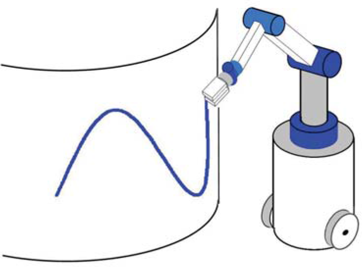

where q = [q1, …, q n ] T ∈ R n denote the generalized coordinates; M(q) ∈ Rnxn is the symmetric bounded positive definite inertia matrix; C(q̇, q)q̇ ∈ R n denotes the Centripetal and Coriolis torques; G(q) ∈ R n is the gravitational torque vector; d(t) denotes the external disturbances; τ ∈ R p are the control inputs; B(q) ∈ Rnxp is a full rank input transformation matrix and is assumed to be known because it is a function of fixed geometry of the system; f = J T λ ∈ R n denotes the vector of constraint forces; J is Jacobian matrix; and λ = [λ n T , λ h T ] are Lagarange multipliers corresponding to the nonholonomic and holonomic constraints. The generalized coordinates may be separated into two sets q = [q v ,q a ] T , where q v ∈ R v describes the generalized coordinates for the mobile platform; q a ∈ R m is the coordinates of the manipulator, and n = v + m.
The mobile platform is subjected to nonholonomic constraints, the l non-integrable and independent velocity constraints can be expressed as

where A = [A1 T (q v ), …, A l T (q v )] T : R v → Rlxv is the kinematic constraint matrix which is assumed to have full rank l. In the paper, the mobile base is assumed to be completely nonholonomic and exactly known. The effect of the constraints can be viewed as restricting the dynamics on the manifold Ω n as Ω n = {(q v ,q̇ v )| A(q v )q̇ v =0}. The generalized constraint forces for the nonholonomic constraints can be given by f v = A T (q)λ n , where λ n ∈ R l is known as force on the contact point between the rigid body and environmental surfaces.
Assume that the annihilator of the co-distribution spanned by the covector fields A1(q
v
), …, A
l
(q
v
) is an (v − l)-dimensional smooth nonsingular distribution Δ on R
v
. This distribution A is spanned by a set of (v − l) smooth and linearly independent vector fields H1(q
v
),…, Hv−l(q
v
), i.e., Δ = span{H1(q
v
), …, Hv−l(q
v
)}. Thus, H
T
(q
v
)A
T
(q
v
) = 0 with H(q
v
) = [H1(q
v
), …, Hv−l(q
v
)] ∈ Rvx(v−l). Note that H
T
H is of full rank. Constraints (2) implies the existence of vector
Considering the nonholonomic constraints (2) and its derivative, the dynamics of a mobile manipulator can be expressed as

Assume that the system (3) is subjected to k independent holonomic constraints, which can be written as
where h(q) is full rank, then J(q) = ∂h/∂q. The holonomic constraints could be further written as:

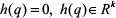
The holonomic constraint force f h can be converted to the joint space as f h = J T λ. Hence, the holonomic constraint on the robot's end-effector can be viewed as restricting only the dynamics on the constraint manifold Ω h defined by Ω h = {(q, q̇)|h(q) = 0, J(q)q̇ = 0}.
Assume that the mobile manipulator is a series-chain multi-link manipulator with holonomic constraints (i.e. geometric constraints). The vector q
a
can be further rearranged and partitioned into q
a
= [q
a
1, q
a
2]
T
, q
a
1 ∈ Rm−k describes the constrained motion of the manipulator, q
a
2 ∈ R
k
denotes the remaining joint variable. Then,

From (McClamroch & Wang, 1988), it could be concluded q is the function of ζ = [η, q
a
1]
T
, that is, q = q(ζ), and we have

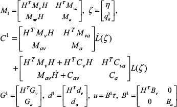
The dynamic model (3), when it restricted to the constraint surface, can be transformed into the reduced model:

where
Multiplying L
T
by both sides of (8), we can obtain

The force multipliers λ
h
can be obtained by (8)

where M L = L T M1L, C L = L T C1, G L = L T G1, Z = (J1(M1)−1J1T)−1J1(M 1 )−1.
3. Problem Statement
Since the system is subjected to the nonholonomic constraint (2) and holonomic constraint (4), the states q v , q a 1, q a 2 are not independent. By a proper partition of q a , q a 2 is uniquely determined by ζ = [η, q a 1] T . Therefore, it is not necessary to consider the control of q a 2.
Given a desired motion trajectory ζ
d
(t) = [η
d
q
a
1d]
T
and a desired constraint force f
d
(t), or, equivalently, a desired multiplier λ
h
(t), the trajectory and force tracking control is to determine a control law such that for any

4. Robust Control Design
Let
Consider the control input u as the form:

then, (9) and (10) can be changed to


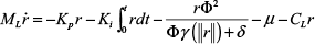
Consider the following control laws:


where C = [c1 c2 c3 c4 c5];
r converges to a small set containing the origin as t → ∞;
e q and ė q converge to 0 as t → ∞; and
eλ and τ are bounded for all t ≥ 0.
Proof
The closed-loop system dynamics can be rewritten as

Substituting (15) into (19), the closed-loop dynamic equation is obtained
where
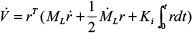
Consider the function,

then,
From Property 2.1, we have
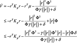
whenever
Integrating both sides of the above equation gives

Thus V is bounded, which implies that r ∈ L∞n−k.
From (23), we have ∫0
t
r
T
Krds ≤ V(0) − V(t) + a, which leads to r ∈ L2n−k. From
Therefore, all the signals on the right hand side of (20) are bounded and we can conclude that ṙ and therefore
Substituting the control (15) and (17) into the reduced order dynamic system model (14) yields

where L+ = (L
T
L)−1 L
T
. The proof is completed by noticing that since
5. Simulations
To verify the effectiveness of the proposed control algorithm, the model and parameters of mobile manipulator system in (Dong, 2002) are shown in Fig. 2. The mobile manipulator is subjected to the following constraints:
The Model of Mobile Manipulator

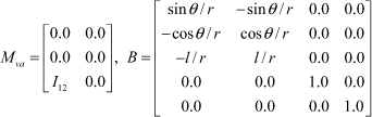
Using Lagrangian approach, we can obtain the standard form with q
v
= [x, y, θ]
T
, q
a
= [θ1, θ2]
T
, q = [q
v
, q
a
]
T
, and A
v
= [cosθ, sinθ, 0]
T
,


Let the desired trajectory q d = [x d , y d , θ d , θ1d, θ2d] T and the end-effector is subject to the geometric constraint: Φ = L1 + L2 sin(θ2) = 0, and y d =1.5sin(t), θ d = 1.0sin(t), θ1d = π/4(1-cos(t)), λ d = 10.0N.
The trajectory and force tracking control problem is to design control law τ such that (11) hold and all internal signals are bounded. In the simulation, we assume the parameter m p = m1 = m2 = 1.0, I w = I p = 1.0, I1 = I2 = 1.0, I = 0.5, d = l = r = 1.0, 2l1 = 1.0, l2 = 0.3, q(0) = [0, 4, 0.785, 0.1] T , q̇(0) = [0.0, 0.0, 0.0, 0.0] T By Theorem 4.1, the control gains are selected as K p = diag[1.0, 1.0, 1.0], Kζ = diag[2.0, 2.0, 2.0], K i = 0.0 and K f = 0.5. The adaptation gain in adaptation law (15) is chosen δ = 1/(1 + t)2 and C = [8.0, 8.0, 8.0, 8.0] T . The disturbance on the mobile base is set 0.1sin(t) and 0.1cos(t). The simulation result are shown in Figs. 3–6. The simulation results show that the trajectory and force tracking errors asymptotically tend to zero, which validate the effectiveness of the control law in Theorem 4.1.

The positions of the joints
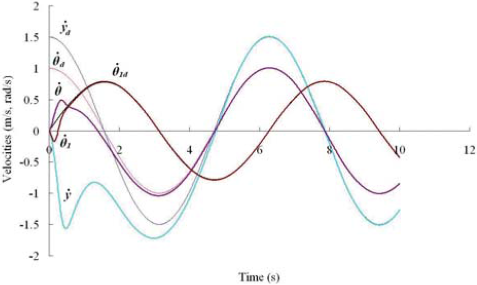
The velocities of the joints

The torques of the joints
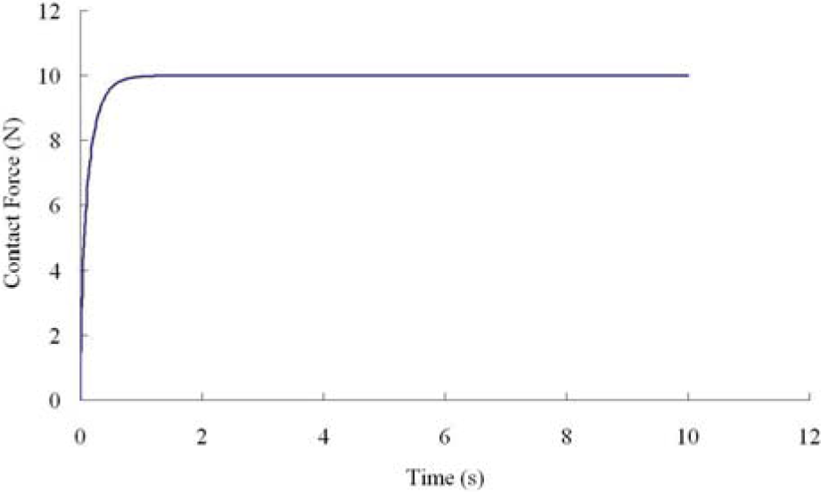
The constraint force
6. System Setup and Experiment
The hybrid joint presented in (Li; Ming; Xi; Gu & Shimojo, 2005) consists of an electromagnetic clutch between the motor and the output shaft as shown in Fig. 7. The hybrid joint has two exchangeable modes: passive and active mode. When the clutch is released, the joint is free and switched to the passive, and the free link is directly controlled by the coupling characteristics of the manipulator dynamics. When the clutch is on, the link is controlled with the motor. The nonholonomic mobile manipulator consists of a nonholonomic mobile platform and a 5-DOF arm, which has totally 5 revolute hybrid joints, as shown in Fig. 8. The control schematics is shown in Fig.9. The hybrid joints and brake unit are controlled by the DIO card and relay board.

The hybrid joint

The experimental mobile manipulator

The control schematics
Generally, a force sensor must be equipped with the end-effector to measure the contact force with the surface from (17). However, in our study, we make full use of the passivity of hybrid joint of mobile manipulator in which the deformation of link caused by contact force can be measured by the joint shaft encoder as shown in Fig. 7, if the hybrid joint is switched into the passive state. The holonomic constraint is a 3D curve on the cylinder which is vertical to the ground (X-Y plane) as shown in the Fig.1. We assume the joint 5 to be passive. All other joints are active and the corresponding joint angles are measured from the motor encoders. We can obtain the constraint force, as shown in Fig.10, simplified as:
Control Parameters


In the presence of frictional forces, the interacting force between the tool and the environment denoted here by f, is no longer orthogonal to the constraining surface and it is decomposed by f = f
x
+ f
y
, where f
y
= J
T
λ
h
and f
x
is the tangential friction force, ẋ is the tangential velocity of end-effector. The friction force can be computed by projecting the normal force along with the negative direction of velocity vector and the normal force is computed by β which is the absolute angle in the global coordinates; l is the length of tool; l5 is the length of link 5; lg5 is the length from the mass center of link 5 to the joint 5; m5 is the mass of the link 5. The relation of the normal force, β and the length of tool is shown in Fig. 11, where the ranges of length of tool and β are (40, 115) mm and (5, 80) deg, respectively. If q2
d
, q3
d
and β
d
is given, since q
5
is passive, it can be seen (25) can be easily satified. If the tool's length is given, from (25) and Fig. 11, the normal force is only a function of β, if β → β
d
, then f
y
→ f
y
d
and λ
h
→ λ
h
d
, so we design,
The relation of normal force, β and tool's length

As for the friction force, we could consider it among μ in (20).
We implement the above control method to trajectory and force control, for simplicity, we consider the holonomic constraint is 3D curve
Since the system is very complex, it is difficult to obtain the exact model of system, we roughly estimate the mass parameter of the 5 DOF manipulator as m1= 20kg, m2 = 15kg, m3 = 8kg, m4 = 5kg, m5 = 3kg, m b = 30kg, and the realtive exact parameters l1 = 10mm, l2 = 350mm, l3 = 500mm, l4 = 250mm, l5 = 250mm, q̇ i max = 10deg/s, q̈imax = 3deg/s2, (i = 1, …, 6), vbasemax = 2m/s; the diameter of the mobile base is 600mm, g = 9.8kg/m2, the length of tool is give as 50mm, K f = 0.1, K p = diag[80], K i = 0, K t = diag[60], δ = 1/(1 + t2), the desired force is 4N, we can obtain the desired angle β = 20 deg.
The control results are shown in Fig. 12 and Fig. 13, they are the trajectory tracking error and constraint force tracking error, respectively, under different the desired velocity of mobile base(20mm/s-40mm/s). It can be seen that the motion error converges to zero and the force error remains bounded simultaneously. Althoug both tracking error is fluctuated a little as the velocity of the mobile base increased, the error result is within the enough accuracy (5%).

Trajectory Tracking

Force Tracking, the desired β=20 deg
7. Conclusion
Decoupling robust motion/force control strategies have benn presented for mobile manipulator with both holonomic and nonholonomic constraints in the parameter uncertainties and external disturbances. Nonregressor based control design has been developed in a unified manner without imposing any restriction on the system dynamics; and effective force control is investigated using the passivity of hybrid joint, which removes the need for the force sensor and eliminates the time-delay, noise and disturbance from the sensors. Simulation studies and experiments have verified the effectiveness of the proposed controller.
Footnotes
8. Acknowledgement
This work is partly supported by the Natural Science Foundation of China under grant 60475032 and the Shu Guang Project of Shanghai Municipal Education Commission and Shanghai Education Development Foundation.